Linux Note (Updateing)
- zsh --
记得安装 oh-my-zsh, Powerlevel10k - bash --
- tree --
- duf -- df 替代
-
图形基础框架:
xorg -- 安装过程中会要求安装 xorg 扩展工具,如果空间足够,默认就行,关于 man 的安装包安装
man-db或者manpage都可以 xf86-video-intel -- 可参考 arch xorg 官方文档 安装和是的驱动程序 xorg-xinit -- startx 脚本 - awesome -- 超轻量级桌面管理器
-
输入工具:
fcitx -
fcitx-configtool -
fcitx-googlepinyin - fcitx 的 google 拼音实现
ssfconv -- fxitx 搜狗拼音
-
网络管理:
networkmanager -- 是一个为系统提供检测和配置功能以便自动连接到网络的程序
network-manager-applet -- 系统托盘程序
更多和网络管理相关的工具参考: archlinux netmanager 介绍 -
系统电源管理:
xfce4-power-manager --
更多关于电源管理工具参考: arch 关于 电源管理介绍 -
pulseaudio 工具:
pulseaudio --
pulseaudio-alsa --
pulseaudio-bluetooth -- 如果你要连接蓝牙就一定要安装这个包
pa-applet --PulseAudio 的系统托盘小程序,带音量条。
更多关于 pulseaudio 工具的介绍参考: arch 关于 电源管理介绍 -
蓝牙相关工具:
bluez --
bluez-utils --
blueberry -- mint 的图形管理工具 - konsole -- 超好用的终端管理工具
-
系统管理工具
baobab -- A graphical directory tree analyzer
duf -- -
图像查看工具:
eog --
nomacs -- - calibre -- 查阅电子书的工具
- curl -- 勿需多言
- wget -- 勿需多言
- axel -- 命令行的下载工具,支持多线程断点续传,非常 awsome
- deluge -- 下载工具
- aria2 -- 一个下载工具,可以下载 BT 或者磁力链接,
可以使用这个库更新根节点 trackerlist,
另外还可以使用 node.js 的一个 web 服务充当前端: webui-aria2
下面是一个 bringup 的脚本:
#!/bin/bash echo '... update bt trackerlist' cd ~/CC/software/trackerslist git pull; tvTrackerList='' tvTrackerArr=$(cat trackers_best_ip.txt | grep -E "\S+") for track in ${tvTrackerArr} do # echo ${tvTrackerList} if [ "${tvTrackerList}" = "" ]; then tvTrackerList=${track} else tvTrackerList=${tvTrackerList},${track} fi done tvTrackerList="bt-tracker=${tvTrackerList}" sed -i "s#bt-tracker=.*#${tvTrackerList}#g" ~/config/aria2/aria2.conf echo "${tvTrackerList}" aria2c --conf-path=$HOME/config/aria2/aria2.conf >> /tmp/ariac.log & sleep 1; cd ~/CC/software/webui-aria2; node node-server.js &> /tmp/webui.log & - autojump -- A faster way to navigate your filesystem from the command line
- 浏览器:
chromium -- chromium 可以直接安装
chrome -- 这个需要到 chrome 的官网下载 deb 或者 rpm 包解压手动安装
- ntfs-3g --
- duf --
- Fuck GFW: *** --
- C/C++ 相关常规编译工具
gcc --
gdb --
gcc-fortran --
clang --
gcc --
binutils -- 提供 addr2line, ar, as, c++filt, dwp, elfedit, gold, gprof, gprofng, ld, nm, objcopy, objdump, ranlib, readelf, size, strings, strip 等工具
make --
cmake --
autoconf --
automake --
ccache -- C 编译加速工具 -
node.js 相关:
nvm -- 安装与切换 node.js 不同版本的工具
-
java 相关:
jdk --
jdk-openjdk -- 还有一系列 jdk8-openjdk / jdk10-openjdk / jdk11-openjdk ... 如果安装了多个环境可使用archlinux-java进行切换
java-environment-common --
java-runtime-common --
gradle -- - go --
- python --
- cython -- 包含 C 数据类型的 python
- julia --
- electron --
-
lua52 lua53 -- 超轻量级,超性能编程解释器
luarocks -- lua 模块的发布与管理工具 - js --
-
数据库相关:
sqlite --
mongodb --
db -- The Berkeley DB embedded database system -
office 工具:
wps-office -- - bonnie++ -- 给硬盘做 benchmark 的工具
- minicom -- 串口调试工具
- evtest -- 测试 Linux 事件工具
-
网络调试工具:
wpa_supplicant --
nethogs --
networkmanager / network-manager-apple / networkmanager-qt -
压缩工具:
tar --
cpio --
gzip --
zip -- -
命令行播放工具:
alsaplayer -- alsa 官方提供的播放工具
mplayer --
ffmpeg -- - arduino -- arduino 官方 IDE
- arm 相关交叉编译工具: arm-none-eabi-binutils, arm-none-eabi-gcc, arm-none-eabi-gdb, arm-none-eabi-newlib
- audacity -- 音频编辑分析工具,可用于分析 PCM, MP3, ACC ... 功能非常强大,对标 audition
- cura -- 3D 打印切片工具
-
图像处理
openjpeg --
opencv -- - minicon -- 串口调试工具
- vim -- ctags -- 不要忘了安装这个强力工具
- android-studio, android-sdk -- Android 开发工具
- code ( vs code ) --
- octave -- 开源的 matlab
- codeblocks --
- meld -- 对标 beyound
- netease-cloud-music -- 网易云
- elisa
- strawberry, github 仓库地址
- deepin-music -- deepin 自带的音乐播放器
- ffmpeg --
-
矩阵运算库:
blas -- Basic Linear Algebra Subprograms
blas-openblas -- An optimized BLAS library based on GotoBLAS2 1.13 BSD (Provides BLAS/CBLAS/LAPACK/LAPACKE system-wide)
以上还有 64 位版本 blas64 blas64-openblas - bluez -- 蓝牙协议栈,提供丰富的蓝牙接口供应用层调用
以下是我 pip 的配置:
❯ cat ~/.pip/pip.conf
[global]
    index-url = https://pypi.tuna.tsinghua.edu.cn/simple/
以下爱是我常用的一些安装包:
- request --
pip install --break-system-packages request - numpy --
pip install --break-system-packages numpy - panda --
pip install --break-system-packages panda - matplotlib --
pip install --break-system-packages matplotlib - nltk --
pip install --break-system-packages nltk - seaborn --
pip install --break-system-packages seaborn - scipy --
pip install --break-system-packages scipy - cv2 --
pip install --break-system-packages cv2 - sphinx --
pip install --break-system-packages sphinx - pyserial --
pip install --break-system-packages pyserial - pyautogui --
pip install --break-system-packages pyautogui
- 安装
参考本小节参考文档中的安装指南
首先是 UEFI 还是 BIOS 的问题,因为这个可能会设计到后面分区的问题 BIOS+GPT+GRUB 大约 1M 就够了,通常我们会给 boot 分大约 200M, 但是如果是 UEFI 推荐引导就超过 256M ,因此最好先看一看自己系统是不是只支持 UEFI ,像苹果那种,我之前就踩了这个坑。
有两条建议,还有就是在进行安装的时候建议在安装阶段就把必要的像网络管理工具和编辑工具安装好,比如说我就非常不适应 vi 因此还是先把 vim 装上吧。 另外就是可以升级了之后再退出安装。这样会避免一些不必要的麻烦。 - 下载/升级源
搜索可用源 https://archlinux.org/mirrorlist/
官方维护的源状态 https://archlinux.org/mirrors/status/ - 安装问题1
描述:如果你在安装或者升级的时候遇到类似这种错误,error: PKGNAME: signature from "USERNAME <EMAIL_NAME>" is unknown trust
如:error: libspeech: signature from "Alexander Epaneshikov <email@alex19ep.me>" is unknown trust
八成是因为你本地密钥库破坏,或者很久没有更新导致丢失某些密钥导致,网上有推荐的一种方法是设置不对包进行任何签名校验,很显然这样有非常大的安全风险。
如果你不愿意一个一个慢慢的修复,一个方法是执行下面步骤中的 step4, 但是偶尔也有失败的情况,因此一步到位的方法是将下列 step1 - step4 都操作一遍。
step1: 删除本地缓存签名:sudo rm -rf /etc/pacman.d/gnupg/*
step2: 重新初始化密钥库:sudo pacman-key --init
step3: 重新添加密钥:sudo pacman-key --populate archlinux
step4: 再次刷新一遍:sudo pacman-key --refresh-keys, 这一步骤可能会花费你几分钟到几十分钟的时间 - 如何登陆 Windows 远程管理界面
安装 freerdpsudo pacman -S freerdp( ubuntu 安装sudo apt install freerdp2-x11)
运行以下命令xfreerdp /v:1.2.3.4 /u:Administrator /p:PASSWORD - 安装 deepin-screenshot-copy
因为最新的 deepin-screen-recorder 出现了一些不兼容的情况,请参考 https://wiki.archlinux.org/index.php/Screen_capture, 因此在这里我们需要安装 https://aur.archlinux.org/packages/deepin-screenshot-copy-patch/
在命令行执行以下脚本安装cd /tmp/; git clone https://aur.archlinux.org/deepin-screenshot-copy-patch.git; cd /tmp/deepin-screenshot-copy-patch; makepkg -si
- Getting and installing Arch(其中介绍了怎么制作安装介质)
- Arch Linux 安装指南[2016.01]
- 文件系统,以及支持文件系统所需要安装的包
- 迁移系统到新硬件中(Migrate installation to new hardware)
- 查找软件安装位置: dpkg -S
- 以及安装了那些软件: dpkg -L
- ubuntu 包管理
查看当前安装的包
dpkg -l,卸载软件时卸载之依赖包(如果此依赖包还被其他依赖,将不被卸载),请使用aptitude命令(其中remove是删除软件以及其依赖,purge,删除软件,以及其依赖,以及其配置文件),apt-get的autoremove参数也可以用来卸载当前指定包以及其依赖。但真心不好用,参考一下aptitude , pacman就知道。不过 ubuntu 上的包资源很全面。
- 升级更新
同 ubuntuapt-get update; apt-get upgrade - Kali 源
在 /etc/apt/source-list 中添加以下两行deb http://mirrors.ustc.edu.cn/kali kali-rolling main non-free contrib deb-src http://mirrors.ustc.edu.cn/kali kali-rolling main non-free contrib - virtualbox 全屏问题
执行以下代码修复apt-get update; apt-get install -y virtualbox-guest-x11; reboot, 参考 此处 - 分区规划
如果跟分区与 home 分区分开,建议至少保证根分区大于 11G 否则后续更新会比较吃力,我自己的是 20G, 安装在 virtualbox 上,应付日常开发足矣。
- 清华源( Debian 10( buster ) )
# 编辑 `/etc/apt/sources.list` 文件,删除原文件所有内容,用以下内容取代:
deb http://mirrors.tuna.tsinghua.edu.cn/raspbian/raspbian/ buster main non-free contrib rpi
deb-src http://mirrors.tuna.tsinghua.edu.cn/raspbian/raspbian/ buster main non-free contrib rpi

# 编辑 `/etc/apt/sources.list.d/raspi.list` 文件,删除原文件所有内容,用以下内容取代:
deb http://mirrors.tuna.tsinghua.edu.cn/raspberrypi/ buster main ui
- 使能 Camera
在终端运行下面这条命令:sudo raspi-config,然后顺着下面的步骤设置就可以了: Select :5 Interfacing Options Configure connections to peripherals--> Select :P1 Camera Enable/Disable connection to the Raspberry Pi Camera--> Select yes -->sudo reboot
检查是否安装成功执行以下命令:raspistill -o image.jpg, 该命令会在当前目录保存一个从摄像头撷取的一张图片,并保存到 image.jpg 中。 - 安装了 Camera 之后 无法发现 /dev/video 节点
如果你按照上面的步骤打开了树梅派的 Camera 功能,那么你可能在 /dev/目录下找不到 video[x] 节点。我查到的原因是树莓派中的camera module是放在/boot/目录下以固件的形式加载的,不是一个标准的v4l2的摄像头ko驱动。所以加载起来之后会找不到/dev/video[x] 的设备节点,这是因为这个驱动是在底层的,v4l2这个驱动框架还没有加载,所以要在/etc/modules-load.d/modules.conf里面添加一行bcm2835-v4l2,然后重启,就可以了。(这句话意思是在系统启动之后会加载这个文件中模块名,加载模块会在/lib/modules中。)# sudo vim /etc/modules-load.d/modules.conf # 在文尾添加下面这行 bcm2835-v4l2 # find /lib/modules/ -name "*bcm2835-v4l2*" /lib/modules/4.9.35+/kernel/drivers/media/platform/bcm2835/bcm2835-v4l2.ko /lib/modules/4.9.35-v7+/kernel/drivers/media/platform/bcm2835/bcm2835-v4l2.ko - 对 exfat 支持
安装apt-get install exfat-fuse - 对 ntfs 支持
安装apt-get install ntfs-3g - raspberry pi 发射热点 参考: https://www.raspberrypi.org/documentation/configuration/wireless/access-point-routed.md
- 引脚图
Ref: https://pinout.xyz/
- GPIO 电器特性
Ref: https://www.tomshardware.com/reviews/raspberry-pi-gpio-pinout,6122.html
The best thing about any Raspberry Pi, including the new Raspberry Pi 4, is that you can use it to build all kinds of awesome contraptions, from robots to retro gaming consoles and fart detectors. Most of the sensors, motors, lights and other peripherals that make these projects possible connect to the Pi's set of GPIO (General Purpose Input Output) pins. These pins offer a direct connection to the System on Chip (SoC) at the heart of the Pi, enabling the Pi to communicate with external components. Every Pi model since the Raspberry Pi B+ has had 40 GPIO pins, though on the Pi Zero and Zero W, you have 40 holes that you can solder pins or wires into.
This guide has been updated to reflect the new capabilities of the Raspberry Pi 4, which still comes with 40 GPIO pins, but has a few extra I2C, SPI and UART connections available.
No matter what you're building, you need to know the Raspberry Pi GPIO pinout, the map and explanation of what each pin can do. While some pins provide electricity, others are grounds and still others connect to different kinds of interfaces, all of which we explain below.- General Purpose Input Output (GPIO) Pins
The GPIO is the most basic, yet accessible aspect of the Raspberry Pi. GPIO pins are digital which means they can have two states, off or on. They can have a direction to receive or send current (input, output respectively) and we can control the state and direction of the pins using programming languages such as Python, JavaScript, node-RED etc.
The operating voltage of the GPIO pins is 3.3v with a maximum current draw of 16mA. This means that we can safely power one or two LEDs (Light Emitting Diodes) from a single GPIO pin, via a resistor. But for anything requiring more current, a DC motor for example, we will need to use external components to ensure that we do not damage the GPIO.
Controlling a GPIO pin with Python is accomplished by first importing a library of pre-written code. The most common library is RPi.GPIO (https://pypi.org/project/RPi.GPIO/) and it has been used to create thousands of projects since the early days of the Raspberry Pi. In more recent times a new library called GPIO Zero (https://pypi.org/project/gpiozero/)has been introduced, offering an easier entry for those new to Python and basic electronics. Both of these libraries come pre-installed with the Raspbian operating system.
GPIO pins have multiple names; the first most obvious reference is their “physical” location on the GPIO. Starting at the top left of the GPIO, and by that we mean the pin nearest to where the micro SD card is inserted, we have physical pin 1 which provides 3v3 power. To the right of that pin is physical pin 2 which provides 5v power. The pin numbers then increase as we move down each column, with pin 1 going to pin 3, 5,7 etc until we reach pin 39. You will quickly see that each pin from 1 to 39 in this column follows an odd number sequence. And for the column starting with pin 2 it will go 4,6,8 etc until it reaches 40. Following an even number sequence. Physical pin numbering is the most basic way to locate a pin, but many of the tutorials written for the Raspberry Pi follow a different numbering sequence.
Broadcom (BCM) pin numbering (aka GPIO pin numbering) seems to be chaotic to the average user. With GPIO17, 22 and 27 following on from each other with little thought to logical numbering. The BCM pin mapping refers to the GPIO pins that have been directly connected to the System on a Chip (SoC) of the Raspberry Pi. In essence we have direct links to the brain of our Pi to connect sensors and components for use in our projects.
You will see the majority of Raspberry Pi tutorials using this reference and that is because it is the officially supported pin numbering scheme from the Raspberry Pi Foundation. So it is best practice to start using and learning the BCM pin numbering scheme as it will become second nature to you over time. Also note that BCM and GPIO pin numbering refer to the same scheme. So for example GPIO17 is the same as BCM17.
Certain GPIO pins also have alternate functions that allow them to interface with different kinds of devices that use the I2C, SPI or UART protocols. For example GPIO3 and GPIO 4 are also SDA and SCL I2C pins used to connect devices using the I2C protocol. To use these pins with these protocols we need to enable the interfaces using the Raspberry Pi Configuration application found in the Raspbian OS, Preferences menu. - I2C, SPI and UART: Which Do You Use?
We'll get into the specific differences between I2C, SPI and UART below, but if you're wondering which one you need to use to connect to given device, the short answer is to check the spec sheet. For example, one tiny LED screen might require SPI and another might use I2C (almost nothing uses UART). If you read the documentation that comes with a product (provided it has some), it will usually tell you which Pi pins to use.
For Raspberry Pi 4 users note that there are now many more I2C, SPI and UART pins available to you. These extra interfaces are activated using device tree overlays and can provide four extra SPI, I2C and UART connections. - I2C - Inter-Integrated Circuit
I2C is a low speed two wire serial protocol to connect devices using the I2C standard. Devices using the I2C standard have a master slave relationship. There can be more than one master, but each slave device requires a unique address, obtained by the manufacturer from NXP, formerly known as Philips Semiconductors. This means that we can talk to multiple devices on a single I2C connection as each device is unique and discoverable by the user and the computer using Linux commands such as i2cdetect.
As mentioned earlier I2C has two connections: SDA and SCL. They work by sending data to and from the SDA connection, with the speed controlled via the SCL pin. I2C is a quick and easy way to add many different components, such as LCD / OLED screens, temperature sensors and analog to digital converters for use with photoresistors etc to you project. While proving to be a little more tricky to understand than standard GPIO pins, the knowledge gained from learning I2C will serve you well as you will understand how to connect higher precision sensors for use in the field.
The Raspberry Pi has two I2C connections at GPIO 2 and 3 (SDA and SCL) are for I2C0 (master) and physical pins 27 and 28 are I2C pins that enable the Pi to talk to compatible HAT (Hardware Attached on Top) add on boards. - SPI - Serial Peripheral Interface
SPI is another protocol for connecting compatible devices to your Raspberry Pi. It is similar to I2C in that there is a master slave relationship between the Raspberry Pi and the devices connected to it.
Typically SPI is used to send data over short distances between microcontrollers and components such as shift registers, sensors and even an SD card. Data is synchronised using a clock (SCLK at GPIO11) from the master (our Pi) and the data is sent from the Pi to our SPI component using the MOSI (GPIO GPIO10) pin. MOSI stands for Master Out Slave In. If the component needs to reply to our Pi, then it will send data back using the MISO pin (GPIO9) which stands for Master In Slave Out. - UART - Universal Asynchronous Receiver / Transmitter
Commonly known as “Serial,” the UART pins (Transmit GPIO14, Receive GPIO15) provide a console / terminal login for headless setup, which means connecting to the Pi without a keyboard or pointing device. Normally, the easiest way to do a headless Raspberry Pi setup is simply to control the Pi over a network or direct USB connection (in the case of Pi Zero).
But, if there's no network connection, you can also control a headless Pi using a serial cable or USB to serial board from a computer running a terminal console. UART is exceptionally reliable and provides access to a Pi without the need for extra equipment. Just remember to enable the Serial Console in the Raspberry Pi Configuration application. Chances are that you won't want to do this, but the UART support is there if you need it. - Ground (gnd)
Ground is commonly referred to as GND, gnd or - but they all mean the same thing. GND is where all voltages can be measured from and it also completes an electrical circuit. It is our zero point and by connecting a component, such as an LED to a power source and ground the component becomes part of the circuit and current will flow through the LED and produce light.
When building circuits it is always wise to make your ground connections first before applying any power as it will prevent any issues with sensitive components. The Raspberry Pi has eight ground connections along the GPIO and each of these ground pins connects to one single ground connection. So the choice of which ground pin to use is determined by personal preference, or convenience when connecting components. - 5v
The 5v pins give direct access to the 5v supply coming from your mains adaptor, less power than used by the Raspberry Pi itself. A Pi can be powered directly from these pins, and it can also power other 5v devices. When using these pins directly, be careful and check your voltages before making a connection because they bypass any safety features, such as the voltage regulator and fuse which are there to protect your Pi. Bypass these with a higher voltage and you could render your Pi inoperable. - 3v3
The 3v pin is there to offer a stable 3.3v supply to power components and to test LEDs. In reality, it will be rare that you factor this pin into a build, but it does have a special use. When connecting an LED to the GPIO, we first need to make sure that the LED is wired up correctly and that it lights up. By connecting the long leg of the LED, the anode to the 3.3v pin via a resistor, and the shorter leg, the cathode to any of the Ground (gnd) pins we can check that our LED lights up and is working. This eliminates a hardware fault from the project and enables us to start building our project with confidence.
- General Purpose Input Output (GPIO) Pins
- [1]raspberry pi 应用程序仓库
- [2]树莓派raspbian系统下,如何开启摄像头/camera模块,并使用简单的命令
- [3]Camkit ( 使用C语言写成,包含了从:图像采集-->色彩转换-->H264编码-->RTP打包-->网络发送的全套接口 )
- 清华大学镜像站
- Raspberry Pi schema 下载
- Raspberry Pi 2/3/4 相关 datesheet layout 下载
- init system 历史
参考: https://blog.darknedgy.net/technology/2015/09/05/0/ - systemctl 一些基本的使用方法
service_name 代指服务的名称,其中 service 可是是具体的 demon (*.service),也可以是挂载点 (*.mount),套接口 (*.socket)-
systemctl start service_name--> 开启服务 -
systemctl stop service_name--> 关闭服务 -
systemctl restart service_name--> 重启服务 -
systemctl status service_name--> 查看服务的运行状态 -
systemctl enable service_name--> 将服务设置为启动 -
systemctl disable service_name--> 将服务取消开机启动 -
systemctl is-enabled( is-active, is-failed ) service_name--> 查看服务是否启用(是否为激活/运行状态,是否出现错误) -
systemctl show service_name--> 查看服务的配置详细信息 -
systemctl list-units--> 列出所有运行中单元 -
systemctl list-unit-files--> 列举所有(包括运行和未运行的)的单元 -
systemctl --failed--> 列举所有运行失败的单元 -
systemctl mask( unmask ) service_name--> 屏蔽(显示)服务 -
systemctl kill service_name--> 杀死服务 -
systemctl show -p CPUShares service_name--> 获取当前服务的 cpu 分配额 -
systemctl set-property service_name CPUShares=2000--> 将某个服务的 CPU 分配额设置成 2000 (一般默认是 1024) -
systemctl list-dependencies service_name--> 查看某个服务的依赖性 -
systemd-analyze critical-chain sevice_name--> 查看某个服务的关键链(如果不知道这是什么最好的办法就是动手测试,并 google ) -
systemd-cgls--> 按照等级,列举出控制组 -
systemd-cgtop--> 按CPU、内存、输入和输出列出控制组 -
systemctl rescue--> 进入系统救援模式 -
systemctl emergency--> 进入系统紧急模式 -
systemctl get-default--> 列举出当前的运行等级 -
systemctl isolate runlevel5.target--> 启动运行等级(5,图形模式)(PS:以此类推) -
systemctl set-default runlevel(x:3,5...).target--> 设置默认运行等级 -
systemctl reboot--> 重启 -
systemctl halt--> 停止 -
systemctl suspend--> 挂起 -
systemctl hibernate--> 休眠(PS:休眠和混合睡眠都要求系统拥有 swap 分区,而且大小与内存一样大) -
systemctl hybrid-sleep--> 混合睡眠
-
- 一些其他的资料 采访 Systemd 和 PulseAudio 创始人 Lennart systemd、upstart和system V SystemV和BSD的区别 V
下面介绍一些简单的方法,可以在特定情况下提升命令行的体验,尤其是在服务器多人协作场景下:
- 防止某些 samba 客户端终端开太多连接
使用以下方法限制用户连接数/etc/samba/smb.conf [share] comment = A Shared Directory path = /home/share valid users = share public = no writable = yes max connections = 3
- 限制 ssh 客户端开太多连接
可在文件/etc/security/limits.conf中添加类似如下限制:限制 User1 的并发为 10 User1 hard maxlogins> 5 例子限制所有用户并发为 5 * hard maxlogins> 5
- 提升 ssh 终端常规命令优先级,并限制某些特殊程序优先级
这里我们可能需要创建一个 systemd 的配置来帮助我们实现
首先我们实现一个监控脚本:nicemonitor.sh#!/bin/bash start_server(){ while true do # 将特殊线程,以及编译线程优先级调低 ps -aux | grep -E "vscode|netdata|make|cmake|build|javac" | awk '{print $2}' | while read P do renice +5 ${P}; done # 把 ssh 服务,以及用户常见长时应用优先级提高 ps -aux | grep -E "ssh" | awk '{print $2}' | while read P do renice -5 ${P}; done if [ -f /tmp/xxxxxxroottask ]; then rm /tmp/xxxxxxroottask && sync break; fi sleep 10 done } if [ "$1" = "start" ]; then start_server elif [ "$1" = "shutdown" ]; then touch /tmp/xxxxxxroottask fi
准备 systend 配置脚本:/etc/systemd/system/nicemonitor.service[Unit] Description=Ensure system stable runtime After=network.target [Service] User=root Group=root ExecStart=/root/bin/roottask.sh start ExecStop=/root/bin/roottask.sh shutdown Restart=always [Install] WantedBy=multi-user.target
以下是我司方便给用户开账户的脚本,实际使用中用户密码不应该这么简陋, 谨慎参考 :
#!/bin/bash

echo "Please input user name:"
read NAME

IS_EXIST=$(cat /etc/passwd | grep "${NAME}")

if [ "${IS_EXIST}" = "" ]; then
    echo "USERNAME: ${NAME}"
else
    echo "This man is exist, please select another one"
    echo "/etc/passwd -> ${IS_EXIST}"
    exit -1
fi

echo "Please input select user base home dir:"
echo "1. /home"
echo "2. /home2"
echo "3. /home3"
echo "4. /home4"
read HOME_DIR

case ${HOME_DIR} in
1|/home)
    HOME_DIR="/home"
    ;;
2|/home2)
    HOME_DIR="/home2"
    ;;
3|/home3)
    HOME_DIR="/home3"
    ;;
4|/home4)
    HOME_DIR="/home4"
    ;;
*)
    echo "Not this option"
    exit -1
    ;;
esac

SMB_CONFIG_CONTENT="[${NAME}]\n   comment = A Shared Directory\n   path = ${HOME_DIR}/${NAME}\n   valid users = ${NAME}\n   public = no\n   writable = yes\n   max connections = 10\n"

echo "---"
echo "USER --> ${NAME}"
echo "PASSWORD --> ${NAME}"
echo "HOME_DIR --> ${HOME_DIR}"
echo "SAMBA PASSWORD --> ${NAME}"

echo "--- SMB CONFIG"
echo -e "${SMB_CONFIG_CONTENT}"

useradd -d ${HOME_DIR}/${NAME} -m -p $(openssl passwd -1 ${NAME}) -s /bin/bash ${NAME}
smbpasswd -a ${NAME} -w ${NAME}
echo -e "${SMB_CONFIG_CONTENT}" >> /etc/samba/smb.conf
systemctl  restart smbd
解决 mount nfs 的时候出现 mount: wrong fs type, bad option, bad superblock on **** 的问题。
安装 nfs-utils 。
- 安装截屏工具
pacman -S scrot - 安装 xev 或者 evtest
pacman -S xorg-xev - 运行 xev 并且按 PrtSrc 你可能会收到如下信息, Print 则是该按键的名字
KeyPress event, serial 33, synthetic NO, window 0x2400001, root 0x1a1, subw 0x0, time 58322539, (691,875), root:(692,916), state 0x0, keycode 107 (keysym 0xff61, Print), same_screen YES, XLookupString gives 0 bytes: XmbLookupString gives 0 bytes: XFilterEvent returns: False - 如果你有上述报错信息,则在 awesome 的配置文件(
~/.config/awesome/rc.lua)中配置该功能即可:263 globalkeys = gears.table.join( ... 383 awful.key({ }, "Print", function (), 384 awful.util.spawn("scrot -e 'mv $f ~/Pictures/ 2> /dev/null'") end) ...
以下是我的 ~/.zshrc 的配置
export ZSH=/home/mojies/.oh-my-zsh
ZSH_THEME=mikeh
plugins=(git)
source $ZSH/oh-my-zsh.sh

alias vi='vim -O'
alias CP='rsync -avh --progress -v --links'
alias gitd='git difftool'
alias rm.origin='/usr/bin/rm'
alias rm='trash-put'
alias rm.ls='trash-list'
alias rm.rm='trash-rm'
alias rm.recovery='trash-restore'
alias rm.empty='trash-empty'
alias g++11='g++ -std=c++11'
alias g++14='g++ -std=c++14'
alias g++17='g++ -std=c++17'
alias g++20='g++ -std=c++2a'
alias top='glances'
alias AS='android-studio'
alias df='duf'

# awsome need pull up startx first
isrunning startx; if [ $? -ne 0 ]; then startx;  fi

export WORKON_HOME='~/.virtualenvs'
source /usr/bin/virtualenvwrapper.sh
一个在命令行自动补全命令的工具, 建议终端开 256 色
echo 1 > /proc/sys/vm/drop_caches 释放页缓存
echo 2 > /proc/sys/vm/drop_caches 释放 dentries 和 inode 缓存
echo 3 > /proc/sys/vm/drop_caches 释放所有缓存(以上三种)
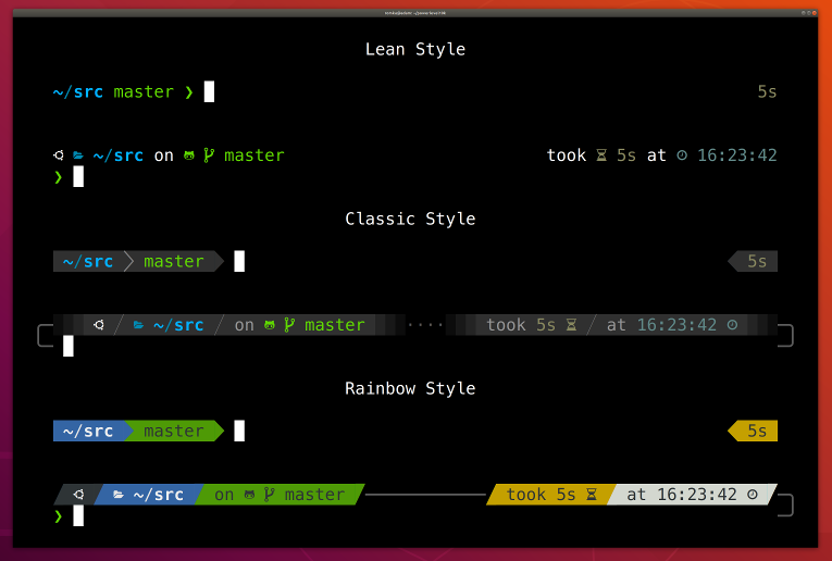
借用他们的原话是:
Powerlevel10k is a theme for Zsh. It emphasizes speed, flexibility and out-of-the-box experience.
给大家展示一下效果图:
- POSIX 标准
POSIX(Portable Operating System Interface for Computing Systems)是由IEEE 和ISO/IEC 开发的一簇标准。该标准是基于现有的UNIX 实践和经验,描述了操作系统的调用服务接口,用于保证编制的应用程序可以在源代码一级上在多种操作系统上移植运行。它是在1980 年早期一个UNIX 用户组(usr/group)的早期工作的基础上取得的。该UNIX 用户组原来试图将AT&T 的系统V 和Berkeley CSRG的BSD 系统的调用接口之间的区别重新调和集成,从而于1984 年产生了/usr/group 标准。1985 年,IEEE操作系统技术委员会标准小组委员会(TCOS-SS)开始在ANSI 的支持下责成IEEE 标准委员会制定有关程序源代码可移植性操作系统服务接口正式标准。到了1986 年4 月,IEEE 就制定出了试用标准。第一个正式标准是在1988 年9 月份批准的(IEEE 1003.1-1988),也既以后经常提到的POSIX.1 标准。
更加详细的资料请参考:这里 - Linux 内核知识点(摘抄自《性能之巅》)
操作系统层级系统调用多任务处理进程进程属性虚拟内存全局文件系统文件系统权限设备文件缓冲区高速缓存换页虚拟内存按需换页快文件系统(fast file system, FFS)TCL/IP 协议栈套接字VFSNFS页缓存统一页缓存slab 分配器DFSDTrace( atrace, eBPF )资源 fork - Linux 与性能有关知识点(摘抄自《性能之巅》)
CPU 调度级别I/O 调度级别TCP 拥塞OvercommitFutex巨型页OprofileRCUepoll模块 I/O 调度DebugFsCpusets自愿内核抢占inotifyblktreesplice延时审计IO 审计DynTicksSLUBCFScgroupslatencytopTracepointsperf透明巨型页UprobsKVM - 在分析一个应用的性能之前因先熟悉该应用的相关知识
功能,操作,CPU 模式,配置,指标,日志,版本,Bugs List,社区,书,专家 - 线程调度策略
- SCHED_OTHER 分时调度策略
- SCHED_FIFO 实时调度策略,先到先服务
- SCHED_RR 实时调度策略,时间片轮转
- OOM
各个进程的 oom_adj 调节路径/proc/${PID}/oom_score_adj, 数值越小,说明等级越重要,数值范围[-17, 15], 当值为 -17 的时候该进程将不会纳入 oom 的考量范围。
进程的 score 路径/proc/${PID}/oom_score
oom 的决策源码路径:linux/mm/oom_kill.c
因为 Linux 进程的创建机制,子进程会继承父进程的 adj 的值 - 写时拷贝( copy-on-write, COW )
当 fork 线程的时候,fork 中线程的数据结构为夫进程的引用,而当在执行过程中真正要修改某项参数的时候才会分配新的内存(创建新的副本) - 进程的生命周期
进程创建的时候为 idle,随后会被内核转移到 ready-to-run 运行队列中,只有 ready-to-run 的进程可以进入 on-proc 状态
正在运行的进程可能因为阻塞,或者主动睡眠进入 sleep 状态,等到资源就绪之后会重新进入 read-to-run 的状态
子进程调用 exit 之后会进入 zombie 状态
假设子进程结束时父进程仍存在,而父进程 fork() 之前既没设置 SIGCHLD 信号处理函数调用 waitpid()等待子进程结束,又没有显式忽略该信号,则子进程成为常驻 zombie 进程
zombie 进程即使是 root 身份 kill -9 也不能杀死。补救办法是杀死僵尸进程的父进程(僵尸进程的父进程必然存在),僵尸进程成为"孤儿进程",过继给 1 号进程 init ,init 始终会负责清理僵尸进程。 - 系统调用
通过man syscalls可以查看系统支持的系统调用,在用man ${func}可以查看用法,其次还可参考 《UNIX 环境高级编程》 或者内核源码 - 绑定一个进程到一个 CPU
如果是命令行,可以通过 taskset 实现,如taskset -pc 2-3 1234将进程号为 1234 的 进程绑定到 2-3 号 CPU 上
如果是在代码里面,可以通过 sched_setaffinity 系统调用接口实现,头文件为sched.h, 使用extern long sched_getaffinity(pid_t pid, struct cpumask *mask);来获取进程被固定到那些 CPU 上, 使用extern long sched_setaffinity(pid_t pid, const struct cpumask *new_mask);将进程固定到某些 CPU 上, 其中 pid 为进程号,如果你设置为 0, 则设置默认为当前进程, cpumask 被定义为typedef struct cpumask { DECLARE_BITMAP(bits, NR_CPUS); } cpumask_t;, 而 DECLARE_BITMAP 又被定义为#define DECLARE_BITMAP(name,bits) unsigned long name[BITS_TO_LONGS(bits)], 不同内核版本之间有不同的区别,具体请参考include/linux/sched.h。
如果想要绑定线程到 CPU 上,则使用pthread.h中的pthread_setaffinity_np方法,使用方式和进程的类似, 请直接查询pthread.h头文件。
请注意如果你把一个进程固定到了一个 CPU 上,其衍生的 - 创建独占 CPU 组
这是内核文档scheduler/sched-deadline.txt给出的一个例子,也可以参考: https://man7.org/linux/man-pages/man7/cpuset.7.htmlmkdir /dev/cpuset mount -t cgroup -o cpuset cpuset /dev/cpuset cd /dev/cpuset # 创建一个名为 cpu0 的 cpuset mkdir cpu0 # 指定该 cpuset 中包含哪些 cpu, 也可以 1-3 的方式指定该 cpuset 包含 [1,2,3], # 具体的格式也在 scheduler/sched-deadline.txt 文档中 echo 0 > cpu0/cpuset.cpus # 指定 cpuset 的 memory node echo 0 > cpu0/cpuset.mems // # 指定为 1 之后各兄弟间 cpuset 中指定的 cpu 资源不能互相冲突 echo 1 > cpuset.cpu_exclusive # 指定为 1 之后将允许内核在该 set 中对进程自动做负载均衡 echo 0 > cpuset.sched_load_balance echo 1 > cpu0/cpuset.cpu_exclusive echo 1 > cpu0/cpuset.mem_exclusive # 将指定进程划到该 cpuset echo $$ > cpu0/tasks # 请参考 https://github.com/scheduler-tools/rt-app rt-app -t 100000:10000:d:0 -D5 (it is now actually superfluous to specify task affinity)
下面是 scheduler/sched-deadline.txt 对 rt-app 的描述:The first testing application is called rt-app and can be used to start multiple threads with specific parameters. rt-app supports SCHED_{OTHER,FIFO,RR,DEADLINE} scheduling policies and their related parameters (e.g., niceness, priority, runtime/deadline/period). rt-app is a valuable tool, as it can be used to synthetically recreate certain workloads (maybe mimicking real use-cases) and evaluate how the scheduler behaves under such workloads. In this way, results are easily reproducible. rt-app is available at: https://github.com/scheduler-tools/rt-app. - 页表相关
获取当前系统页表大小getconf PAGE_SIZE
Linux在v2.6.11以后,最终采用的方案是4级页表, 一个64位的虚拟空间,就需要:2^9 个PGD + 2^9 个PUD + 2^9 个PMD + 2^9 个PTE = 2048个页表数据结构。 现在的页表数据结构被扩展到了8byte。仅仅需要(2048*8=)16K就可以支持起(2^48 =)256T的进程地址空间。
PGD:page Global directory(47-39), 页全局目录
PUD:Page Upper Directory(38-30),页上级目录
PMD:page middle directory(29-21),页中间目录
PTE:page table entry(20-12),页表项
TLB: 因为对内存的访问需要进行四次 IO, 加上最后的读取,需要 5 次 IO, 这对资源造成了极大的浪费, 因此为了解决该问题,一些硬件就拥有了 TLB(Translation Lookaside Buffer) 的单元,这个单元的作用就是尽可能地把页表 cache 起来,
有了TLB之后,CPU访问某个虚拟内存地址的过程如下: CPU产生一个虚拟地址 -> MMU 从 TLB 中获取页表,翻译成物理地址 -> MMU把物理地址发送给L1/L2/L3/内存 -> L1/L2/L3/内存将地址对应数据返回给CPU
查看您进程的 TLB 命中率:perf stat -e dTLB-loads,dTLB-load-misses,iTLB-loads,iTLB-load-misses -p $PID
因为TLB并不是很大,只有4k,而且现在逻辑核又造成会有两个进程来共享。所以可能会有cache miss的情况出现。 而且一旦TLB miss造成的后果可比物理地址cache miss后果要严重一些,最多可能需要进行5次内存IO才行。 建议你先用上面的perf工具查看一下你的程序的TLB的miss情况,如果确实不命中率很高,那么Linux允许你使用大内存页,很多大牛包括PHP7作者鸟哥也这样建议。 这样将会大大减少页表项的数量,所以自然也会降低TLB cache miss率。所要承担的代价就是会造成一定程度的内存浪费。在Linux里,大内存页默认是不开启的。
来源信息: 作者:yanfeizhang 链接:https://www.jianshu.com/p/9ed1e2a32e08
如何查看 tlb size: 请参考该工具 http://www.etallen.com/cpuid.html, 使用命令cpuid | grep -i tlb获取 TLB size - 如何调节 Linux 系统内存回首阈值
运行以下指令,修改阈值echo ${Value} > /proc/sys/vm/min_free_kbytes, value 是数值,单位为 KB, 因此如果你填写 1024 那么阈值就是 1M
运行以下指令,清理页缓存echo 3 > /proc/sys/vm/drop_caches - vmstat
vmstat 源码,在 procps 工程中: https://github.com/mmalecki/procps
vmstat 各个字段的含义procs -----------memory---------- ---swap-- -----io---- -system-- ------cpu----- r b swpd free buff cache si so bi bo in cs us sy id wa st 1 0 0 5464424 186244 3845832 0 0 0 24 1167 3385 4 3 93 0 0 r: 正在运行中的线程 b: 处于不可中断睡眠的线程数 swpd: 可用的虚拟内存(即你最开始创建系统时分配的 swap 分区的可用内存数) free: 包括页缓存,空闲链表在内的可用内存(KB) buff: 被用来当作 buffer 的内存 cache: 被用来当作 cache 的内存 si: 从内存换入的内存数 so: 从内存换出的内存数 bi: 从块设备读取的数据大小 bo: 向块设备写入的数据大小 in: 每秒的中断次数,包含时钟中断(即每秒 100HZ 或者 1000HZ 的中断) cs: 每秒上下文切换次数 us: 非内核代码运行耗时 sy: 内核代码运行耗时 id: 空闲时间(us + sy + id 一般等于 100%, 这里会对 CPU 做核平均) wa: IO wait st: 其他虚拟系统的耗时操作(一般你的机器是虚拟机,就会存在该字段) - 释放文件系统缓存(需要进入 root 账户)
释放页缓存( pagecache )echo 1 > /proc/sys/vm/drop_caches
释放目录(dentries)和节点 (inodes) 缓存echo 2 > /proc/sys/vm/drop_caches
释放 pagecache, dentries, inodes 缓存echo 3 > /proc/sys/vm/drop_caches - 应用层可以对内存映射区域和打开的文件指定缓存策略
对文件指定缓存策略使用posix_fadvise(fd, offset, len, advice), 其中 advice 用来指定应用层对待该指定区域的策略,内核会根据这些策略选择缓存方式POSIX_FADV_SEQUENTIAL 数据会以顺序的方式访问 POSIX_FADV_RANDOM 数据会以随机的方式访问 POSIX_FADV_NOREUSE 数据不会被重用 POSIX_FADV_WILLNEED 数会在不远的将来重用 POSIX_FADV_DONTNEED 数据不会在不远的将来重用
对内存映射区域指定策略使用madvise(addr, len, advice), 其中 advice 用来指定应用层对待该指定区域的策略,内核会根据这些策略选择缓存方式MADV_RANDOM 数据会以顺序的方式访问 MADV_SEQUENTIAL 数据会以随机的方式访问 MADV_WILLNEED 数会在不远的将来重用 MADV_DONTNEED 数据不会在不远的将来重用 - DTrace
以下内容基本上摘抄于 Brendan D. Gregg 的个人博客站
Begin 是最难的,因此如果你现在还不知道如何使用 Dtrace 那么,可以先使用 DTrace 脚本,然后再研究这些脚本是如何实现的:
这是 Brendan D Gregg 收集的 DTrace 脚本,其中有对每个脚本的简单说明: http://www.brendangregg.com/dtracetoolkit.html
这里是在命令行使用 DTrace 的一些实例,http://www.brendangregg.com/DTrace/dtrace_oneliners.txt
而关于 DTrace 的更详细使用指南可以参考这个网站: http://www.dtracebook.com/
See the DTrace scripts and one-liners in the DTrace book.
Use scripts found in /usr/demo/dtrace, or in the DTrace Guide.
Download Scripts from this website or Other websites.
Search the DTrace mailing list for useful scripts, or elsewhere on the Internet.
- Load average
load average 很容易想到是多少个程序正在 CPU use queue 中等待, 如果 load 和 CPU 的数目一直,那么系统中运行的进程数应当于 CPU 的核书严格相等。 但是这是理想情况,大多数情况下,你的系统中可能存在几十个,几百个进程再运行。 如果 load 的值大于 CPU 可用核数,那么说明还有其他的一些 process 在等待 CPU 资源。
这是一个观察 CPU 负载很有用的计数器,因为它会告诉你超额的负载数量。 CPU usage 会告诉你示例的瞬时消耗,但如果你的所有 CPU 资源都在使用当中,那么你只会看到 100% 这个数。 而你可能正真应当关注的是还有多少任务没有获得资源。 比如,我们要计算一个 100% 的时间都在服务客户的店铺,需要增加多少个资源才能满足所有客户需求,我们就需要知道现在店铺门口还排着多长的队。
以上是一个比较简单的解释,当然该指标还涉及到很多技术细节,但对于大多数人来说,这已经是一个能判断当前系统负载的指标了。
https://unix.stackexchange.com/questions/487890/linux-top-load-average-seems-too-high - init system 的演化历程 参考:https://blog.darknedgy.net/technology/2015/09/05/0/
iPerf3 是一种用于主动测量 IP 网络上可实现的最大带宽的工具。 它支持多种参数的调试,如 timing, buffers, protocols( TCP, UDP, IPv4 / IPv6 的 SCTP )。 对于每个测试,它都会报告带宽、丢包率和一些其他的参数。 这是一个新的实现,它与原始 iPerf 不共享任何代码,也不向后兼容。 iPerf was orginally developed by NLANR/DAST. iPerf3 is principally developed by ESnet / Lawrence Berkeley National Laboratory. It is released under a three-clause BSD license。 详细信息参考: iperf3 官网
iperf3 支持测试 TCP 的带宽, MSS/MTU, 另外还支持调整 socket buffer 和的窗口大小。对于 UDP, 支持测量带宽,丢包率, delay/jitter, 以及多播能力。
其支持多种客户端可以直接再官网上下载 bin 文件或者自行编译: Windows, Linux, Android, MacOS X, FreeBSD, OpenBSD, NetBSD, VxWorks, Solaris,...
Linux 端支持的参数列表和 Windows 端支持的参数列表是不一样的,而这里仅仅支持常用的一些,对于各个平台的差异还请自己查询官方文档。
下面介绍以 server 模式运行时的独有参数:
- -s / --server
以 server 模式运行 - -D / --daemon
以 daemon 的形式与逆行 server - -1 / --one-off
处理完一个 client 之后就退出
下面介绍以 Client 模式运行时的独有参数:
- -c / --client
以 client 模式运行,后指定 host 地址 - -u / --udp
测量 UDP 数据,否则测量 TCP 数据 - -b / --bandwidth
指定带宽,单位为 bits/seconds
可接受 [K/M/G] 单位(忽略大小写)
如果不指定,默认 UDP 为 1M, TCP 无限制
如果设置为 0 则代表不限制
如果再 brust 模式,则可追加 [/#] 进行数据包计数 - -t / --time
指定测量事件,默认为 10s
单位为 seconds - -n / --bytes
指定总共传输多少个 byte , 该参数会覆盖-t
可接受 [K/M/G] 单位(忽略大小写) - -k / --blockcount
指定传输多少个 blocks( packages )
将会覆盖-t和-n两个参数
可接受 [K/M/G] 单位(忽略大小写) - -l / --len
指定读写 buffer
默认 TCP 为 128KB, UDP 为 8KB
可接受 [K/M/G] 单位(忽略大小写) - -cport
指定绑定 client 端的端口 - -P / --parallel
指定并行运行的 client 数量 - -R / --reservse
工作在 server 发送 client 接收的模式 - -w / --windwo
指定窗口大小 / socket buffer size
可接受 [K/M/G] 单位(忽略大小写) - -M / --set-mss
指定 TCP/SCTO 的最大分段大小 - -N / --no-delay
设置 TCP/IP 的 no delay 模式, 禁止 Nagle's 算法 - -4 / --version4
only use IPv4 - -6 / --version6
only use IPv6 - -S /
--tos
指定出战数据包的 `type-of-service` 字段(但注意,很多路由器会忽略这个字段)
IPTOS_LOWDELAY minimize delay 0x10
IPTOS_THROUGHPUT maximize throughput 0x08
IPTOS_RELIABILITY maximize reliability 0x04
IPTOS_LOWCOST minimize cost 0x02 - -Z / --zerocopy
使用零拷贝的方式来发送数据 - -O / --omit
忽略前 n 秒的数据
主要跳过 TCP 的慢启动阶段 - -T / --title
给每一行测试数据加上前缀字符串 - --get-server-output
从 server 端获取测试结果 - --udp-counters-64bit
在 UDP 测试中使用 64bit 的计数器
下面介绍共有的一些参数:
- -v/--version
展示版本号 - -p / --port
指定监听或者连接的端口 - -f / --format
报告格式
可接受 [K/M/G] 单位(忽略大小写) - -i / --interval
报告测试结果的间隔
默认为 1 seconds - -F / --file
指定发送或者接收的文件 - -B / --bind
指定绑定的 interface - -J / --json
以 JSON 格式输出
以下例子测试 TCP 传输性能,并在统计数据中去除前几秒的影响。
// ---------------------------------------------------------------------------------> SERVER PART
pi@raspberrypi:~ $ iperf3 -s
-----------------------------------------------------------
Server listening on 5201
-----------------------------------------------------------

// ---------------------------------------------------------------------------------> CLIENT PART
$ ./iperf3.exe -c  172.16.20.74 -p 5201 -b 10M -O 3 --get-server-output
Connecting to host 172.16.20.74, port 5201
[  4] local 10.1.114.200 port 10908 connected to 172.16.20.74 port 5201
[ ID] Interval           Transfer     Bandwidth
[  4]   0.00-1.00   sec  1.25 MBytes  10.5 Mbits/sec                  (omitted)
[  4]   1.00-2.00   sec   512 KBytes  4.19 Mbits/sec                  (omitted)
[  4]   2.00-3.00   sec   384 KBytes  3.15 Mbits/sec                  (omitted)
[  4]   0.00-1.00   sec   512 KBytes  4.19 Mbits/sec
[  4]   1.00-2.00   sec   512 KBytes  4.19 Mbits/sec
[  4]   2.00-3.00   sec   512 KBytes  4.20 Mbits/sec
[  4]   3.00-4.00   sec   384 KBytes  3.14 Mbits/sec
[  4]   4.00-5.00   sec  0.00 Bytes  0.00 bits/sec
[  4]   5.00-6.00   sec   128 KBytes  1.05 Mbits/sec
[  4]   6.00-7.00   sec   512 KBytes  4.20 Mbits/sec
[  4]   7.00-8.00   sec   256 KBytes  2.10 Mbits/sec
[  4]   8.00-9.00   sec   896 KBytes  7.35 Mbits/sec
[  4]   9.00-10.00  sec   640 KBytes  5.24 Mbits/sec
- - - - - - - - - - - - - - - - - - - - - - - - -
[ ID] Interval           Transfer     Bandwidth
[  4]   0.00-10.00  sec  4.25 MBytes  3.56 Mbits/sec                  sender
[  4]   0.00-10.00  sec  4.17 MBytes  3.50 Mbits/sec                  receiver

Server output:
-----------------------------------------------------------
Server listening on 5201
-----------------------------------------------------------
Accepted connection from 10.1.114.200, port 10907
[  5] local 172.16.20.74 port 5201 connected to 10.1.114.200 port 10908
[ ID] Interval           Transfer     Bitrate
[  5]   0.00-1.00   sec  1.02 MBytes  8.53 Mbits/sec                  (omitted)
[  5]   1.00-2.00   sec   549 KBytes  4.49 Mbits/sec                  (omitted)
[  5]   2.00-3.00   sec   426 KBytes  3.49 Mbits/sec                  (omitted)
[  5]   0.00-1.00   sec   443 KBytes  3.63 Mbits/sec
[  5]   1.00-2.00   sec   492 KBytes  4.03 Mbits/sec
[  5]   2.00-3.00   sec   531 KBytes  4.34 Mbits/sec
[  5]   3.00-4.00   sec   369 KBytes  3.03 Mbits/sec
[  5]   4.00-5.00   sec  62.7 KBytes   514 Kbits/sec
[  5]   5.00-6.00   sec   118 KBytes   969 Kbits/sec
[  5]   6.00-7.00   sec   590 KBytes  4.84 Mbits/sec
[  5]   7.00-8.00   sec   171 KBytes  1.40 Mbits/sec
[  5]   8.00-9.00   sec   909 KBytes  7.44 Mbits/sec
[  5]   9.00-10.00  sec   580 KBytes  4.75 Mbits/sec
[  5]  10.00-10.08  sec  4.28 KBytes   436 Kbits/sec
- - - - - - - - - - - - - - - - - - - - - - - - -
[ ID] Interval           Transfer     Bitrate
[  5]   0.00-10.08  sec  4.17 MBytes  3.47 Mbits/sec                  receiver


iperf Done.
下面的例子用于测试 UDP 传输性能,并评估环境中的丢包率:
$ ./iperf3.exe -c  172.16.20.74 -p 5201 -b 10M -u --get-server-output
Connecting to host 172.16.20.74, port 5201
[  4] local 10.1.114.200 port 63273 connected to 172.16.20.74 port 5201
[ ID] Interval           Transfer     Bandwidth       Total Datagrams
[  4]   0.00-1.00   sec  1.09 MBytes  9.10 Mbits/sec  139
[  4]   1.00-2.00   sec  1.27 MBytes  10.7 Mbits/sec  163
[  4]   2.00-3.00   sec  1.18 MBytes  9.90 Mbits/sec  151
[  4]   3.00-4.00   sec  1.24 MBytes  10.4 Mbits/sec  159
[  4]   4.00-5.00   sec  1.10 MBytes  9.25 Mbits/sec  141
[  4]   5.00-6.00   sec  1.20 MBytes  10.0 Mbits/sec  153
[  4]   6.00-7.00   sec  1.16 MBytes  9.76 Mbits/sec  149
[  4]   7.00-8.00   sec  1.30 MBytes  10.9 Mbits/sec  167
[  4]   8.00-9.00   sec  1.12 MBytes  9.37 Mbits/sec  143
[  4]   9.00-10.00  sec  1.23 MBytes  10.3 Mbits/sec  157
- - - - - - - - - - - - - - - - - - - - - - - - -
[ ID] Interval           Transfer     Bandwidth       Jitter    Lost/Total Datagrams
[  4]   0.00-10.00  sec  11.9 MBytes  9.97 Mbits/sec  1.460 ms  919/1516 (61%)
[  4] Sent 1516 datagrams

Server output:
-----------------------------------------------------------
Server listening on 5201
-----------------------------------------------------------
Accepted connection from 10.1.114.200, port 11025
[  5] local 172.16.20.74 port 5201 connected to 10.1.114.200 port 63273
[ ID] Interval           Transfer     Bitrate         Jitter    Lost/Total Datagrams
[  5]   0.00-1.00   sec  1.08 MBytes  9.04 Mbits/sec  0.987 ms  0/138 (0%)
[  5]   1.00-2.00   sec   432 KBytes  3.54 Mbits/sec  1.479 ms  88/142 (62%)
[  5]   2.00-3.00   sec   400 KBytes  3.28 Mbits/sec  1.317 ms  103/153 (67%)
[  5]   3.00-4.00   sec   408 KBytes  3.34 Mbits/sec  1.539 ms  101/152 (66%)
[  5]   4.00-5.00   sec   400 KBytes  3.28 Mbits/sec  0.851 ms  103/153 (67%)
[  5]   5.00-6.00   sec   400 KBytes  3.28 Mbits/sec  0.989 ms  103/153 (67%)
[  5]   6.00-7.00   sec   400 KBytes  3.28 Mbits/sec  1.466 ms  102/152 (67%)
[  5]   7.00-8.00   sec   400 KBytes  3.28 Mbits/sec  1.183 ms  103/153 (67%)
[  5]   8.00-9.00   sec   400 KBytes  3.28 Mbits/sec  5.698 ms  99/149 (66%)
[  5]   9.00-10.00  sec   392 KBytes  3.21 Mbits/sec  1.384 ms  107/156 (69%)
[  5]  10.00-10.34  sec  40.0 KBytes   953 Kbits/sec  1.460 ms  10/15 (67%)
- - - - - - - - - - - - - - - - - - - - - - - - -
[ ID] Interval           Transfer     Bitrate         Jitter    Lost/Total Datagrams
[  5]   0.00-10.34  sec  4.66 MBytes  3.78 Mbits/sec  1.460 ms  919/1516 (61%)  receiver


iperf Done.
make menuconfig之后修改下列内容。
    File systems  --->
        [*] Network File Systems  --->
            [*]   NFS client support
            [ ]     NFS client support for NFS version 3
            [ ]     NFS client support for NFS version 4
            [*]   Root file system on NFS
    [*] Networking support  --->
        Networking options  --->
        [*]   IP: kernel level autoconfiguration
        [*]     IP: DHCP support
        [*]     IP: BOOTP support
        [*]     IP: RARP support
- 系统调用
系统调用调用号设置表./arch/x86/entry/syscalls/syscall_64.tbl
系统函数原型声明include/linux/syscalls.h
定义函数原型的时候可以在大部分内核文件中,但是一般会放在kernel目录下,如./kernel/sys.c
其中用于辅助申明系统调用的宏也在include/linux/syscalls.h中,如#define SYSCALL_DEFINE1(name, ...) SYSCALL_DEFINEx(1, _##name, __VA_ARGS__) - 触发进程调度的原因
其一,为了保证所有进程可以得到公平调度,CPU时间被划分为一段段的时间片,这些时间片再被轮流分配给各个进程。这样,当某个进程的时间片耗尽了,就会被系统挂起,切换到其它正在等待CPU的进程运行。
其二,进程在系统资源不足(比如内存不足)时,要等到资源满足后才可以运行,这个时候进程也会被挂起,并由系统调度其他进程运行。
其三,当进程通过睡眠函数sleep这样的方法将自己主动挂起时,自然也会重新调度。
其四,当有优先级更高的进程运行时,为了保证高优先级进程的运行,当前进程会被挂起,由高优先级进程来运行。
最后一个,发生硬件中断时,CPU上的进程会被中断挂起,转而执行内核中的中断服务程序。
vmstat中的in interrupt字段为周期内全局中断次数,而cs context switch则为周期内上下文切换的次数(包括进程和线程)
如果想观察进程的上下文切换次数则可以使用pidstat -w, 其中cswch表示自愿上下文切换次数(voluntary context switches) 而nvcswch为非自愿上下文切换(non voluntary context switches)的次数。 - 配置内核
Device Drivers ---> Character devices--> [*] Legacy (BSD) PTY support (256) Maximum number of legacy PTY in use - 配置 busybox 1.23.0
Busybox Settings ---> General Configuration ---> [*] Use the devpts filesystem for Unix98 PTYs Login/Password Management Utilities ---> [*] login [*] Run logged in session in a child process [*] Support for login scripts [*] Support for /etc/nologin [*] Support for /etc/securetty Networking Utilities ---> [*] inetd [*] Support echo service [*] Support discard service [*] Support time service [*] Support daytime service [*] Support chargen service [*] Support RPC services [*] telnet [*] Pass TERM type to remote host [*] Pass USER type to remote host [*] telnetd [*] Support standalone telnetd (not inetd only) [*] Support -w SEC option (inetd wait mode) - 在 /etc/init.d/rcS 中加入下面这几行
echo -e '\npts/0\npts/1\npts/2\npts/3\npts/4\npts/5\npts/6\npts/7\n' > /etc/securetty; cat /etc/securetty echo 'telnet 23/tcp' > /etc/services echo 'telnet stream tcp nowait root /sbin/telnetd' > telnetd telnetd - Q&A and smoe tips, notes:
    注意:(一下某些注意的项因博主在配置时已经存在,或者不需要,因此没有给出详细的配置方法,需要自行查找解决方法)
    1. 取消busybox telnet 登录时的密码问题:
    配置 busybox
    Login/Password Management Utilities  --->
    [ ] login

    2. /etc 目录下下面的文件必不可少
    fstab
    service
    inetd.conf
    passwd

    3. fstab 中需要自动挂载 /dev/pts
    none /dev/pts devpts mode=0622 0 0

    4. /dev/ptmx 设备节点需要存在

    5. 遇到配置不过的时候建议借助 syslogd
    先在 busybox 配置支持
    然后运行 syslogd -n -m 0 -L & 即可将log 信息打印到串口终端
- 打开内核中的两个宏:
step one: # meke menuconfig General setup ---> -*- Configure standard kernel features (expert users) ---> [*] Enable ELF core dumps step two: # make menuconfig Executable file formats ---> [*] Kernel support for ELF binaries [*] Write ELF core dumps with partial segments - 在启动的时候需要执行
ulimit -c unlimited以接触内核创建文件大小的限制。 - 制定 coredump 生成文件路径
一般来说 core 这个生成文件与可执行文件在同一个位置(使用
cat /proc/sys/kernel/core_pattern可以查看/设置 coredump 文件的生成位置),但是当程序中用到了 chdir 的时候,core 文件会转移到 change 的那个目录去,因此我们最好设置一下文件生成到固定的位置。如我们想将生成的 coredump 文件放到 /tmp/core 这个文件中,则可以在系统启动的时候执行,echo "/tmp/core" > /proc/sys/kernel/core_pattern。但这样又会存在一个问题,如果多个程序,或者一个程序生成多个 coredump 文件,那么这个文件将被覆盖,下面介绍了一些转意符,在生成文件的时候使用这些转意符可以区分不同时期生成的 coredump 文件。比如如果你想将生成的 coredump 文件放到 /tmp/[进程名]-[进程 id].coredump 这个文件中可以在启动的时候执行这条指令:echo /tmp/%e.%p.coredump > /proc/sys/kernel/core_pattern%% 单个%字符 %p 所dump进程的进程ID %u 所dump进程的实际用户ID %g 所dump进程的实际组ID %s 导致本次core dump的信号 %t core dump的时间 (由1970年1月1日计起的秒数) %h 主机名 %e 程序文件名
- ID Pin 低电平为 OTG (host) 模式,模块内部已经将 ID PIN 和 PD(2) 关联起来了,如果设备要支持热插拔,那么这个引脚应该使能。在 board.h 中,但是如果你的设备自始至终都只有一个 USB 设备,比如声卡,无线网卡,那么在开机的时候在驱动中在 PD(2) 模拟一个插入 USB 的事件即可。(也就是设置成输出,然后设置成低电平)
- 首先在 github 上将 PPP 下载下来
- 然后在驱动中将下面这些项目打开
1. Device Drivers ---> USB support ---> USB Serial Converter support ---> USB Generic Serial Driver USB driver for GSM and CDMA modems 2. Device Drivers ---> Network device support ---> PPP (point-to-point protocol) support PPP multilink support PPP filtering PPP support for async serial ports PPP support for sync tty ports 3. Device Drivers ---> Network device support ---> USB Network Adapters ---> Multi-purpose USB Networking Framework CONFIG_USB_SERIAL=y CONFIG_USB_SERIAL_GENERIC=y CONFIG_USB_SERIAL_OPTION=y CONFIG_PPP=y CONFIG_PPP_ MULTILINK=y CONFIG_PPP_FILTER=y CONFIG_PPP_ASYNC=y CONFIG_PPP_SYNC_TTY=y CONFIG_USB_NET_CDCETHER=y (For modem with ECM/NDIS interface) - 配置设备 ID
编译内核的时候可能出现内核版本太老不支持 USBID 那么此时你应该找到无线网卡的 ID (你在使用其他 USB 的时候也是一样) lsusb 可以查询到插入设备的 ID。如下:
    # lsusb
    Bus 002 Device 001: ID 1d6b:0003 Linux Foundation 3.0 root hub
    ...
其中 1d6b:0003 就是 ID 你在内核地 driver/usb/serial/options.h 这个文件中要加入你添加的设备 ID,如中兴的 ZM8620 的 ID 可能是 19d2:0396 那么你在 option_ids 这个数组中应该在结尾添加上如下这行
static const struct usb_device_id option_ids[] = { ... // or { USB_DEVICE_AND_INTERFACE_INFO(ZTE_VENDOR_ID, 0x0396, 0xff, 0xff, 0xff) } {USB_DEVICE( 0x19d2, 0x0396 )}, {}, } -
然后将下面的这几个文件放到一个文件夹中, 编译出来的文件
pppoe-discovery, chat, pppd, pppstats, pppdump需要自己编辑zte_options, ppp-on, pppoe-discovery, disconnect以下拿联通的举例:
        ppp-on

            #!/bin/sh
            set -e
            RELATIVE_DIR=`dirname $0`
            CUR_DIR=`cd ${RELATIVE_DIR} && pwd && cd -`
            PPPD=${CUR_DIR}/pppd
            CHAT=${CUR_DIR}/chat

            OPTION_FILE="zte_options"
            DIALER_SCRIPT="$(pwd)/zte_ppp_dialer"
            exec ${PPPD} file $OPTION_FILE connect "${CHAT} -v -f ${DIALER_SCRIPT}"

            disconnect

                #!/bin/sh
            killall pppd


        zte_options:

            /dev/ttyUSB2
            115200
            crtscts
            modem
            persist
            lock
            noauth
            noipdefault
            debug
            nodetach
            user Anyname
            password Anypassword
            ipcp-accept-local
            ipcp-accept-remote
            defaultroute
            usepeerdns
            noccp
            nobsdcomp
            novj
            dump

        zte_ppp_dialer

            ABORT       "NO CARRIER"
            ABORT       "ERROR"
            TIMEOUT     120
            ""          ATE
            SAY         "ATE"
            ECHO        ON
            OK          ATH
            OK          ATP
            OK          "AT+CGDCONT=1,\"IP\", \"APN\""
            OK          ATD*98#
            CONNECT
- 平台设备注册
// include/linux/platform_device.h #define module_platform_driver(__platform_driver) \ module_driver(__platform_driver, platform_driver_register, \ platform_driver_unregister) - 内核打印
在调试内核时可用 printf 的孪生哥哥 printk,printk 的使用语法与 printf 相差不大,但可在格式化字符串前加上打印等级,如:printk( KERN_DEBUG "hello, world!" );#define KERN_EMERG "<0>" /* 系统不可使用 */ #define KERN_ALERT "<1>" /* 需要立即采取行动 */ #define KERN_CRIT "<2>" /* 严重情况 */ #define KERN_ERR "<3>" /* 错误情况 */ #define KERN_WARNING "<4>" /* 警告情况 */ #define KERN_NOTICE "<5>" /* 正常情况, 但是值得注意 */ #define KERN_INFO "<6>" /* 信息型消息 */ #define KERN_DEBUG "<7>" /* 调试级别的信息 */ /* 使用默认内核日志级别 */ #define KERN_DEFAULT "" /* * 标注为一个“连续”的日志打印输出行(只能用于一个 * 没有用 \n封闭的行之后). 只能用于启动初期的 core/arch 代码 * (否则续行是非SMP的安全). */ #define KERN_CONT "" - ubuntu 下 buildroot 编译过依赖,不完全列表
sudo apt update; sudo apt upgrade -y; sudo apt install -y virtualbox-guest-additions-iso net-tools htop vim tree git gitk bc unzip python bison flex libncurses5-dev libncursesw5-dev device-tree-compiler expect cmake - Buildroot 交叉编译
make download V=s-- 下载所有依赖项
- Linux 的仓库地址以及历史 release
- 该网站提供大量的交叉编译工具
- GNU Arm Embedded Toolchain Downloadsarm eabi toolchain 下载地址
- GNU-A Downloadsarm aarch64 toolchain 下载地址
 |
 |

 浙公网安备 33010602011771号