【Qt】绘制热度图、频谱图、地形图、colormap
原理
什么热度图啊、频谱图啊,诸如此类的,其本质都是数值与颜色在一幅图上的映射,我们称其为 colormap。
这里为简化描述,颜色统一采用RGBA模式,RGB就是红绿蓝,A代表透明度。
于是乎画出一张colormap,即遍历整幅图,为每个像素点设置一个RGBA值,函数可以表示为:
int colorMatrix[width][height];
void drawColorMap(){
    for(int i = 0; i < width; ++i){
        for(int j = 0; j < height; ++j){
            colormap[i][j] = colorMatrix[i][j];
        }
    }
}
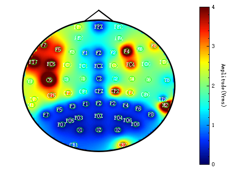
最终得到如下这种形式的效果:

实现方法
- 以Qt为UI框架
- 采用第三方库QCustomplot, 因为这个库使用起来很方便,只需要导入 .h 和 .cpp 文件就行,无需编译成动态链接库。
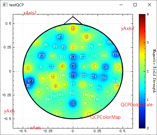
首先,我们对QCustomplot所呈现出的图像有个基础的认识,要实现colormap需要用到的地方我在图中标注了下,主要包括。
- 坐标轴的隐藏(看个人需求)
- 创建一个QCPColorMap类,用于实现上边所说的 drawColorMap 功能
- 创建一个图标尺,用来显示颜色的区间

上边的三步对应程序:
// configure axis rect:
    m_customPlot = new QCustomPlot(this);
    m_customPlot->setInteractions(QCP::iRangeDrag|QCP::iRangeZoom); // this will also allow rescaling the color scale by dragging/zooming
    m_customPlot->axisRect()->setupFullAxesBox(true);
    //隐藏坐标,上下左右
    m_customPlot->xAxis->setVisible(true);
    m_customPlot->yAxis->setVisible(true);
    m_customPlot->xAxis2->setVisible(true);
    m_customPlot->yAxis2->setVisible(true);

    // set up the QCPColorMap:
    m_colorMap = new QCPColorMap(m_customPlot->xAxis, m_customPlot->yAxis);
    // add a color scale:
    m_colorScale = new QCPColorScale(m_customPlot);
    m_customPlot->plotLayout()->addElement(0, 1, m_colorScale); // add it to the right of the main axis rect
    m_colorScale->setType(QCPAxis::atRight); // scale shall be vertical bar with tick/axis labels right (actually atRight is already the default)
    m_colorMap->setColorScale(m_colorScale); // associate the color map with the color scale
    // set the color gradient of the color map to one of the presets:
    m_colorMap->setGradient(QCPColorGradient::gpJet);
这里引入了一个 QCPColorGradient 的概念,我们不难想到这样一个问题:加入值为0时颜色是蓝色,值为10时颜色是红色,那值为5时颜色是什么?这就是 QCPColorGradient 要做的事了。
难道就这么简单?
假如我们要绘制的图像可以分为 400 * 300 个网格分布,按常理来说只需要遍历这些网格并设置颜色就行了,但是实际情况往往是我们获取到的数据很少,
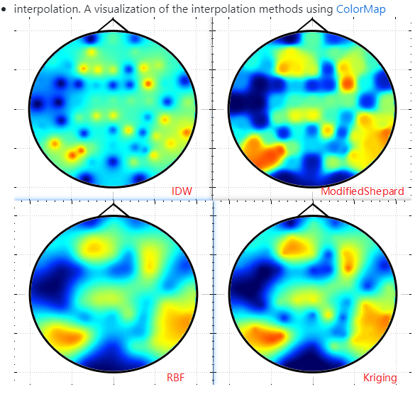
比如只有64个位置,如何扩充到 400 * 300 这么大的格子里呢,该如何插值呢?
不难想象,离这些点越近的格子受到这个点影响越大,反之越小。
距离,关键词为距离,令距离为r,则r代表着插值方式是线性的,改为r2则是曲线的,效果更佳平滑,r3, r^4 以此类推
为了简化计算,采用距离的平方作为权重,只需累加已知的点在未知点的权重即可:
for(int i = 0; i < datax; ++i){
    for(int j = 0; j < datay; ++j){
        m_colorMap->data()->cellToCoord(i, j, &x, &y);
        //计算权重值
        double sum = 0.0;
        for(int k = 0; k < m_channelAxis.size(); ++k){
            //(x, y) 为 (i, j) 在 colormap坐标系下的映射
            auto& point = m_channelAxis[k];
            double rr = (point.x() - x) * (point.x() - x) + (point.y() - y) * (point.y() - y);
            sum += 1 / rr;
            m_channelWeight[i][j][k] = 1 / rr;
        }
        for(int k = 0; k < m_channelAxis.size(); ++k){
            m_channelWeight[i][j][k] /= sum;
        }
    }
}
这样我们就把所有网格对应的颜色值计算出来了,时间复杂度 O(width * height * points)。
等等,这个复杂度貌似很大?400 * 300 * 64 = 7,680,000。如果你看过根据数据范围推测算法复杂度这篇文章,
并且在leetcode刷了刷题,就知道700万这个量级是很大的啦,放leetcode跑肯定超时。
因此我们需要需要优化时间复杂度。
时间复杂度优化
如果搞过图像处理估计你已经知道要怎么优化了,上面的问题等价为 : 已知一幅小尺寸图,如何放大成大尺寸图。
没错,小尺寸。我们上面的网格400 * 300太大了,如果是算 40 * 30 呢?瞬间计算次数就小了有没有!算完之后我们再给他放大嘛。
这里采用双线性插值的方法:
for (int i = 0; i < datax - 1; i++)
    {
        for (int j = 0; j < datay - 1; j++)
        {
            double V1 = m_matrix1[i][j];
            double V2 = m_matrix1[i + 1][j];
            double V3 = m_matrix1[i + 1][j + 1];
            double V4 = m_matrix1[i][j + 1];
            for (int m = 0; m < ratex; m++)
            {
                for (int n = 0; n < ratey; n++)
                {
                    int x = i * ratex + m, y = j * ratey + n;
                    if(m_inCircle[x][y] == false) continue;
                    m_matrix[x][y] = doubleLinear(m, n, ratex, ratey, V1, V2, V3, V4);
                    m_colorMap->data()->setCell(x, y, m_matrix[x][y]);
                }
            }
        }
    }
double HotPlot::doubleLinear(int m, int n, int X, int Y, double V1, double V2, double V3, double V4)
{
    return (m * n * (V3 - V4 - V2 + V1) + X * n * (V4 - V1) + m * Y * (V2 - V1)) / (X * Y) + V1;
}
再来看看现在的计算量 :40 * 30 * 64 + 400 * 300 = 196800,由700万降到了20万!当然,算的少了多多少少会对图像质量有影响,我们适当在复杂度和图像效果上做一些均衡吧。


