
Nvidia SDK11 之 PNPatches(细化算法技术学习)
PN-Triangles (也称作N-patches) 是比较流行的处理粗糙模型细分算法技术,PN-Triangles算法能够将低分辨率模型转化为弯曲表面,该表面然后可以被重新绘制成由“高精曲面细分”的三角形所组成的网格,经常借助于Tessellation (曲面细分) 技术创建外观更加平滑的模型。
在当今游戏中,我们认为理所当然的大量视觉假象都可以借助此类算法来消除。这些视觉假象包括人物关节处呈现块状图案、汽车轮子呈多边形外观以及面部特征粗糙。
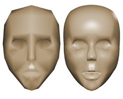
图1 曲面细分技术
无需手工输入,PN-Triangles 可实现游戏人物的自动平滑。几何与光照逼真度均能够得到提升。
DirectX 11 最大新特性 就是融入了Tessellation (曲面细分) 技术,从本质上讲,曲面细分技术是一种将多边形分解成更加细小的碎片以提升几何逼真度的方法。例如,如果处理一个正方形并将其沿对角线切开,那么实际上就是将这一正方形“曲面细分”成为两个三角形。就其本身而言, Tessellation (曲面细分) 并不能提升半点逼真度。例如,在游戏中,一个正方形被渲染成为两个三角形还是两千个三角形都是无关紧要的。只有在使用新三角形来描述新信息时, Tessellation (曲面细分) 才能提升逼真度。
应用曲面细分技术在对基础模型局部任意一个三角图形图元进行细分更细小的三角形图元的过程中,会生成许多新的控制点,如图所示b201、b102、b012等这些控制点在流水线作业过程中经过曲面细分技术之后会重新装配中新的三角形属性描述图元信息。
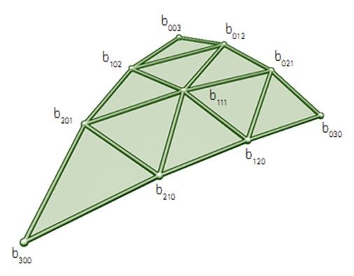
图2 Pn triangle 一个特殊的贝塞尔曲面
置换贴图(displacement mapping)。也有翻译成“位移映射”,似乎更准确。位移映射是同凹凸贴图,法线贴图,切线贴图相区别的另一种制造凹凸细节的技术,它使用一个高度贴图制造出几何物体表面上点的位置被替换到另一位置的效果。这种效果通常是让点的位置沿面法线移动一个贴图中定义的距离。它使得贴图具备了表现细节和深度的能力,且可以同时允许自我遮盖,自我投影和呈现边缘轮廓。
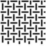

图3 置换贴图应用实例
当一个置换贴图 (左) 应用到平面上时,所生成的表面 (右) 就会表现出置换贴图中所编码的高度信息。
高模与低模+曲面细分+置换贴图的区别
高模的Triangles和quadrilateral有时候高达几千万个面,这样的模型放到游戏引擎里肯定是妥妥跑不动的,高模的雕刻通常网格分布是均匀的,也就意味着一旦雕刻完成,大部分没有动到的网格就失去了意义,比如一张桌面只在中心位置有个凸起,那么桌面其余的不影响轮廓的网格就成了废面。也就是说高模不能决定模型网格顶点的复杂度,比如一块平面,假如这个平面既不会有动画需求,也没有高低起伏,那么上边有一百万个三角面和2两个三角面是没有任何差别的。
直接在GPU上渲染高模计算量大,其二以目前世面上游戏引擎的光照系统精度也不需要这么高的面数(例如阴影分辨率太低),你会发现往游戏引擎里放一个高模和放一个优化好的低模大部分情况下在渲染结果上区别不大,而前后两者的面数往往差几个数量级。
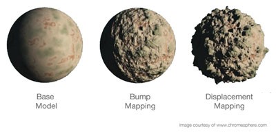
图4 几种贴图技术差别
那么游戏里边有没有比较“廉价”的方案来表现网格顶点复杂度比较高的模型呢?当下相对流程的就是低模+曲面细分+置换贴图的技术来近似动态的模拟复杂度比较高的高模。即低模通过曲面细分实现更光滑的表面,而由此产生的大量顶点为之后的置换贴图提供实现的数据基础。
用高模烘培得到置换贴图,这张图决定细分出来的顶点被挪动到什么位置,细分越高(定点越多),置换贴图精度越高自然结果也就越接近原始高模。但有个问题,如果初始低模面数非常低,形状与高模差距过大,那细分出的顶点就会被移动很长的距离,贴图就会产生较为明显的拉伸。所以想要以细分+置换贴图获得较好的效果,就需要在制作低模时仔细调配低模的模型结构,也就是很多美术所说的“布线”,但即便是如此你得到的结果肯定也会和高模有区别。
置换贴图和法线贴图
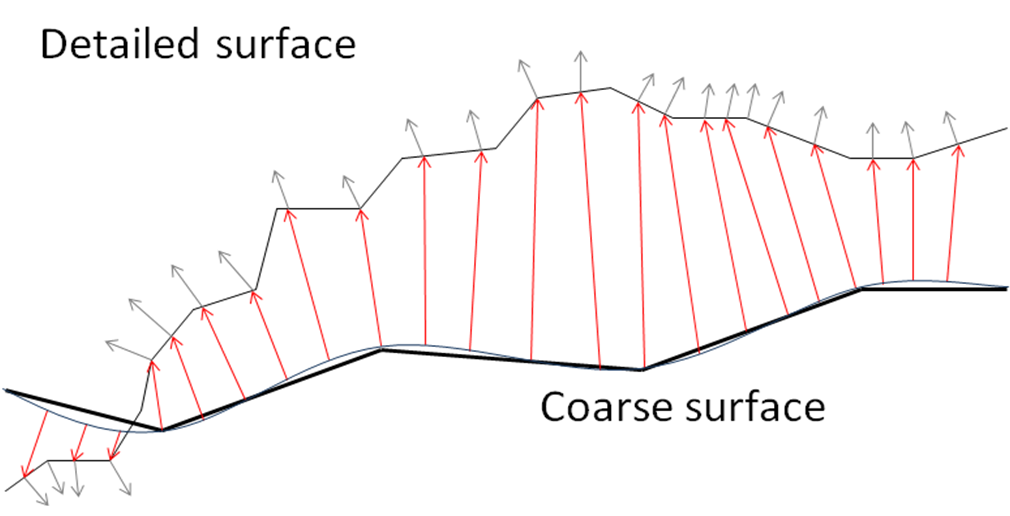
图5 置换贴图原理
粗网格表面上特定点的位移大小取决于粗网格的对应曲面上的光滑法线到无限划分的精细网格(也称为极限面)对应点之间的距离大小,即为红色箭头所示。
上蓝线图像是极限面。红色矢量与光滑法线直接对应于粗糙表面,其长度为位移。这种位移是存储在置换贴图。平滑的法线不需要存储,因为它在渲染时是已知的(它只是一个插值的阴影法线)。黑矢量在红矢量相交的点上是光滑的法线相交的无线细分粗网格细节表面。这些黑法线是存储在法线贴图里。
置换贴图图和法线贴图已经被预编译并存储在DDS文件。它们将被绑定到切线空间,所以这个模型可以在实际使用时仍然可以蒙皮和使用动画,仍然使用相同的法线贴图和位移贴图。
由于置换贴图是关于限制特定细分曲面计算位移,置换贴图应用于PN片细分不同于Catmull-Clark细分算法。在开发这个样本的时候,我们找不到一个工具,可以在PN片细分中生成位移图,所以我们必须开发我们自己的工具。
1 显示法线(Show Normals)
//*****************************************************************************************************
//* RenderVectorsVS域着色器
///*****************************************************************************************************
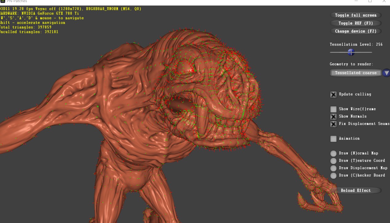
图6 demo 截图
变量定义:
ID3D11Buffer* g_pMeshVertexBuffer;
ID3D11ShaderResourceView* g_pMeshVertexBufferSRV;
ID3D11Buffer* g_pMeshNormalsBuffer;
ID3D11ShaderResourceView* g_pMeshNormalsBufferSRV;
ID3D11Buffer* g_pMeshTangentsBuffer;
ID3D11ShaderResourceView* g_pMeshTangentsBufferSRV;
//The IA will add a vertex id to each vertex for use by shader stages. For each draw call, the vertex id is //incremented by 1. The IA will add a vertex id to each vertex for use by shader stages. For each draw call, //the vertex id is incremented by 1.
float4 RenderVectorsVS(uniform float scale, uint vertexID : SV_VertexID) : SV_Position
{
HSIn_Diffuse output;
int index = vertexID >> 1;
int isOdd = vertexID & 0x1;
float3 position = g_PositionsBuffer.Load(index).xyz;
float4 directionScaled = g_VectorsBuffer.Load(index);
float3 direction = directionScaled.xyz;
//position += direction * directionScaled.w * isOdd;
position += direction * isOdd * scale;
return mul(float4(position, 1.0f), g_ModelViewProjectionMatrix);
}
2 细分着色器
曲面细分阶段,细分为3个阶段:外壳着色器(Hull - Shader)、Tessellation阶段、域着色器阶段(Domain - Shader )。一三阶段可编程,第二阶段不可编程。
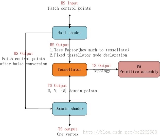
图7 细分流程
2.1 顶点着色器
//*****************************************************************************************************
//*RenderTessellatedDiffuseVS域着色器
//*****************************************************************************************************
HSIn_Diffuse RenderTessellatedDiffuseVS(uint vertexID : SV_VertexID, uniform bool renderAnimated = false)
{
//得到顶点的相关属性信息,顶点着色器之后的顶点patch图元装配阶段做准备
HSIn_Diffuse output;
int2 indices = g_IndicesBuffer.Load(vertexID);
output.position = g_PositionsBuffer.Load(indices.x).xyz;
output.texCoord = g_CoordinatesBuffer.Load(indices.xy);
float4 normalData = g_NormalsBuffer.Load(indices.x);
output.normal = normalData.xyz;
float4 tangentData = g_TangentsBuffer.Load(indices.x);
output.tangent = tangentData.xyz;
#ifdef FIX_THE_SEAMS
output.cornerCoord = g_CornerCoordinatesBuffer.Load(indices.x);
output.edgeCoord = g_EdgeCoordinatesBuffer.Load(vertexID);
#endif
return output;
}
---》input patch
当渲染Tessellation阶段的时候,我们并不把整个low-detail的网格提交到 Input Assembly阶段,而是把顶点(控制点)打包(Patches),然后将集合Patch提交给IA。Direct3D支持1~32个控制点的Patch,如下
pd3dDeviceContext->IASetPrimitiveTopology(D3D11_PRIMITIVE_TOPOLOGY_3_CONTROL_POINT_PATCHLIST);
我们之前输入的是三角形列表,但在这里,因为有了Tessellation着色器,所以虽然还是一个三角形,但把它当作patch处理,三个顶点即为patch的三个控制点。三角形可以看成3个控制点,四边形看成4个控制点。
细分着色器OpenGL参考文章:
http://www.cnblogs.com/magrlemon/p/7290642.html
2.2The Hull Stage (外壳着色器)
//*****************************************************************************************************
//* DiffuseHS 外壳着色器TCS
///*****************************************************************************************************
[domain("tri")] //按triangle 细分
[partitioning("integer")] //细分模式
[outputtopology("triangle_cw")] //细分后输出的语义
[outputcontrolpoints(3)] //该HS着色器对每个patch调用的次数
[patchconstantfunc("DiffuseConstantHS")] //the constant hull shader函数的名字
[maxtessfactor(64.0)] //最大的细分因子。Direct3D支持最多64个
HSIn_Diffuse DiffuseHS( InputPatch<HSIn_Diffuse, 3> inputPatch, uint i : SV_OutputControlPointID)
{
return inputPatch[i]
}
2.3 DiffuseConstantHS
//*****************************************************************************************************
//* Constant Hull Shader着色器
///*****************************************************************************************************
对每个Patch(可以理解为控制点的集合)进行操作,用来输出曲面细分因子的,曲面细分因子能告诉给Tessellation阶段应该把Patch细分成几段,根据三次贝塞尔曲面算法生成六个控制点和一个质心偏移坐标。
HS_CONSTANT_DATA_OUTPUT DiffuseConstantHS( InputPatch<HSIn_Diffuse, 3> inputPatch)
{
HS_CONSTANT_DATA_OUTPUT output;
// tessellation factors are proportional to model space edge length
for (uint ie = 0; ie < 3; ++ie)
{
// g_TessellationFactor / (float)512 * (float)64 的值是把这条边分为几段
#ifdef MESH_CONSTANT_LOD
output.Edges[ie] = g_TessellationFactor / (float)512 * (float)64;
#else
//Patch包含的三个控制点p0,p1钟,两个定点的向量 v0
float3 edge = inputPatch[(ie + 1) % 3].position - inputPatch[ie].position;
//p1 ,p0中点到摄像机的向量
float3 vec = (inputPatch[(ie + 1) % 3].position + inputPatch[ie].position) / 2 - g_FrustumOrigin;
float len = sqrt(dot(edge, edge) / dot(vec, vec));
//该patch中的三个控制点的边向量长度与摄像机到中点向量长度的比值len实时的设置三条边的细分因子output.Edges[(ie+1]%3]
output.Edges[(ie + 1) % 3] = max(1, len * g_TessellationFactor);
#endif
}
//****************************************************************************************************************
//*细分过程为几何提供自动无缝LOD衔接。当表面较远,它的细分因子很小,在图像质量明显没有下降的情况下,性能提高很多。缺点是当//*靠近几何模型,细分能够很好地精细表现,但是性能下降。为了解决这个问题,我们的样本在HS中使用剔除。当表面接近相机时,只有少//*数可见的贴片——由于使用锥裁剪,大部分贴片最终都看不见了
//***************************************************************************************************************
// culling 背面剔除
int culled[4];
for (int ip = 0; ip < 4; ++ip)
{
culled[ip] = 1;
culled[ip] &= dot(inputPatch[0].position - g_FrustumOrigin, g_FrustumNormals[ip].xyz) > 0;
culled[ip] &= dot(inputPatch[1].position - g_FrustumOrigin, g_FrustumNormals[ip].xyz) > 0;
culled[ip] &= dot(inputPatch[2].position - g_FrustumOrigin, g_FrustumNormals[ip].xyz) > 0;
}
if (culled[0] || culled[1] || culled[2] || culled[3]) output.Edges[0] = 0;
#ifdef PN_TRIANGLES
// compute the cubic geometry control points
// edge control points
备注:三角形三条边的6个控制点的计算方式都一样,下面以f3B210为例进行说明。
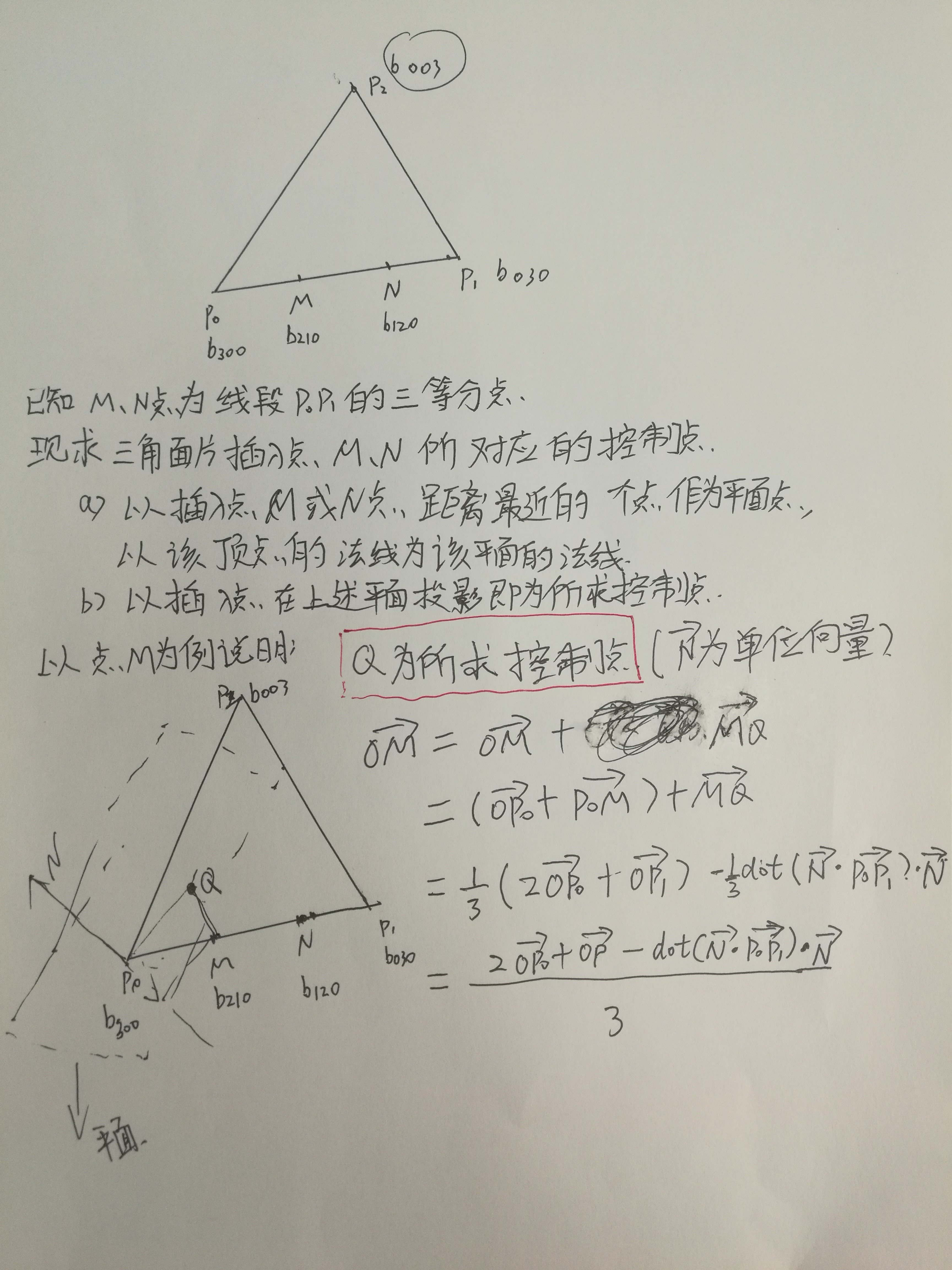
图8 控制点计算
output.f3B210 = ( ( 2.0f * inputPatch[0].position ) + inputPatch[1].position - ( dot( ( inputPatch[1].position - inputPatch[0].position ), inputPatch[0].normal ) * inputPatch[0].normal ) ) / 3.0f;
output.f3B120 = ( ( 2.0f * inputPatch[1].position ) + inputPatch[0].position - ( dot( ( inputPatch[0].position - inputPatch[1].position ), inputPatch[1].normal ) * inputPatch[1].normal ) ) / 3.0f;
output.f3B021 = ( ( 2.0f * inputPatch[1].position ) + inputPatch[2].position - ( dot( ( inputPatch[2].position - inputPatch[1].position ), inputPatch[1].normal ) * inputPatch[1].normal ) ) / 3.0f;
output.f3B012 = ( ( 2.0f * inputPatch[2].position ) + inputPatch[1].position - ( dot( ( inputPatch[1].position - inputPatch[2].position ), inputPatch[2].normal ) * inputPatch[2].normal ) ) / 3.0f;
output.f3B102 = ( ( 2.0f * inputPatch[2].position ) + inputPatch[0].position - ( dot( ( inputPatch[0].position - inputPatch[2].position ), inputPatch[2].normal ) * inputPatch[2].normal ) ) / 3.0f;
output.f3B201 = ( ( 2.0f * inputPatch[0].position ) + inputPatch[2].position - ( dot( ( inputPatch[2].position - inputPatch[0].position ), inputPatch[0].normal ) * inputPatch[0].normal ) ) / 3.0f;
// center control point
float3 f3E = ( output.f3B210 + output.f3B120 + output.f3B021 + output.f3B012 + output.f3B102 + output.f3B201 ) / 6.0f;
float3 f3V = ( inputPatch[0].position + inputPatch[1].position + inputPatch[2].position ) / 3.0f;
output.f3B111 = f3E + ( ( f3E - f3V ) / 2.0f );
#endif
output.Inside = (output.Edges[0] + output.Edges[1] + output.Edges[2]) / 3;
float2 t01 = inputPatch[1].texCoord - inputPatch[0].texCoord;
float2 t02 = inputPatch[2].texCoord - inputPatch[0].texCoord;
//判断z轴朝向 向里还是向外
output.sign = t01.x * t02.y - t01.y * t02.x > 0.0f ? 1 : -1;
return output;
}
//*****************************************************************************************************
//* _RenderPositionAndNormalPS域着色器
///*****************************************************************************************************
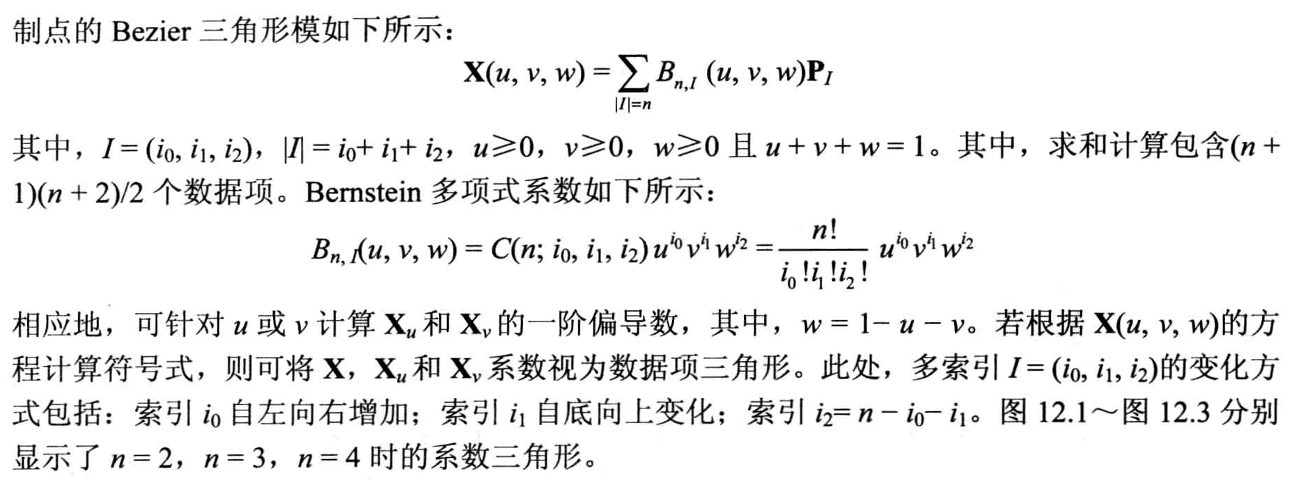
贝塞尔三角形是一种特殊的贝塞尔曲面,它通过控制点和质心坐标信息来确定三次曲面上的点的位置,而PN三角形又是贝塞尔三角形的一种特殊的实现,即PN三角形的控制点信息是依据输入三角形的顶点位置信息和法线信息计算求得,而它的质心坐标则是通过细分着色器来进行插值并输出。
几何控制点的计算
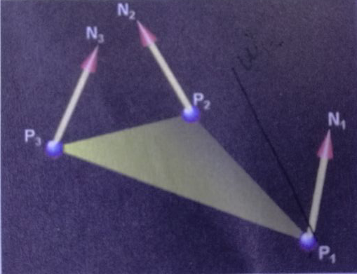
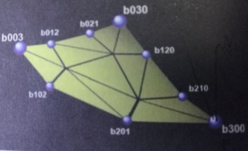
图9 三角形贝塞尔曲面细分示意图
输入渲染管线中的三角面片的信息以顶点为单位,如图 2 所示,P1 ~ P3 是输入顶点的位置信息,N1 ~ N3是输入顶点的法线信息基于这些信息可求得控制点信息。如图3 所示,一个三角面片共有10个控制点,其中 b003,b300,b030是原三角形的 3 个顶点,而其余的7 个控制点则是依据顶点和法线信息插入的,之后根据控制点信息和细分着色器输出的质心坐标信息共同计算出插入点的位置。
//////////////////////////////////////////////////////////////////////////////////////////////////////////
/// DiffuseDS 域着色器
//////////////////////////////////////////////////////////////////////////////////////////////////////////
[domain("tri")]
PSIn_TessellatedDiffuse DiffuseDS( HS_CONSTANT_DATA_OUTPUT input,
float3 barycentricCoords : SV_DomainLocation,
OutputPatch<HSIn_Diffuse, 3> inputPatch )
{
PSIn_TessellatedDiffuse output;
float3 coordinates = barycentricCoords;
// The barycentric coordinates 质心就是面积坐标
float fU = barycentricCoords.x;
float fV = barycentricCoords.y;
float fW = barycentricCoords.z;
// Precompute squares and squares * 3
float fUU = fU * fU;
float fVV = fV * fV;
float fWW = fW * fW;
float fUU3 = fUU * 3.0f;
float fVV3 = fVV * 3.0f;
float fWW3 = fWW * 3.0f;
参考模型二

注意如下:
 |
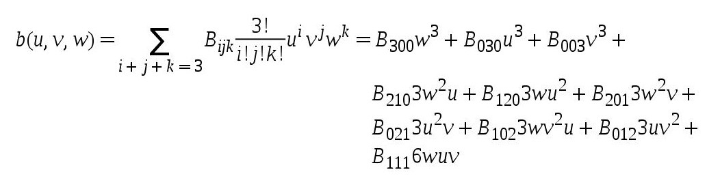
‘u/v/w’ 是质心坐标(他们始终满足等式:u + v + w = 1),‘Bxyz’ 是一组控制点
正如你所见的那样,一组控制点大体就是三角形表面上的一个膨胀表面,将质心坐标带入上面的这个公式,我们就能得到更加接近真实的 3D 表面。
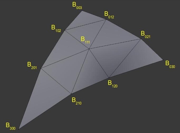
图10 Bezier 三角形面片
// Compute position from cubic control points and barycentric cords
//三角形上的贝塞尔曲面计算公式
float3 position = inputPatch[0].position * fWW * fW + inputPatch[1].position * fUU * fU + inputPatch[2].position * fVV * fV +input.f3B210 * fWW3 * fU + input.f3B120 * fW * fUU3 + input.f3B201 * fWW3 * fV + input.f3B021 * fUU3 * fV +input.f3B102 * fW * fVV3 + input.f3B012 * fU * fVV3 + input.f3B111 * 6.0f * fW * fU * fV;
// Compute normal from quadratic control points and barycentric cords
// 面积坐标的比例因子计算重心的法线
float3 normal = inputPatch[0].normal * coordinates.z + inputPatch[1].normal * coordinates.x + inputPatch[2].normal * coordinates.y;
normal = normalize(normal);
// 面积坐标的比例因子计算重心的纹理坐标
float2 texCoord = inputPatch[0].texCoord * coordinates.z + inputPatch[1].texCoord * coordinates.x + inputPatch[2].texCoord * coordinates.y;
float2 displacementTexCoord = texCoord;
#ifdef FIX_THE_SEAMS
// Edge point 特殊情况
//当质心坐标在三角形的一条边上,coordinates.z对应边的起点到边的终点采用面积坐标比例coordinates.y 或者
//(1- coordinates.y)进行插值。
if(coordinates.z == 0)
displacementTexCoord = lerp(inputPatch[1].edgeCoord.xy, inputPatch[1].edgeCoord.zw, coordinates.y);
else if(coordinates.x == 0)
displacementTexCoord = lerp(inputPatch[2].edgeCoord.xy, inputPatch[2].edgeCoord.zw, coordinates.z);
else if(coordinates.y == 0)
displacementTexCoord = lerp(inputPatch[0].edgeCoord.xy, inputPatch[0].edgeCoord.zw, coordinates.x);
// Corner point特殊情况
//当质心坐标在三角形的顶点上,由面积坐标计算而得
if(coordinates.z == 1)
displacementTexCoord = inputPatch[0].cornerCoord;
else if(coordinates.x == 1)
displacementTexCoord = inputPatch[1].cornerCoord;
else if(coordinates.y == 1)
displacementTexCoord = inputPatch[2].cornerCoord;
#endif
//采用置换贴图,偏移值保存在x变量,面积坐标可能是三角形inputPatch[0],inputPatch[1],inputPatch[2]中的任意一点。
#ifndef IGNORE_DISPLACEMENT
float offset = g_DisplacementTexture.SampleLevel(SamplerLinearClamp, displacementTexCoord, 0).x;
position += normal * offset;
#endif
//计算重心坐标的切线坐标
float3 tangent = inputPatch[0].tangent * coordinates.z + inputPatch[1].tangent * coordinates.x + inputPatch[2].tangent * coordinates.y;
tangent = normalize(tangent);
//齐次投影坐标空间
output.position = mul(float4(position, 1.0f), g_ModelViewProjectionMatrix);
#ifdef SMOOTH_TCOORDS
output.texCoord = displacementTexCoord;
#else
output.texCoord = texCoord;
#endif
output.positionWS = position;
output.normal = normal;
output.tangent = tangent;
output.sign = input.sign;//inputPatch[0].sign;
return output;
}
//////////////////////////////////////////////////////////////////////////////////////////////////////////
/// DiffuseDS 域着色器
//////////////////////////////////////////////////////////////////////////////////////////////////////////
struct PSIn_TessellatedDiffuse
{
float4 position : SV_Position;
float2 texCoord : TEXCOORD0;
float3 positionWS : TEXCOORD1;
float3 normal : TEXCOORD2;
float3 tangent : TEXCOORD3;
float sign : TEXCOROD4;
};
float4 RenderTessellatedDiffusePS(PSIn_TessellatedDiffuse input) : SV_Target
{
#ifdef FLAT_NORMAL
// gpu的pixel shader处理的像素,每次都是一个2x2的quad,对于任意一个属性在rtx(RenderTarget x direction)或//者rty方向上的偏导数,都是可计算的, 因为数据是离散的,所以偏导数的计算就是简单的相减 使用ddx/ddy,切记一定//要确保其2x2区域位于同一三角面的光栅化范围内
float3 dir_x = ddx(input.positionWS);
float3 dir_y = ddy(input.positionWS);
float3 normal = normalize(cross(dir_x, dir_y));
float3 lightDir = normalize(g_CameraPosition - input.positionWS);
#else
float3 normal = normalize(input.normal);
float3 tangent = normalize(input.tangent);
//参考图5 求副法线
float3 bitangent = cross(normal, tangent) * input.sign;
// 构建变换矩阵,将位置坐标从模型空间转换到切线空间
float3x3 tangentBasis = float3x3(tangent, bitangent, normal);
float3 lightDir = normalize(g_CameraPosition - input.positionWS);
// 转换光源方向从模型空间到切线空间
lightDir = normalize(mul(tangentBasis, lightDir));
//采样获取法线纹理值
normal = normalize(g_WSNormalMap.Sample(SamplerLinearClamp, input.texCoord).xyz);
#endif
//在切线空间坐标系下求得该顶点的受光影响
float dotNL = max(dot(normal, lightDir), 0.0f);
float diffuse = dotNL * 0.75f + 0.25f;
float specular = pow(dotNL, 100.0f);
float3 diffuseColor = float3(1.0, 0.5, 0.35) * 0.75;// * 0.75 + (input.sign * 0.5 + 0.5) * 0.25;
float3 color = diffuseColor * diffuse + specular * 0.25;
return float4(color, 0);
}

 浙公网安备 33010602011771号