FOC学习笔记-基于灯哥FOC
1、foc控制技术
现在无刷电机越来越多的进入人们的视野,因为他的控制精度更高,相对直流电机而言可以更稳定的工作等特点,被越来越多的应用于机器人行业,而无刷电机的控制离不开FOC控制。
FOC(field-oriented control)为磁场导向控制,又称为矢量控制(vector control),是一种利用变频器(VFD)控制三相电机的技术,利用调整变频器的输出频率、输出电压的大小及角度,来控制电机的输出。由于处理时会将三相输出电流及电压以矢量来表示,因此称为矢量控制。
下面简单罗列一下一些我获取的资料:
- simplefoc官网
- 灯哥foc
淘宝店:灯哥foc淘宝店
灯哥foc文档:http://dengfoc.com/#/
灯哥foc v3 plus的使用指南:http://dengfoc.com/#/dengfoc/DengFOCV3P硬件文档/2使用指南
- csdn博主专栏
https://blog.csdn.net/loop222?type=blog
这个博主讲了很多关于foc的使用示例,整体来说很丰富。
- 轮腿机器人研究
轮腿机器人现在也很火,这里有一篇文章总结的很不错,这里记录一下:
三款经典的轮式/轮足机器人讲解,以及学习EG2133产生A/B/C驱动电机。个人机器人学习和开发路线(推荐)
另外,在开源社区最常用的FOC项目有:simpleFOC,ODrive,VESC这三种。其中simpleFOC因其简单易用,支持多种硬件平台,很适合新手入门。因此这里我首选simple foc作为入门记录一下。
- foc原理说明
这个我觉得灯哥的视频讲的还行,后期专门补一篇文章把他的视频文字化一下
灯哥手把手教你写FOC算法 系列课程
2、foc原理
FOC的本质是输入需求的电机力矩,之后吧需求的电机力矩转换为三相线的电力输出。
1、无刷电机工作原理
这里主要参考上面说的那个视频,首先最基础的一个原理就是电机的转动,我们知道,电机的转动是因为磁场的变化产生的,在这一点上有刷电机和无刷电机是一样的,有刷电机主要是靠磁场产生力之后利用惯性让电机转到位置之后通过换向片改变磁场方向实现的。而无刷电机也基本相同,目前见得比较多的无刷电机都是外转子的,无刷电机有三根线,可以根据这三根线来改变磁场方向,具体如下:

2、克拉克变换和克拉克逆变换
先总的例举一张foc的算法流程图,foc在计算过程中主要有下面几个流程,这节先说一下卡拉克变换是什么

根据上面的推倒,电机的转动需要三相输出相位差为120°的正弦波,我们把这三相称为ABC三相,但是如果我们直接去控制mos管生成这样一个正弦波不太方便,因为mos管一打开,至少开两个,就是说他们之间是耦合的,因此需要使用其他策略来实现。
克拉克变化就是把这个多变量的耦合降维到单一变量的控制上去,下面是一个降维流程图,先把三个波形降维到三个矢量(波形的变化就变成这三个矢量长短的变化),之后转到一个二维坐标系上去(就是这三个矢量往xy轴上做投影)。

将ia,ib,ic转到α和β坐标系上:

之后得出一个几个变量之间的关系:

转到矩阵表示:

另外,克拉克变换实际上还有个等幅值的形式:

这个等幅值形式可以用下面一个例子来验证,做下面一个电流的假设

这样计算出α和β

这样尽管两个轴重合,但是数值确不一样,这样就是做了一下化简

另外根据基尔霍夫定律,可以省去一个变量,最后得到这样一个表达式:

之后根据上面的式子做一下逆变换

3、帕克变化
经过上面的变化,我们已经把控制ia,ib,ic转到了控制α和β这两个变量上来了,而帕克变换就是将电机旋转的物理状态转化到α和β的一种变换。
帕克变换首先在定子线圈上加上了一个αβ坐标系,之后再αβ上叠加了一个转子,这样αβ坐标系会跟着转子一起转动。如下图所示:

帕克变换又在原来的坐标系上加了一个QD坐标系,让这个坐标系跟着电机一起转动,他和电机的转子固连

这样得到一些新概念,首先是电角度,电角度是这两个坐标系因为转动产生的差角,这样的话如果我们已知电角度的值,就可以在这两个坐标系之间互相转换。(这个值可以由编码器测出来)

转换推导如下:

帕克逆变换,这式子中,电角度由编码器测出,这样,在已知iq和id的情况下,就可以知道α和β,进而获取到abc三相的参数。

而iq和id是固定值,通常一般只控制iq的大小,id设置为0,因为iq是垂直于磁场方向,这个时候是最省力,最能发挥出来控制效果的。
3、foc硬件说明
1、外观
这里我用的是灯哥foc的硬件,大概是下图所示,他是由两个模块组成,这样虽然板子看起来不太好看,但是我觉得这样可以以后换其他芯片驱动(比如stm32来驱动),这样就能更多的了解simplefoc。

2、硬件设计
foc驱动部分,使用了eg2133+mos管的方案

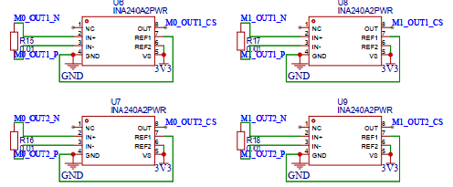
使用ina240做电流检测
dc-dc这里用的是tps54331来稳压到5v,之后给单片机供电用的ams117-3.3芯片

4、基本程序示例
4、1程序来源说明
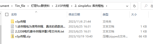
主要参考灯哥例程和官网说明来看,例程如下:
提一下官方文档的位置:https://docs.simplefoc.com/example_from_scratch
看的话从这里开始看:

4、2读取编码器的值
这里只有as5600,因此就只测试了灯哥的as5600的代码,这个编码器大概这样:

关于这个模块的引脚说明如下:

这里需要注意一点就是使用的径向磁铁距离这个模块的距离需要在1mm以内,下图摘自官方说明书:

下面是这个模块的测试例程
#include <SimpleFOC.h>

MagneticSensorI2C sensor0 = MagneticSensorI2C(AS5600_I2C);
MagneticSensorI2C sensor1 = MagneticSensorI2C(AS5600_I2C);
TwoWire I2Cone = TwoWire(0);
TwoWire I2Ctwo = TwoWire(1);

void setup() {


  Serial.begin(115200);
  _delay(750);
//
  I2Cone.begin(19,18, 400000UL);   //SDA0,SCL0
  I2Ctwo.begin(23,5, 400000UL);
  sensor0.init(&I2Cone);
  sensor1.init(&I2Ctwo);
}

void loop() {
   sensor0.update(); // 如果simplefoc库版本为2.20及以上,取消这两行的注释
   sensor1.update();
//  _delay(200);
  Serial.print(sensor0.getAngle());
  Serial.print(" - ");
  Serial.println(sensor1.getAngle());
  Serial.println();
}
需要注意,用这个库读出来的是弧度制的角度
4、3双电机开环速度控制
直接贴代码
#include <SimpleFOC.h>

BLDCMotor motor = BLDCMotor(5); /*实例化电机*/
BLDCDriver3PWM driver = BLDCDriver3PWM(32, 33, 25); /*实例化一个驱动器*/

/*实例化一个串口,这里motor.target 就是要赋值的值*/
Commander command = Commander(Serial);
void doTarget(char *cmd) { command.scalar(&motor.target, cmd); }

void setup()
{
  /*配置驱动器,主要是电源电压和初始化*/
  driver.voltage_power_supply = 12;
  driver.init();
  motor.linkDriver(&driver);/*绑定motor和驱动器*/

  motor.voltage_limit = 1; /*每一项的电压,跟相电阻连起来就能知道电流的限制大小,这尽量小*/
  motor.velocity_limit = 30; /*转速限制*/

  motor.controller = MotionControlType::velocity_openloop; /*配置为开环控制*/

  motor.init(); /*初始化电机*/

  command.add('T', doTarget, "target velocity");

  Serial.begin(115200);
  Serial.println("Motor ready!");
  Serial.println("Set target velocity [rad/s]");
  motor.target = 6.28;
  _delay(1000); /*设置串口信息*/
}
void loop()
{
  motor.move(); /*电机转动*/
  // command.run();
}
这是开环控制,所以硬件上只需要电机即可,无需编码器,也不需要电流检测,接线比较简单,基本上换程序只需要换一下极对数和电压即可。(另外实测在没有负载的情况下效果也是很不错的)
4、4双电机开环位置控制
直接放代码:
#include <SimpleFOC.h>

BLDCMotor motor = BLDCMotor(5);
BLDCDriver3PWM driver = BLDCDriver3PWM(32, 33, 25, 22);

BLDCMotor motor1 = BLDCMotor(5);
BLDCDriver3PWM driver1 = BLDCDriver3PWM(26, 27, 14, 12);

//目标变量
float target_velocity = 5;

//串口指令设置
Commander command = Commander(Serial);
void doTarget(char* cmd) { command.scalar(&target_velocity, cmd); }

//pwm初始化
void PWM_init();

void setup() {
  PWM_init();
  driver.voltage_power_supply = 7.4;
  driver.init();
  motor.linkDriver(&driver);
  motor.voltage_limit = 1;   // [V] !!!!!!!!!!请尽量避免修改此数值,过大的电压电流可能会导致驱动板被烧坏,返修会产生一定费用!!!!!!!!!!
  motor.velocity_limit = 15; // [rad/s]

  driver1.voltage_power_supply = 7.4;
  driver1.init();
  motor1.linkDriver(&driver1);
  motor1.voltage_limit = 1;   // [V] !!!!!!!!!!请尽量避免修改此数值,过大的电压电流可能会导致驱动板被烧坏,返修会产生一定费用!!!!!!!!!!
  motor1.velocity_limit = 15; // [rad/s]


  //开环控制模式设置
  motor.controller = MotionControlType::angle_openloop;
  motor1.controller = MotionControlType::angle_openloop;

  //初始化硬件
  motor.init();
  motor1.init();

  //增加 T 指令
  command.add('T', doTarget, "target velocity");

  Serial.begin(115200);
  Serial.println("Motor ready!");
  Serial.println("Set target velocity [rad/s]");
  _delay(1000);
}

void loop() {
  motor.move(target_velocity);
  motor1.move(target_velocity);

  //用户通讯
  command.run();
}

void PWM_init(){
   pinMode(32, INPUT_PULLUP);
  pinMode(33, INPUT_PULLUP);
  pinMode(25, INPUT_PULLUP);
  pinMode(26, INPUT_PULLUP);
  pinMode(27, INPUT_PULLUP);
  pinMode(14, INPUT_PULLUP);
}
这个开环位置控制和前面说的基本上也差不多,不需要什么其他硬件就可以实现了。
4、4双电机闭环速度控制
#include <SimpleFOC.h>

MagneticSensorI2C sensor = MagneticSensorI2C(AS5600_I2C);
MagneticSensorI2C sensor1 = MagneticSensorI2C(AS5600_I2C);
TwoWire I2Cone = TwoWire(0);
TwoWire I2Ctwo = TwoWire(1);

//电机参数
BLDCMotor motor = BLDCMotor(7);
BLDCDriver3PWM driver = BLDCDriver3PWM(32, 33, 25, 22);

BLDCMotor motor1 = BLDCMotor(7);
BLDCDriver3PWM driver1 = BLDCDriver3PWM(26, 27, 14, 12);

//命令设置
float target_velocity = 0;
float M1_KP = 0;
float M1_KI = 0;
float M2_KP = 0;
float M2_KI = 0;

Commander command = Commander(Serial);
void doTarget(char* cmd) { command.scalar(&target_velocity, cmd); }
void set_m1Kp(char* cmd) { command.scalar(&M1_KP, cmd); }
void set_m1Ki(char* cmd) { command.scalar(&M1_KI, cmd); }
void set_m2Kp(char* cmd) { command.scalar(&M2_KP, cmd); }
void set_m2Ki(char* cmd) { command.scalar(&M2_KI, cmd); }

//I2C初始化
void I2C_init();

void setup() {
  I2C_init();

  //供电电压设置 [V]
  driver.voltage_power_supply = 12;
  driver.init();

  driver1.voltage_power_supply = 12;
  driver1.init();
  //连接电机和driver对象
  motor.linkDriver(&driver);
  motor1.linkDriver(&driver1);

  //FOC模型选择
  motor.foc_modulation = FOCModulationType::SpaceVectorPWM;
  motor1.foc_modulation = FOCModulationType::SpaceVectorPWM;
  //运动控制模式设置
  motor.controller = MotionControlType::velocity;
  motor1.controller = MotionControlType::velocity;

  //速度PI环设置
  motor.PID_velocity.P = 0.021;
  motor1.PID_velocity.P = 0.021;
  motor.PID_velocity.I = 0.12;
  motor1.PID_velocity.I = 0.12;
  //最大电机限制电压
  motor.voltage_limit = 12;//
  motor1.voltage_limit = 12;//

  //速度低通滤波时间常数
  motor.LPF_velocity.Tf = 0.01;
  motor1.LPF_velocity.Tf = 0.01;

  //设置最大速度限制
  motor.velocity_limit = 40;
  motor1.velocity_limit = 40;

  Serial.begin(115200);
  motor.useMonitoring(Serial);
  motor1.useMonitoring(Serial);

  //初始化电机
  motor.init();
  motor1.init();
  //初始化 FOC
  motor.initFOC();
  motor1.initFOC();
  command.add('T', doTarget, "target velocity");
  command.add('A', set_m1Kp, "target velocity");
  command.add('B', set_m1Ki, "target velocity");
  command.add('C', set_m2Kp, "target velocity");
  command.add('D', set_m2Ki, "target velocity");

  Serial.println(F("Motor ready."));
  Serial.println(F("Set the target velocity using serial terminal:"));

}


void loop() {

  motor.PID_velocity.P = M1_KP;
  motor1.PID_velocity.P = M2_KP;
  motor.PID_velocity.I = M1_KI;
  motor1.PID_velocity.I = M2_KI;
  motor.loopFOC();
  motor1.loopFOC();

  motor.move(target_velocity);
  motor1.move(target_velocity);

  command.run();
}


void I2C_init(){
  pinMode(32, INPUT_PULLUP);
  pinMode(33, INPUT_PULLUP);
  pinMode(25, INPUT_PULLUP);
  pinMode(26, INPUT_PULLUP);
  pinMode(27, INPUT_PULLUP);
  pinMode(14, INPUT_PULLUP);

  I2Cone.begin(19,18, 400000UL);
  I2Ctwo.begin(23,5, 400000UL);
  sensor.init(&I2Cone);
  sensor1.init(&I2Ctwo);
  //连接motor对象与传感器对象
  motor.linkSensor(&sensor);
  motor1.linkSensor(&sensor1);
}
这里我把他的pid拿出来了,单独用串口来控制,这样方便调节pid
4、5双电机闭环角度控制
直接贴代码
#include <SimpleFOC.h>

MagneticSensorI2C sensor = MagneticSensorI2C(AS5600_I2C);
MagneticSensorI2C sensor1 = MagneticSensorI2C(AS5600_I2C);
TwoWire I2Cone = TwoWire(0);
TwoWire I2Ctwo = TwoWire(1);

// 电机参数
BLDCMotor motor = BLDCMotor(7);
BLDCDriver3PWM driver = BLDCDriver3PWM(32, 33, 25, 22);

BLDCMotor motor1 = BLDCMotor(7);
BLDCDriver3PWM driver1 = BLDCDriver3PWM(26, 27, 14, 12);

// 命令设置
float target_velocity = 0;
float M1_KP = 0;
float M1_KI = 0;
float M2_KP = 0;
float M2_KI = 0;
float ap = 0;
float ai = 0;

Commander command = Commander(Serial);

void doTarget(char *cmd) { command.scalar(&target_velocity, cmd); }
void set_m1Kp(char *cmd) { command.scalar(&M1_KP, cmd); }
void set_m1Ki(char *cmd) { command.scalar(&M1_KI, cmd); }
void set_m2Kp(char *cmd) { command.scalar(&M2_KP, cmd); }
void set_m2Ki(char *cmd) { command.scalar(&M2_KI, cmd); }
void set_ap(char *cmd) { command.scalar(&ap, cmd); }
void set_ai(char *cmd) { command.scalar(&ai, cmd); }

// I2C初始化
void I2C_init();

void setup()
{
  I2C_init();

  // 供电电压设置 [V]
  driver.voltage_power_supply = 12;
  driver.init();

  driver1.voltage_power_supply = 12;
  driver1.init();
  // 连接电机和driver对象
  motor.linkDriver(&driver);
  motor1.linkDriver(&driver1);

  // FOC模型选择
  motor.foc_modulation = FOCModulationType::SpaceVectorPWM;
  motor1.foc_modulation = FOCModulationType::SpaceVectorPWM;
  // 运动控制模式设置
  motor.controller = MotionControlType::angle;
  motor1.controller = MotionControlType::angle;

  // 速度PI环设置
  motor.PID_velocity.P = 0.021;
  motor1.PID_velocity.P = 0.021;
  motor.PID_velocity.I = 0.12;
  motor1.PID_velocity.I = 0.12;
  // 角度P环设置
  motor.P_angle.P = 20;
  motor.P_angle.D = 0;
  motor1.P_angle.P = 20;
  // 最大电机限制电机
  motor.voltage_limit = 12;  //
  motor1.voltage_limit = 12; //

  // 速度低通滤波时间常数
  motor.LPF_velocity.Tf = 0.01;
  motor1.LPF_velocity.Tf = 0.01;

  // 设置最大速度限制
  motor.velocity_limit = 20;
  motor1.velocity_limit = 20;

  Serial.begin(115200);
  motor.useMonitoring(Serial);
  motor1.useMonitoring(Serial);

  // 初始化电机
  motor.init();
  motor1.init();
  // 初始化 FOC
  motor.initFOC();
  motor1.initFOC();
  command.add('T', doTarget, "target velocity");
  command.add('A', set_m1Kp, "target velocity");
  command.add('B', set_m1Ki, "target velocity");
  command.add('C', set_m2Kp, "target velocity");
  command.add('D', set_m2Ki, "target velocity");
  command.add('E', set_ap, "target velocity");
  command.add('F', set_ai, "target velocity");

  Serial.println(F("Motor ready."));
  Serial.println(F("Set the target velocity using serial terminal:"));
}

void loop()
{
  motor.PID_velocity.P = M1_KP;
  motor1.PID_velocity.P = M2_KP;
  motor.PID_velocity.I = M1_KI;
  motor1.PID_velocity.I = M2_KI;
  motor.P_angle.P = ap;
  motor.P_angle.D = ai;

  // Serial.print(sensor.getAngle());
  // Serial.print(" - ");
  // Serial.print(sensor1.getAngle());
  // Serial.println();
  motor.loopFOC();
  motor1.loopFOC();

  motor.move(target_velocity);
  motor1.move(target_velocity);

  command.run();
}

void I2C_init()
{
  pinMode(32, INPUT_PULLUP);
  pinMode(33, INPUT_PULLUP);
  pinMode(25, INPUT_PULLUP);
  pinMode(26, INPUT_PULLUP);
  pinMode(27, INPUT_PULLUP);
  pinMode(14, INPUT_PULLUP);

  I2Cone.begin(19, 18, 400000UL);
  I2Ctwo.begin(23, 5, 400000UL);
  sensor.init(&I2Cone);
  sensor1.init(&I2Ctwo);
  // 连接motor对象与传感器对象
  motor.linkSensor(&sensor);
  motor1.linkSensor(&sensor1);
}
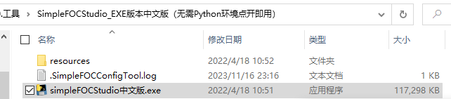
5、simplefoc studio小工具
这个是一个simple foc的调参工具吧,需要给控制器下载特定的程序才能使用,如果是用的灯哥的板子可以直接下载示例程序来实现,这里我用的是这个
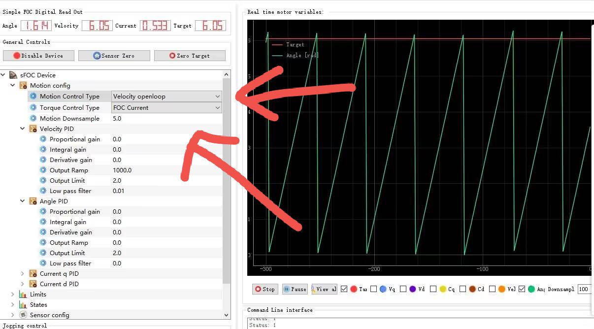
打开是这样的

这个工具我也没玩熟,主要是不知道这些控制模式组合起来是啥意思,这样组合起来有好几种形式,还需要继续学习一下,准备下篇笔记总结。

 浙公网安备 33010602011771号