lspci 详解 pci 拓扑结构 与 pci 树形结构
lspci 详解 pci 拓扑结构 与 pci 树形结构
一、PCIE 拓扑结构
硬盘是大家都很熟悉的设备,一路走来,从HDD到SSD,从SATA到NVMe,作为NVMe SSD的前端接口,PCIe再次进入我们的视野。作为x86体系关键的一环,PCIe标准历经PCI,PCI-X和PCIe,走过近30年时光。其中Host发现与查找设备的方式却一脉沿袭,今天我们先来聊一聊PCIe设备在一个系统中是如何发现与访问的。
首先我们来看一下在x86系统中,PCIe是什么样的一个体系架构。下图是一个PCIe的拓扑结构示例,PCIe协议支持256个Bus, 每条Bus最多支持32个Device,每个Device最多支持8个Function,所以由BDF(Bus,device,function)构成了每个PCIe设备节点的身份证号。
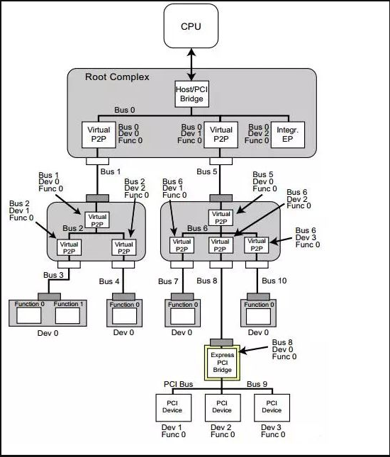
PCIe体系架构一般由root complex,switch,endpoint等类型的PCIe设备组成,在root complex和switch中通常会有一些embeded endpoint(这种设备对外不出PCIe接口)。这么多的设备,CPU启动后要怎么去找到并认出它们呢? Host对PCIe设备扫描是采用了深度优先算法,其过程简要来说是对每一个可能的分支路径深入到不能再深入为止,而且每个节点只能访问一次。我们一般称这个过程为PCIe设备枚举。枚举过程中host通过配置读事物包来获取下游设备的信息,通过配置写事物包对下游设备进行设置。
二、PCIE 设备的遍历过程
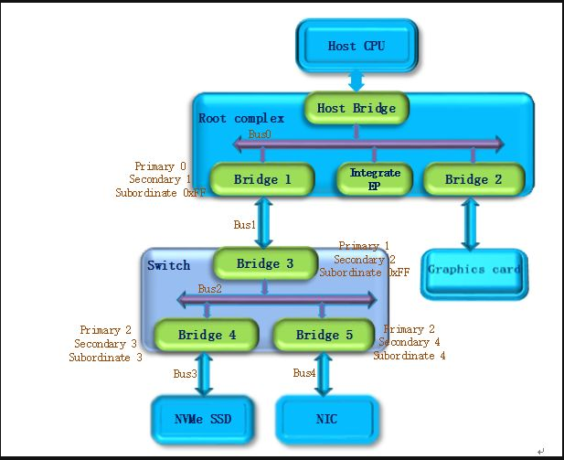
第一步
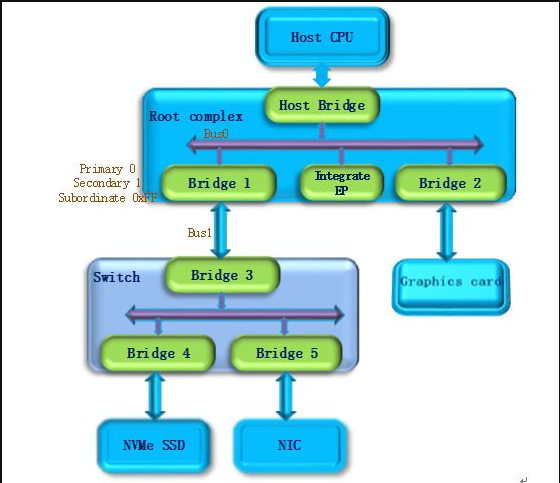
PCI Host主桥扫描Bus 0上的设备(在一个处理器系统中,一般将Root complex中与Host Bridge相连接的PCI总线命名为PCI Bus 0),系统首先会忽略Bus 0上的embedded EP等不会挂接PCI桥的设备,主桥发现Bridge 1后,将Bridge1 下面的PCI Bus定为 Bus 1,系统将初始化Bridge 1的配置空间,并将该桥的Primary Bus Number 和 Secondary Bus Number寄存器分别设置成0和1,以表明Bridge1 的上游总线是0,下游总线是1,由于还无法确定Bridge1下挂载设备的具体情况,系统先暂时将Subordinate Bus Number设为0xFF。
第二步
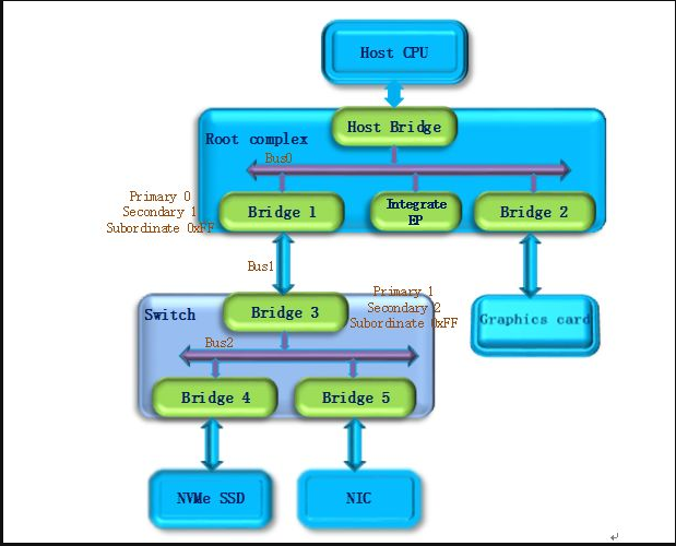
系统开始扫描Bus 1,将会发现Bridge 3,并发现这是一个switch设备。系统将Bridge 3下面的PCI Bus定为Bus 2,并将该桥的Primary Bus Number 和 Secondary Bus Number寄存器分别设置成1和2,和上一步一样暂时把Bridge 3 的Subordinate Bus Number设为0xFF。
第三步
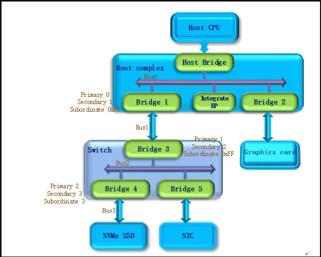
系统继续扫描Bus 2,将会发现Bridge 4。继续扫描,系统会发现Bridge下面挂载的NVMe SSD设备,系统将Bridge 4下面的PCI Bus定为Bus 3,并将该桥的Primary Bus Number 和 Secondary Bus Number寄存器分别设置成2和3,因为Bus3下面挂的是端点设备(叶子节点),下面不会再有下游总线了,因此Bridge 4的Subordinate Bus Number的值可以确定为3。
第四步
完成Bus 3的扫描后,系统返回到Bus 2继续扫描,会发现Bridge 5。继续扫描,系统会发现下面挂载的NIC设备,系统将Bridge 5下面的PCI Bus设置为Bus 4,并将该桥的Primary Bus Number 和 Secondary Bus Number寄存器分别设置成2和4,因为NIC同样是端点设备,Bridge 5的Subordinate Bus Number的值可以确定为4。
第五步
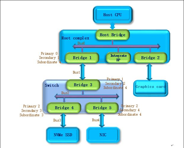
除了Bridge 4和Bridge 5以外,Bus2下面没有其他设备了,因此返回到Bridge 3,Bus 4是找到的挂载在这个Bridge下的最后一个bus号,因此将Bridge 3的Subordinate Bus Number设置为4。Bridge 3的下游设备都已经扫描完毕,继续向上返回到Bridge 1,同样将Bridge 1的Subordinate Bus Number设置为4。
第六步
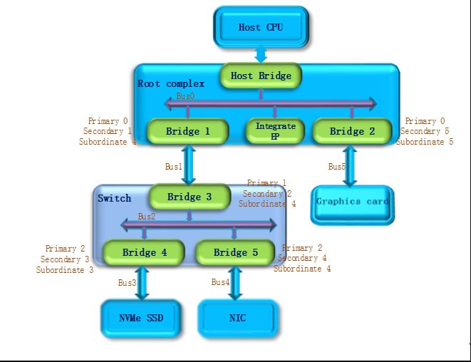
系统返回到Bus0继续扫描,会发现Bridge 2,系统将Bridge 2下面的PCI Bus定为Bus 5。并将Bridge 2的Primary Bus Number 和 Secondary Bus Number寄存器分别设置成0和5, Graphics card也是端点设备,因此Bridge 2 的Subordinate Bus Number的值可以确定为5。
至此,挂在PCIe总线上的所有设备都被扫描到,枚举过程结束,Host通过这一过程获得了一个完整的PCIe设备拓扑结构。
系统上电以后,host会自动完成上述的设备枚举过程。除一些专有系统外,普通系统只会在开机阶段进行设备的扫描,启动成功后(枚举过程结束),即使插入一个PCIe设备,系统也不会再去识别它。
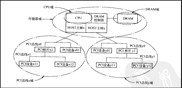
PCI 总线域由 PCI 设备所能直接访问的地址空间组成。在一个处理器系统中,可能存在多个 HOST 主桥,因此也存在多个 PCI 总线域。在上图所示的处理器系统中,具有两个 HOST 主桥,因而在这个处理器系统中存在 PCI 总线 x 和 y 域。
在多数处理器系统中,分属于两个 PCI 总线域的 PCI 设备并不能直接进行数据交换,而需要通过 FSB 进行数据交换。值得注意的是,如果某些处理器的 HOST 主桥支持 Peer-to-Peer 数据传送,那么这个 HOST 主桥可以支持不同 PCI 总线域间的数据传送。
lspci 用于查看 linux 系统下面的pci设备。详细帮助可以通过命令 man lspci 获取详情。
[root@localhost ~]# lspci
00:00.0 Host bridge: Intel Corporation 4th Gen Core Processor DRAM Controller (rev 06)
00:01.0 PCI bridge: Intel Corporation Xeon E3-1200 v3/4th Gen Core Processor PCI Express x16 Controller (rev 06)
00:02.0 VGA compatible controller: Intel Corporation Xeon E3-1200 v3/4th Gen Core Processor Integrated Graphics Controller (rev 06)
00:03.0 Audio device: Intel Corporation Xeon E3-1200 v3/4th Gen Core Processor HD Audio Controller (rev 06)
00:14.0 USB controller: Intel Corporation 8 Series/C220 Series Chipset Family USB xHCI (rev 05)
00:16.0 Communication controller: Intel Corporation 8 Series/C220 Series Chipset Family MEI Controller #1 (rev 04)
00:19.0 Ethernet controller: Intel Corporation Ethernet Connection I217-LM (rev 05)
....
通过 lspci 命令,我们可以得知当前系统上所有的 pci 设备信息。当需要选择特定一个 pci 设备的时候,可以通过 lspci -s bdf 来指定,这个 bdf 就是 lspci 输出的前三列的内容。bdf 的全称其实就是 bus : device . func。
[root@nsa ~]# man lspci
....
 Options for selection of devices
       -s [[[[<domain>]:]<bus>]:][<device>][.[<func>]]
....
根据本小节前面的内容,我们知道 bdf 最前面应该是该 pci 设备所在的 pci 总线域。由于大部分情况下一个系统只有一个 HOST 主桥,所以只有唯一的一个 pci 总线域,此时不需要区分总线域。
四、linux 系统下的 pci 设备目录
由第一、二小节我们知道,pci 的拓扑结构为:pci 桥(包括 HOST 主桥)下面可以延伸出一条 pci 总线,pci 总线上面挂着 pci 设备和 pci 桥。
我们可以通过 /sys/class/pci_bus/ 目录查看 linux 系统下有多少条 pci 总线。
[root@localhost ~]# ls /sys/class/pci_bus/
0000:00  0000:01  0000:02  0000:03  0000:04  0000:05  0000:06  0000:07  0000:08  0000:09
我们也可以通过 /sys/bus/pci/devices/ 目录查看 linux 系统下有多少个 pci 设备(以及相应的设备号 bdf)。
[root@localhost ~]# ls /sys/bus/pci/devices/
0000:00:00.0  0000:00:03.0  0000:00:19.0  0000:00:1c.0  0000:00:1f.0  0000:01:00.0  0000:02:0c.0  0000:04:00.0
0000:00:01.0  0000:00:14.0  0000:00:1a.0  0000:00:1c.1  0000:00:1f.3  0000:02:04.0  0000:02:10.0  0000:09:00.0
0000:00:02.0  0000:00:16.0  0000:00:1b.0  0000:00:1d.0  0000:00:1f.5  0000:02:08.0  0000:02:14.0
系统上电以后,host会自动完成上述的设备枚举过程。除一些专有系统外,普通系统只会在开机阶段进行设备的扫描。当我们安装一个 pci 设备驱动后,可以在 /sys/bus/pci/drivers 目录下找到我们安装的 pci 设备驱动模块。
[root@localhost ~]#  ls /sys/bus/pci/drivers
agpgart-intel  ata_generic  ehci-pci    i915    lpc_ich    ohci-pci   pci-stub  snd_hda_intel     xhci_hcd
agpgart-sis    ata_piix     hsw_uncore  igb     mei_me     pata_acpi  serial    uhci_hcd
agpgart-via    e1000e       i801_smbus  ioapic  mlx5_core  pcieport   shpchp    xen-platform-pci
[root@localhost ~]#
[root@localhost ~]# ls /sys/bus/pci/devices/
0000:00:00.0  0000:00:03.0  0000:00:19.0  0000:00:1c.0  0000:00:1f.0  0000:01:00.0  0000:02:0c.0  0000:04:00.0
0000:00:01.0  0000:00:14.0  0000:00:1a.0  0000:00:1c.1  0000:00:1f.3  0000:02:04.0  0000:02:10.0  0000:09:00.0
0000:00:02.0  0000:00:16.0  0000:00:1b.0  0000:00:1d.0  0000:00:1f.5  0000:02:08.0  0000:02:14.0
[root@localhost platform]# insmod  nsa_dma.ko # 安装驱动模块
[root@localhost platform]#
[root@localhost platform]# ls /sys/bus/pci/drivers  # 多出了一个 nsa_dma 驱动模块
agpgart-intel  ata_generic  ehci-pci    i915    lpc_ich    nsa_dma    pcieport  shpchp         xen-platform-pci
agpgart-sis    ata_piix     hsw_uncore  igb     mei_me     ohci-pci   pci-stub  snd_hda_intel  xhci_hcd
agpgart-via    e1000e       i801_smbus  ioapic  mlx5_core  pata_acpi  serial    uhci_hcd
[root@localhost platform]# ls /sys/bus/pci/devices/ # pci 设备数量不变,因为只会在开机阶段进行 pci 设备扫描
0000:00:00.0  0000:00:03.0  0000:00:19.0  0000:00:1c.0  0000:00:1f.0  0000:01:00.0  0000:02:0c.0  0000:04:00.0
0000:00:01.0  0000:00:14.0  0000:00:1a.0  0000:00:1c.1  0000:00:1f.3  0000:02:04.0  0000:02:10.0  0000:09:00.0
0000:00:02.0  0000:00:16.0  0000:00:1b.0  0000:00:1d.0  0000:00:1f.5  0000:02:08.0  0000:02:14.0
[root@localhost platform]#
五、linux 系统下的 pci 树形结构
通过 lspci -tv 命令,我们可以获得当前 linux 系统下的 pci 设备树。
[root@localhost ~]# lspci -tv
-[0000:00]-+-00.0  Intel Corporation 4th Gen Core Processor DRAM Controller
           +-01.0-[01-07]----00.0-[02-07]--+-04.0-[03]--
           |                               +-08.0-[04]----00.0  Device 1ded:1020
           |                               +-0c.0-[05]--
           |                               +-10.0-[06]--
           |                               \-14.0-[07]--
           +-02.0  Intel Corporation Xeon E3-1200 v3/4th Gen Core Processor Integrated Graphics Controller
           +-03.0  Intel Corporation Xeon E3-1200 v3/4th Gen Core Processor HD Audio Controller
           +-14.0  Intel Corporation 8 Series/C220 Series Chipset Family USB xHCI
           +-16.0  Intel Corporation 8 Series/C220 Series Chipset Family MEI Controller #1
           +-19.0  Intel Corporation Ethernet Connection I217-LM
           +-1a.0  Intel Corporation 8 Series/C220 Series Chipset Family USB EHCI #2
           +-1b.0  Intel Corporation 8 Series/C220 Series Chipset High Definition Audio Controller
           +-1c.0-[08]--
           +-1c.1-[09]----00.0  Intel Corporation I210 Gigabit Network Connection
           +-1d.0  Intel Corporation 8 Series/C220 Series Chipset Family USB EHCI #1
           +-1f.0  Intel Corporation C220 Series Chipset Family H81 Express LPC Controller
           +-1f.3  Intel Corporation 8 Series/C220 Series Chipset Family SMBus Controller
           \-1f.5  Intel Corporation 8 Series/C220 Series Chipset Family 2-port SATA Controller 2 [IDE mode]
[root@localhost ~]#
面我们将结合第一、二小节的内容,解释一下 pci 设备树的结构。
1)
我们知道,只有 pci 桥(包含 HOST 主桥)下,可以新开一条 pci bus 总线。因此,pci 树形结构是以 pci 桥为连接点的。
我们可以通过下面的命令,获取当前 linux 系统下的 pci bus 总线情况:
[root@localhost platform]# ls /sys/class/pci_bus/
0000:00  0000:01  0000:02  0000:03  0000:04  0000:05  0000:06  0000:07  0000:08  0000:09
[root@localhost platform]#
一共有10条 pci bus 总线,开头的 0000:00 就是 HOST主桥下的第一条总线了。
同理,还可以通过命令,获取当前 linux 系统下的 pci 设备号的情况:
[root@localhost platform]# ls /sys/bus/pci/devices/
0000:00:00.0  0000:00:03.0  0000:00:19.0  0000:00:1c.0  0000:00:1f.0  0000:01:00.0  0000:02:0c.0  0000:04:00.0
0000:00:01.0  0000:00:14.0  0000:00:1a.0  0000:00:1c.1  0000:00:1f.3  0000:02:04.0  0000:02:10.0  0000:09:00.0
0000:00:02.0  0000:00:16.0  0000:00:1b.0  0000:00:1d.0  0000:00:1f.5  0000:02:08.0  0000:02:14.0
[root@localhost platform]#
2)
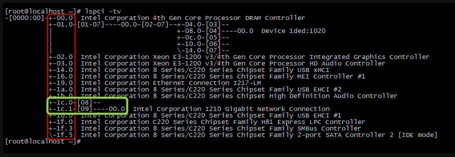
如下图,红色方框中的就是 HOST主桥 bus 0 上的 pci 设备,包括 pci 终端设备和 pci 桥设备。可以看到,绿色方框中的 [00~03].0 ,其中 01.0 之后还有树形结构,所以 01.0 就是 pci 桥设备了;同时可以知道,pci 桥下面会有新开的 pci bus 总线,±01.0-[01-07] 后面的 [01-07] 就是 01.0 pci 桥下面挂接的 pci bus 总线了。 而 [00~03].0 另外三个设备下面没有树形结构,也没有后接 [ ] ,因此就是普通的 pci 终端设备。

接下来,通过下图,可以得知 [00~03].0 对应的设备号,就是 0000:00:00.0,0000:00:01.0,0000:00:02.0,0000:00:03.0。

为了验证我们的结论,我们通过命令查看 0000:00:00.0,0000:00:01.0,0000:00:02.0,0000:00:03.0 对应的设备信息:
[root@localhost platform]# ls /sys/bus/pci/devices/
0000:00:00.0  0000:00:03.0  0000:00:19.0  0000:00:1c.0  0000:00:1f.0  0000:01:00.0  0000:02:0c.0  0000:04:00.0
0000:00:01.0  0000:00:14.0  0000:00:1a.0  0000:00:1c.1  0000:00:1f.3  0000:02:04.0  0000:02:10.0  0000:09:00.0
0000:00:02.0  0000:00:16.0  0000:00:1b.0  0000:00:1d.0  0000:00:1f.5  0000:02:08.0  0000:02:14.0
[root@localhost platform]# ls /sys/class/pci_bus/
0000:00  0000:01  0000:02  0000:03  0000:04  0000:05  0000:06  0000:07  0000:08  0000:09
[root@localhost platform]#
[root@localhost platform]# lspci -s 0000:00:00.0 -v # 0000:00:00.0 为 DRAM 控制器
00:00.0 Host bridge: Intel Corporation 4th Gen Core Processor DRAM Controller (rev 06)
        Subsystem: Intel Corporation 4th Gen Core Processor DRAM Controller
        Flags: bus master, fast devsel, latency 0
        Capabilities: [e0] Vendor Specific Information: Len=0c <?>
        Kernel driver in use: hsw_uncore

[root@localhost platform]# lspci -s 0000:00:01.0 -v  # 0000:00:01.0 为 pci 桥设备
00:01.0 PCI bridge: Intel Corporation Xeon E3-1200 v3/4th Gen Core Processor PCI Express x16 Controller (rev 06) (prog-if 00 [Normal decode])
        Flags: bus master, fast devsel, latency 0, IRQ 24
        Bus: primary=00, secondary=01, subordinate=07, sec-latency=0
        Memory behind bridge: f0000000-f41fffff
        Capabilities: [88] Subsystem: Intel Corporation Xeon E3-1200 v3/4th Gen Core Processor PCI Express x16 Controller
        Capabilities: [80] Power Management version 3
        Capabilities: [90] MSI: Enable+ Count=1/1 Maskable- 64bit-
        Capabilities: [a0] Express Root Port (Slot+), MSI 00
        Capabilities: [100] Virtual Channel
        Capabilities: [140] Root Complex Link
        Kernel driver in use: pcieport
        Kernel modules: shpchp

[root@localhost platform]# lspci -s 0000:00:02.0 -v  # 0000:00:02.0 为 VGA控制器
00:02.0 VGA compatible controller: Intel Corporation Xeon E3-1200 v3/4th Gen Core Processor Integrated Graphics Controller (rev 06) (prog-if 00 [VGA controller])
        Subsystem: Intel Corporation Xeon E3-1200 v3/4th Gen Core Processor Integrated Graphics Controller
        Flags: bus master, fast devsel, latency 0, IRQ 40
        Memory at f4400000 (64-bit, non-prefetchable) [size=4M]
        Memory at e0000000 (64-bit, prefetchable) [size=256M]
        I/O ports at f000 [size=64]
        Expansion ROM at <unassigned> [disabled]
        Capabilities: [90] MSI: Enable+ Count=1/1 Maskable- 64bit-
        Capabilities: [d0] Power Management version 2
        Capabilities: [a4] PCI Advanced Features
        Kernel driver in use: i915
        Kernel modules: i915

[root@localhost platform]# lspci -s 0000:00:03.0 -v  # 0000:00:03.0 为音频设备
00:03.0 Audio device: Intel Corporation Xeon E3-1200 v3/4th Gen Core Processor HD Audio Controller (rev 06)
        Subsystem: Intel Corporation Xeon E3-1200 v3/4th Gen Core Processor HD Audio Controller
        Flags: bus master, fast devsel, latency 0, IRQ 43
        Memory at f4934000 (64-bit, non-prefetchable) [size=16K]
        Capabilities: [50] Power Management version 2
        Capabilities: [60] MSI: Enable+ Count=1/1 Maskable- 64bit-
        Capabilities: [70] Express Root Complex Integrated Endpoint, MSI 00
        Kernel driver in use: snd_hda_intel
        Kernel modules: snd_hda_intel

[root@localhost platform]#
可以看到,确实是 0000:00:01.0 为 pci 桥设备,其他三个为普通 pci 设备。
3)
我们可以进一步验证,1c.0 和 1c.1 是 pci 桥设备,其中 1c.0 下面挂接 08 总线, 1c.1 下面挂接 09 总线, 09 总线下面还有一个 pci 设备:0000:09:00.0。

命令验证 pci 设备信息:
[root@localhost platform]# lspci  -s 0000:00:1c.0 -v #  0000:00:1c.0 为 pci 桥设备
00:1c.0 PCI bridge: Intel Corporation 8 Series/C220 Series Chipset Family PCI Express Root Port #1 (rev d5) (prog-if 00 [Normal decode])
        Flags: bus master, fast devsel, latency 0, IRQ 25
        Bus: primary=00, secondary=08, subordinate=08, sec-latency=0
        I/O behind bridge: 00002000-00002fff
        Memory behind bridge: df200000-df3fffff
        Prefetchable memory behind bridge: 00000000df400000-00000000df5fffff
        Capabilities: [40] Express Root Port (Slot+), MSI 00
        Capabilities: [80] MSI: Enable+ Count=1/1 Maskable- 64bit-
        Capabilities: [90] Subsystem: Intel Corporation 8 Series/C220 Series Chipset Family PCI Express Root Port #1
        Capabilities: [a0] Power Management version 3
        Kernel driver in use: pcieport
        Kernel modules: shpchp

[root@localhost platform]# lspci  -s 0000:00:1c.1 -v  #  0000:00:1c.1 为 pci 桥设备
00:1c.1 PCI bridge: Intel Corporation 8 Series/C220 Series Chipset Family PCI Express Root Port #2 (rev d5) (prog-if 00 [Normal decode])
        Flags: bus master, fast devsel, latency 0, IRQ 26
        Bus: primary=00, secondary=09, subordinate=09, sec-latency=0
        I/O behind bridge: 0000e000-0000efff
        Memory behind bridge: f4800000-f48fffff
        Capabilities: [40] Express Root Port (Slot+), MSI 00
        Capabilities: [80] MSI: Enable+ Count=1/1 Maskable- 64bit-
        Capabilities: [90] Subsystem: Intel Corporation 8 Series/C220 Series Chipset Family PCI Express Root Port #2
        Capabilities: [a0] Power Management version 3
        Kernel driver in use: pcieport
        Kernel modules: shpchp

[root@localhost platform]# lspci  -s 0000:09:00.0 -v  # 0000:09:00.0 为 以太网控制器
09:00.0 Ethernet controller: Intel Corporation I210 Gigabit Network Connection (rev 03)
        Subsystem: DFI Inc Device 100a
        Flags: bus master, fast devsel, latency 0, IRQ 17
        Memory at f4800000 (32-bit, non-prefetchable) [size=512K]
        I/O ports at e000 [size=32]
        Memory at f4880000 (32-bit, non-prefetchable) [size=16K]
        Capabilities: [40] Power Management version 3
        Capabilities: [50] MSI: Enable- Count=1/1 Maskable+ 64bit+
        Capabilities: [70] MSI-X: Enable+ Count=5 Masked-
        Capabilities: [a0] Express Endpoint, MSI 00
        Capabilities: [100] Advanced Error Reporting
        Capabilities: [140] Device Serial Number 00-01-29-ff-ff-97-f7-48
        Capabilities: [1a0] Transaction Processing Hints
        Kernel driver in use: igb
        Kernel modules: igb

[root@localhost platform]#
4)
我们可以留意到,±01.0-[01-07]----00.0-[02-07]–±04.0-[03]-- 这一长串,其实结合 pci 拓扑结构很容易理解。
一个 pci 桥设备只能新开一条 pci bus 总线,pci bus 总线上又可以连接 pci 桥设备,继而又新开 pci bus 总线。同时,pci 扫描采用深度优先算法,因此先扫描到的 pci bus 总线,就优先编号。
所以有如下结论:
±01.0-[01-07] :代表 0000:00 总线上的 0000:00:01.0 设备挂接 [01-07] 七条总线,其中 01 总线是与 0000:00:01.0 pci设备相连接的总线;
[01-07]----00.0-[02-07]: 01 总线下的设备 0000:01:00.0 又是一个 pci 桥设备,下面挂接 [02-07] 六条总线,其中 02 总线是与 0000:01:00.0 pci设备相连接的总线;
[02-07]–±04.0-[03]–
-----------±08.0-[04]----00.0 Device 1ded:1020
-----------±0c.0-[05]–
-----------±10.0-[06]–
------------14.0-[07]–
同理,02 总线下面挂接的都是pci 桥设备,pci 桥设备再新开新的 pci 总线。可以看到,02 总线上的设备 0000:02:08.0 挂接着 04 总线,04 总线上还挂接着 0000:04:00.0 pci 设备。

[root@localhost platform]# lspci  -s  0000:04:00.0  -v
04:00.0 Serial controller: Device 1ded:1020 (prog-if 01 [16450])
        Subsystem: Xilinx Corporation Device 0007
        Flags: bus master, fast devsel, latency 0, IRQ 16
        Memory at f0000000 (32-bit, non-prefetchable) [size=64M]
        Memory at f4000000 (32-bit, non-prefetchable) [size=64K]
        Capabilities: [40] Power Management version 3
        Capabilities: [48] MSI: Enable- Count=1/32 Maskable- 64bit+
        Capabilities: [60] MSI-X: Enable+ Count=33 Masked-
        Capabilities: [70] Express Endpoint, MSI 00
        Capabilities: [100] Advanced Error Reporting
        Kernel driver in use: nsa_dma

[root@localhost platform]#

