AM3358裸片烧写程序-第二部分
7.万事具备后,就开始准备开始第一个程序下载了(有必要说一下,这里只是跑单片机程序,不是跑系统,离系统开发还远着呢)。
7.1下载程序得有源代码才行,StarterWare其实不是软件是TI提供的源代码包,里面有CCS工程、*.C源文件。它自己不能下载,得用CCS加载StarterWare的工程文件,然后用CCS编译、下载才可以。
StarterWare所有例程的工程文件所在目录为:D:\ti\AM335X_StarterWare_02_00_01_01\build\armv7a\cgt_ccs\am335x\beaglebone;所有工程的*.c和*.h源文件所在的目录是:D:\ti\AM335X_StarterWare_02_00_01_01\examples\beaglebone;使用CCS重新编译工程所生成的*.bin可执行文件和*.out下载文件目录是D:\ti\AM335X_StarterWare_02_00_01_01\binary\armv7a\cgt_ccs\am335x\beaglebone。
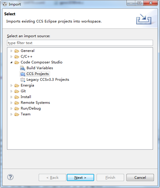
7.2打开CCS6.2.0,点击主菜单File→Import…,弹出如下对话框,并选择其中的“Code Composer Studio -> CCS Projects”,并点击下方的“Next”按钮。
选择“Select search-directory”,并点击右侧的“Browse…”按钮,选择目录D:\ti\AM335X_StarterWare_02_00_01_01\build\armv7a\cgt_ccs\am335x\beaglebone,勾选对话框中选择“Select All”按钮,并选中的“Automatically import referenced projects”选项,点击下方的“Finish”按钮后完成所有AM335x Starter Kit例程的加载。

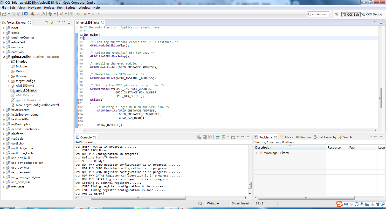
加载后,界面如下图所示
7.3编译、连接、下载程序
首先,选择测试程序,这里我选择了GPIO的测试,因为这个代码简单,可以用万用表直接测量,(这个程序使用的GPIO是GPIO1_23)。单击gpioLEDBlink工程,默认为debug版本,不知道啥原因,debug版本总报错,这里我就将它设置成release版本,如下图所示。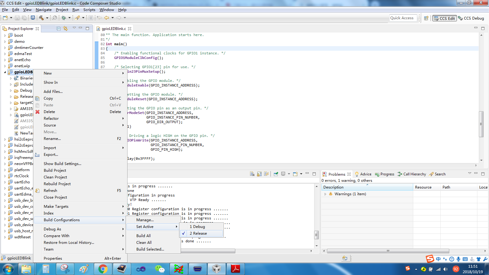
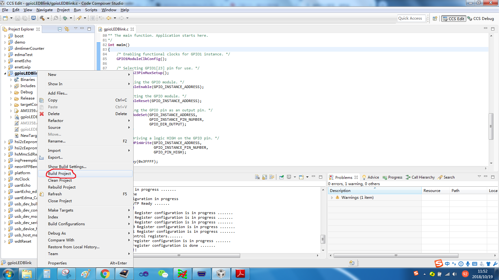
设置完release版本后,可以打开gpioLEDBlink.c程序,这里有熟悉的main函数等等,源代码是TI工程师编写好的,这里只需编译一下,右键工程文件,选择Built project,如下图所示
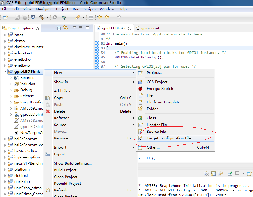
提示编译成功后(一般都会编译成功,如果编译失败,试试debug版本),下一步就要配置目标电路板了,右键工程文件,New->Target Configure File,如下图所示
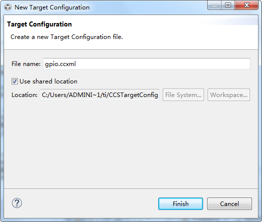
为目标板配置文件起个名字,这里我随便起的gpio,勾选USE share location,勾不勾选无所谓的。
进入配置界面后,选择你自己的仿真器型号,这里我选择XDS100V2 USB,在Board or Decice下拉框里选择AM3358,随后点击Save保存,最后点击Test Coonnection,注意操作顺序,如下图所示
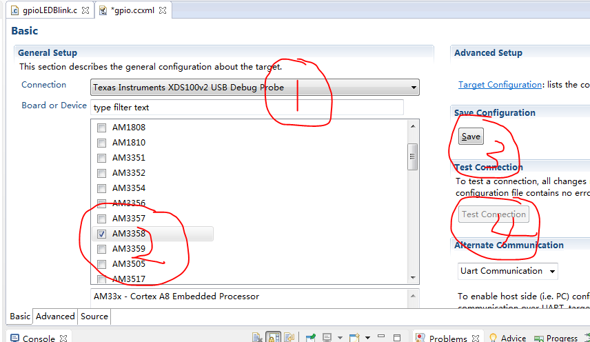
点击Test Connection后,CCS就开始连接目标板JTAG接口,一定要保证先给目标电路板上电,再进行上述操作,否则连接失败。
成功后,会打印如下信息
连接电路板JTAG接口成功后会打印如下信息:
[Start: Texas Instruments XDS100v2 USB Debug Probe_0]
Execute the command:
%ccs_base%/common/uscif/dbgjtag -f %boarddatafile% -rv -o -F inform,logfile=yes -S pathlength -S integrity
[Result]
-----[Print the board config pathname(s)]------------------------------------
C:\Users\ADMINI~1\AppData\Local\TEXASI~1\
CCS\ti\1\0\BrdDat\testBoard.dat
-----[Print the reset-command software log-file]-----------------------------
This utility has selected a 100- or 510-class product.
This utility will load the adapter 'jioserdesusb.dll'.
The library build date was 'Jul 27 2016'.
The library build time was '18:31:37'.
The library package version is '6.0.407.3'.
The library component version is '35.35.0.0'.
The controller does not use a programmable FPGA.
The controller has a version number of '4' (0x00000004).
The controller has an insertion length of '0' (0x00000000).
This utility will attempt to reset the controller.
This utility has successfully reset the controller.
-----[Print the reset-command hardware log-file]-----------------------------
The scan-path will be reset by toggling the JTAG TRST signal.
The controller is the FTDI FT2232 with USB interface.
The link from controller to target is direct (without cable).
The software is configured for FTDI FT2232 features.
The controller cannot monitor the value on the EMU[0] pin.
The controller cannot monitor the value on the EMU[1] pin.
The controller cannot control the timing on output pins.
The controller cannot control the timing on input pins.
The scan-path link-delay has been set to exactly '0' (0x0000).
-----[The log-file for the JTAG TCLK output generated from the PLL]----------
There is no hardware for programming the JTAG TCLK frequency.
-----[Measure the source and frequency of the final JTAG TCLKR input]--------
There is no hardware for measuring the JTAG TCLK frequency.
-----[Perform the standard path-length test on the JTAG IR and DR]-----------
This path-length test uses blocks of 64 32-bit words.
The test for the JTAG IR instruction path-length succeeded.
The JTAG IR instruction path-length is 6 bits.
The test for the JTAG DR bypass path-length succeeded.
The JTAG DR bypass path-length is 1 bits.
-----[Perform the Integrity scan-test on the JTAG IR]------------------------
This test will use blocks of 64 32-bit words.
This test will be applied just once.
Do a test using 0xFFFFFFFF.
Scan tests: 1, skipped: 0, failed: 0
Do a test using 0x00000000.
Scan tests: 2, skipped: 0, failed: 0
Do a test using 0xFE03E0E2.
Scan tests: 3, skipped: 0, failed: 0
Do a test using 0x01FC1F1D.
Scan tests: 4, skipped: 0, failed: 0
Do a test using 0x5533CCAA.
Scan tests: 5, skipped: 0, failed: 0
Do a test using 0xAACC3355.
Scan tests: 6, skipped: 0, failed: 0
All of the values were scanned correctly.
The JTAG IR Integrity scan-test has succeeded.
-----[Perform the Integrity scan-test on the JTAG DR]------------------------
This test will use blocks of 64 32-bit words.
This test will be applied just once.
Do a test using 0xFFFFFFFF.
Scan tests: 1, skipped: 0, failed: 0
Do a test using 0x00000000.
Scan tests: 2, skipped: 0, failed: 0
Do a test using 0xFE03E0E2.
Scan tests: 3, skipped: 0, failed: 0
Do a test using 0x01FC1F1D.
Scan tests: 4, skipped: 0, failed: 0
Do a test using 0x5533CCAA.
Scan tests: 5, skipped: 0, failed: 0
Do a test using 0xAACC3355.
Scan tests: 6, skipped: 0, failed: 0
All of the values were scanned correctly.
The JTAG DR Integrity scan-test has succeeded.
[End: Texas Instruments XDS100v2 USB Debug Probe_0]
/////////////////////////////////////////////////////////////////////////////////////////////////////
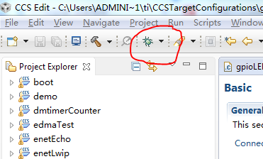
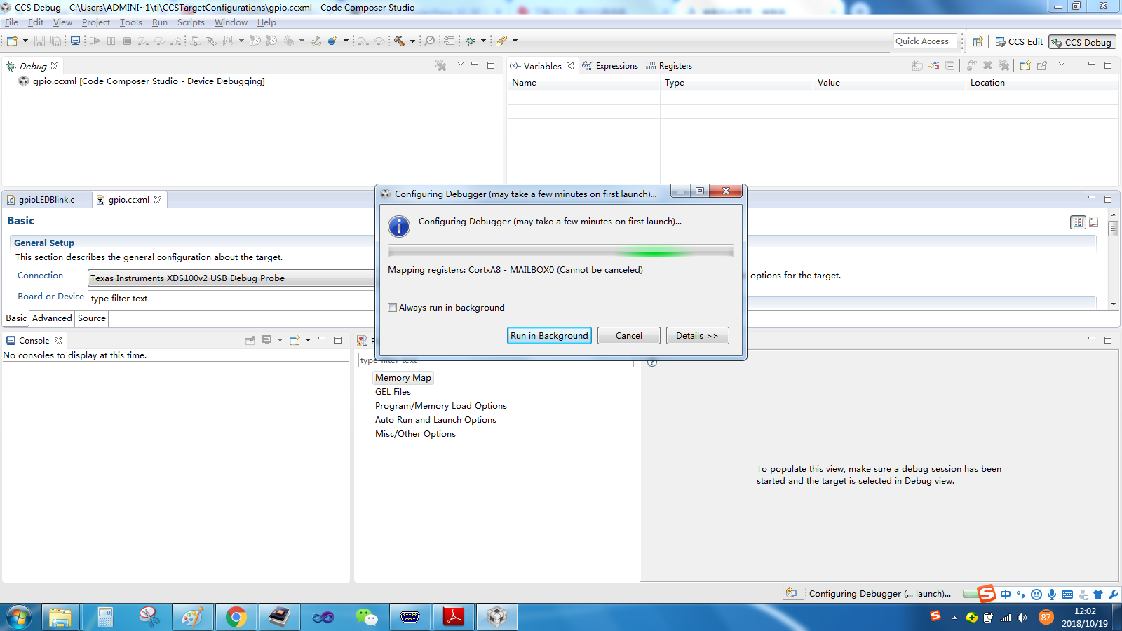
上述步骤只是连接JTAG接口,这是第一步,第一步如果连接不成功,后面的无法继续。在确保Test Connection成功后,点击工具栏的“小虫子”debug图标,如下图所示,进入debug界面
进入debug界面,需要5-8秒中,中间如果有错误弹出,可能是你的目标板已经有Linux系统,(我之前给beaglebone_black开发板下载程序就卡在这了,提示我找不到DAP,网上说得进入开发者模式才行,我没找到怎么进入开发者模式,所以到现在为止beaglebone_black这个板子我还没下载成功),如下图所示
顺利进入debug界面后,进入如下界面
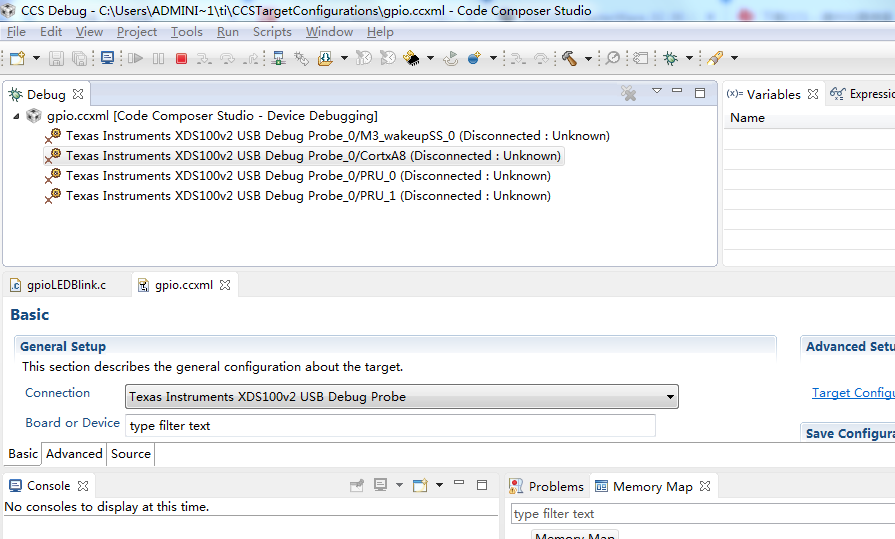
选中下图中的第二项,“Texas Instruments XDS100v2 USB Debug Probe_0/CortexA8”,点鼠
标右键,在出现的菜单中选择“Connect Target”,成功连接以后如下图所示:
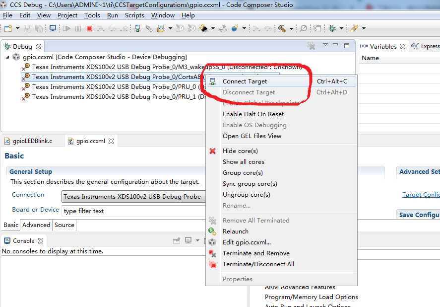
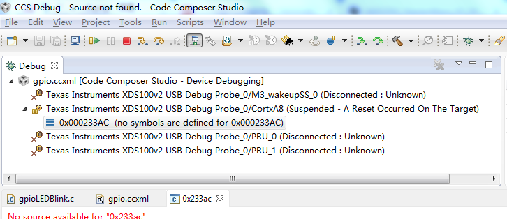
连接电路板芯片成功后,显示如下界面
下一步加载gel 文件。点击Tools→Gel Files,在CCS 主窗口下方会出现一个Gel File 新功
能窗口
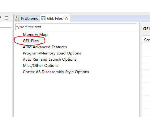
将 鼠 标 放 在上图右下角的GEL Files 窗口中点击右键, 加载gel 文件
(D:\ti\ccsv6\ccs_base\emulation\boards\beaglebone\gel 目录下)
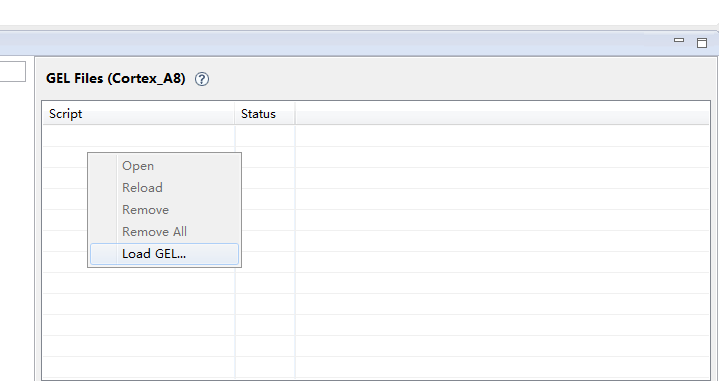
选择beaglebone.gel文件

然后点击主菜单 Scripts – AM335x System Initialization – AM3358_Beaglebone_Initialization。进
行初始化操作。
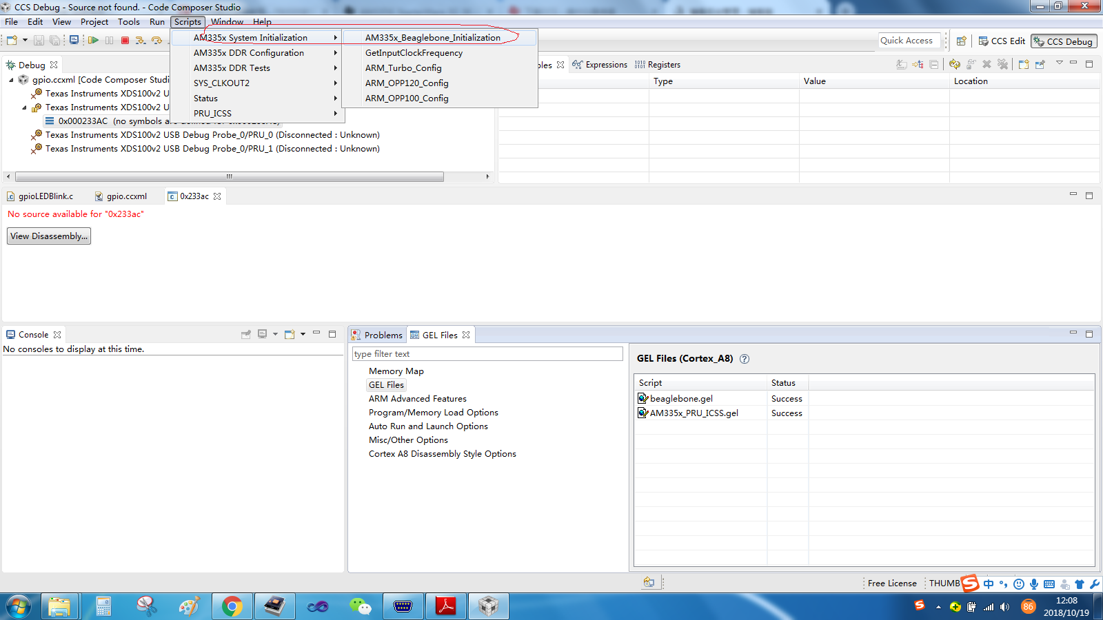
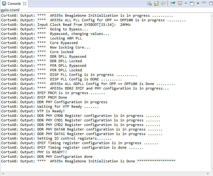
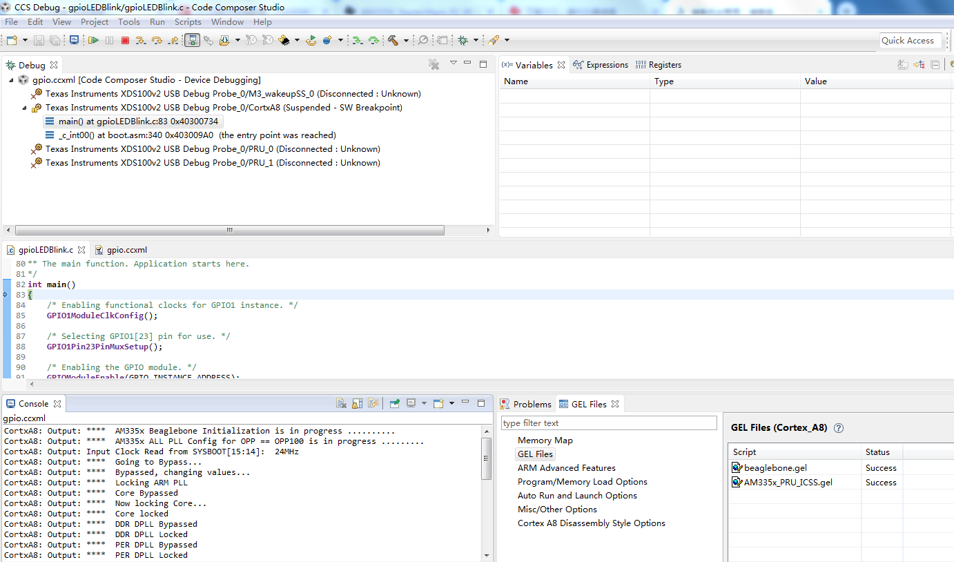
初始化成功后,会有如下提示
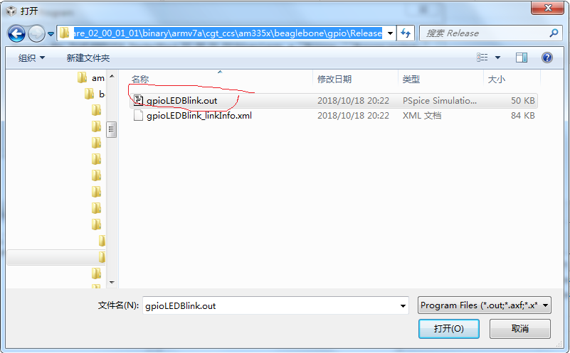
下载程序,如下图所示,通过主菜单的Run 下载程序,选择工程目录下的*.out 文件
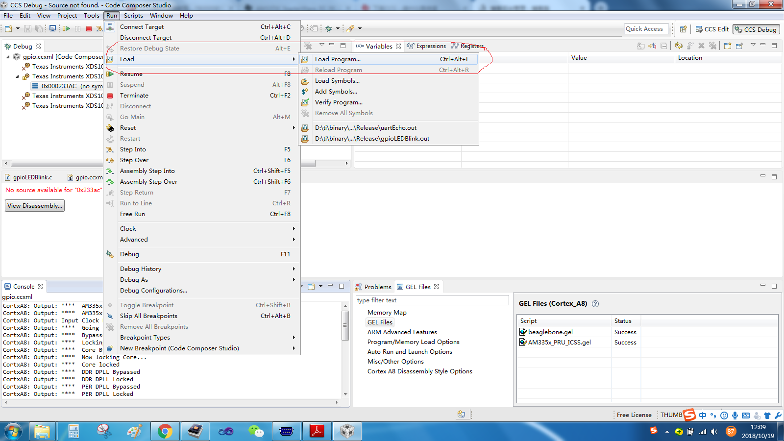
之前编译生成的gpioLEDBlink.out文件,在D:\ti\AM335X_StarterWare_02_00_01_01\binary\armv7a\cgt_ccs\am335x\beaglebone\gpio\Release目录下
加载成功后,显示如下界面
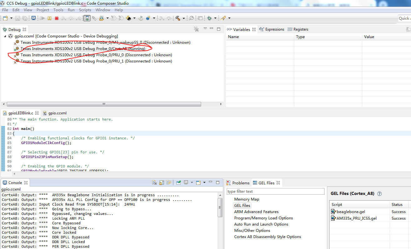
点击工具栏的绿色运行按钮,程序就在芯片中运行起来了,这个时候就可以拿万用表测量一下GPIO1_23那个点的输出电平了,实测是高低电平切换的。


 浙公网安备 33010602011771号