am335x system upgrade kernel ethernet(四)
1 Scope of Document
This document describes ethernet hardware design and porting KZS8081 to uboot and kernel
2 Requiremen
2.1 Function Requirement
Use KZS8081 in am335x, user space use network interface
2.2 Performance Requirement
Support Highest Link-Up Speed( 10/100 Mbps )
3 Hardware Overview
ethernet interface,pin map:
// send signal
AM335X_RMII1_TXD1 -------------MII1_TXD1
AM335X_RMII1_TXD0 -------------MII1_TXD0
AM335X_RMII1_TXEN -------------MII1_TXEN
// receive signal
AM335X_RMII1_RXD0 -------------MII1_RXD0
AM335X_RMII1_RXD1 -------------MII1_RXD1
AM335X_RMII1_RXERR ---------------MII1_RXERR
AM335X_RMII1_REFCLK --------------MII1_REFCLK
// relate with phy addr
AM335X_RMII1_CRS_DV-------------RMII1_CRS
// control signal
AM335X_RMII1_MDIO_CLK -------------MDIO_CLK
AM335X_RMII1_MDIO_DATA------------MDIO_DATA

Figure 1 ethernet interface block diagram
4 Functional Description
4.1 Functional Block Diagram
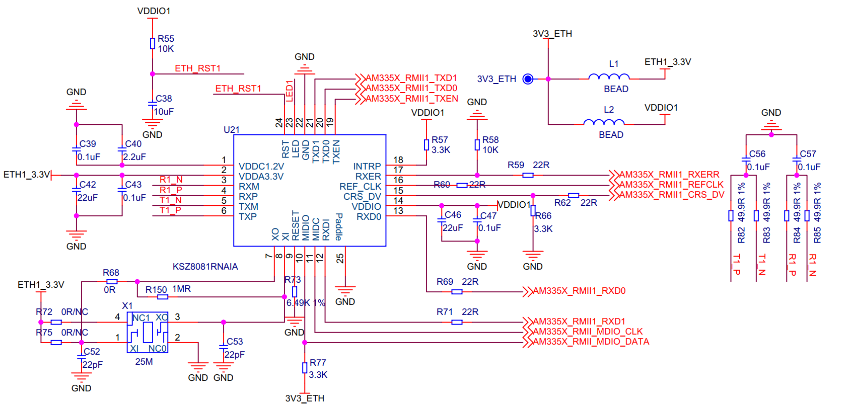
Figure 2 EMAC connect to KSZ8081 phy
AM335X EMAC module connect to KSZ8081 phy
4.2 mdio bus specification
4.2.1 Overview
Most network devices are connected to a PHY by means of a management bus.Different devices use different busses (though some share common interfaces).
The MDIO interface is implemented by two signals:
MDC clock: driven by the MAC device to the PHY.
MDIO data: bidirectional, the PHY drives it to provide register data at the end of a read operation.
The bus only supports a single MAC as the master, and can have up to 32 PHY slaves.
The MDC can be periodic, with a minimum period of 400 ns, which corresponds to a maximum frequency of 2.5 MHz. Newer chips, however, allow faster accesses.
The MDIO requires a specific pull-up resistor of 1.5 kΩ to 10 kΩ, taking into account the total worst-case leakage current of 32 PHYs and one MAC.
4.2.2 Bus timing
Before a register access, PHY devices generally require a preamble of 32 ones to be sent by the MAC on the MDIO line. The access consists of 16 control bits, followed by 16 data bits. The control bits consist of 2 start bits, 2 access type bits (read or write), the PHY address (5 bits), the register address (5 bits), and 2 "turnaround" bits.
During a write command, the MAC provides address and data. For a read command, the PHY takes over the MDIO line during the turnaround bit times, supplies the MAC with the register data requested, then releases the MDIO line.

When the MAC drives the MDIO line, it has to guarantee a stable value 10 ns (setup time) before the rising edge of the clock MDC. Further, MDIO has to remain stable 10 ns (hold time) after the rising edge of MDC.
When the PHY drives the MDIO line, the PHY has to provide the MDIO signal between 0 and 300 ns after the rising edge of the clock. Hence, with a minimum clock period of 400 ns (2.5 MHz maximum clock rate) the MAC can safely sample MDIO during the second half of the low cycle of the clock.
4.2.3 MDIO Packet Format
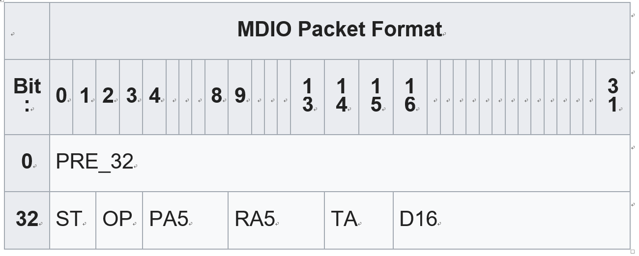
PRE_32
The first field in the MDIO header is the Preamble. During the preamble, the MAC sends 32 bits, all '1', on the MDIO line.
ST
The Start field consists of 2 bits and always contains the combination '01'.
OP
The Opcode consists of 2 bits. There are two possible opcodes, read '10' or write '01'.
PA5
5 bits, PHY address.
RA5
The Register Address field indicates the register to be written to or read from. It is 5 bits long.
TA
The turn-around field is 2 bits long. When data is being written to the PHY, the MAC writes '10' to the MDIO line. When data is being read, the MAC releases the MDIO line.
D16
16 bits, data. This can be sent by either the SME or the PHY, depending on the value of the OP field.
Z
Tristate MDIO.
5 Porting
5.1 Uboot porting
NA
5.2 Kernel porting
am335x.dtsi
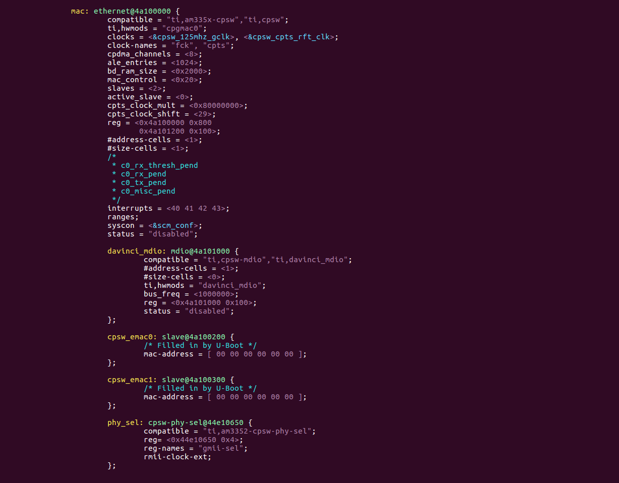
am335x-evm.dts
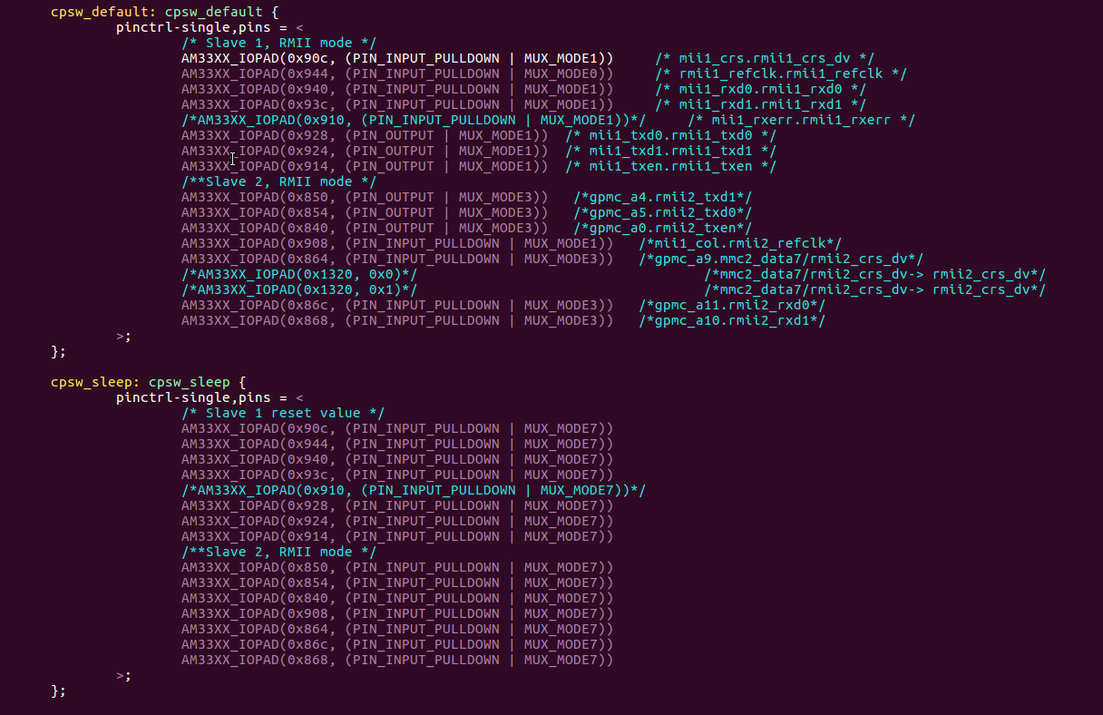

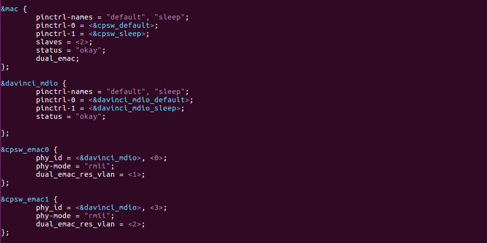
In the new kernel version,we need to change the dts file, to do the pin mux, register phy id , phy connect mode. Then it will work well.
kernel log:
[ 21.514107] Micrel KSZ8081 or KSZ8091 4a101000.mdio:00: attached PHY driver [Micrel KSZ8081 or KSZ8091] (mii_bus:phy_addr=4a101000.mdio:00, irq=POLL)
[ 21.690932] IPv6: ADDRCONF(NETDEV_UP): eth0: link is not ready
[ 21.816198] net eth1: initializing cpsw version 1.12 (0)
[ 21.994187] Micrel KSZ8081 or KSZ8091 4a101000.mdio:03: attached PHY driver [Micrel KSZ8081 or KSZ8091] (mii_bus:phy_addr=4a101000.mdio:03, irq=POLL)
[ 22.106839] IPv6: ADDRCONF(NETDEV_UP): eth1: link is not ready
5.3 Application Interface
The net device interface eth0 eth1
6 Summary
In the KSZ8081 datasheet we can find 32 registers map, the 32 registers is the standard register.
We can ask ourself some question:
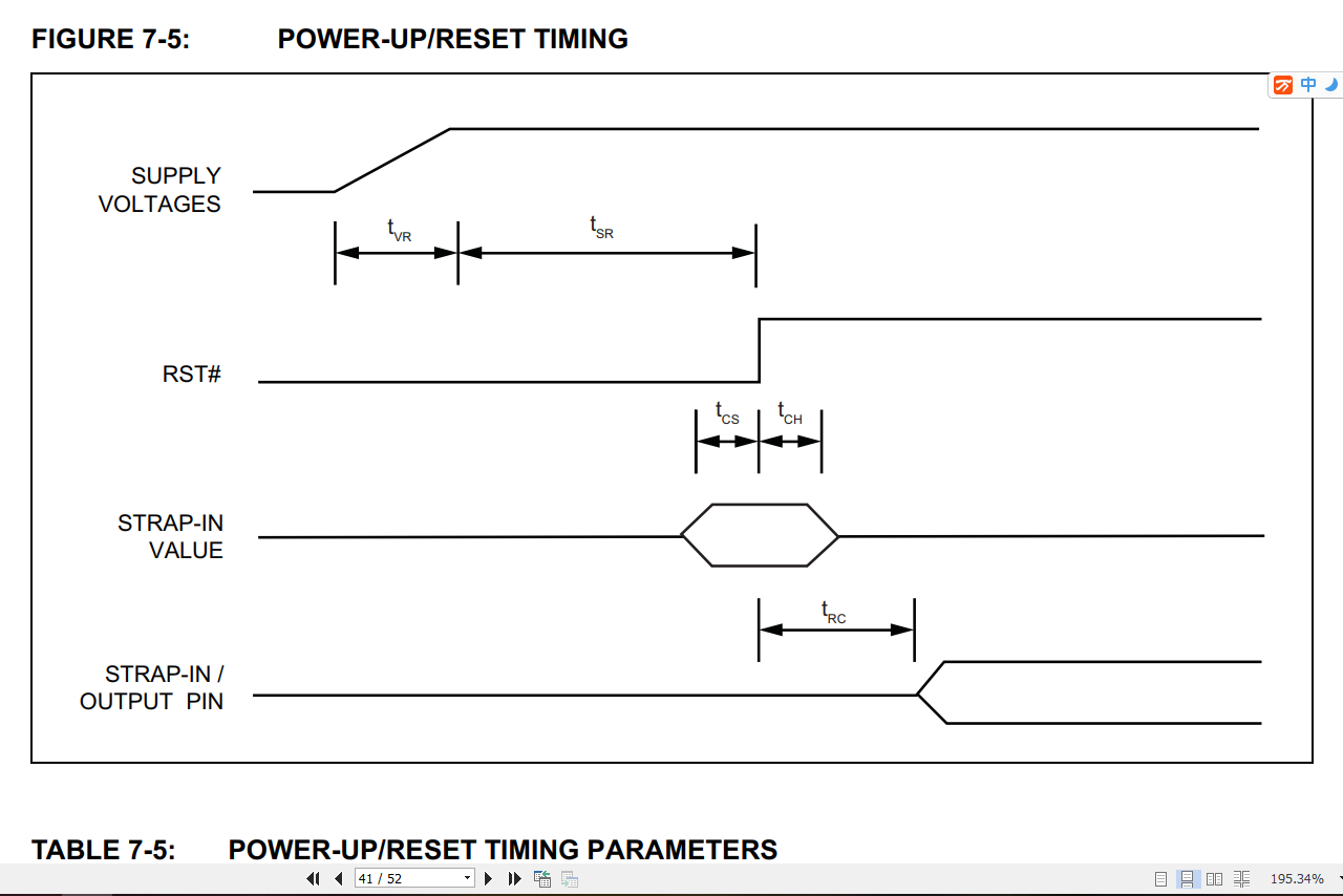
1.How to reset phy?
Reset phy can use gpio base on phy datasheet,such as
2. how to know the phy id?
In phy datasheet we can find our answer.

3. how to cominicate with phy?
Use rmii interface, in the am335x datasheet we can use USERACCESS0/1 register to control rmi interface.
Reading PHY and writing to PHY through the USERACCESS0/1 register using memory browser or
registers window in Code Composer Studio™ is a
effective field-debug feature to troubleshoot PHY issues
(see Table 2).
Table
2. MDIOUSERACCESS0 Register Field Descriptions
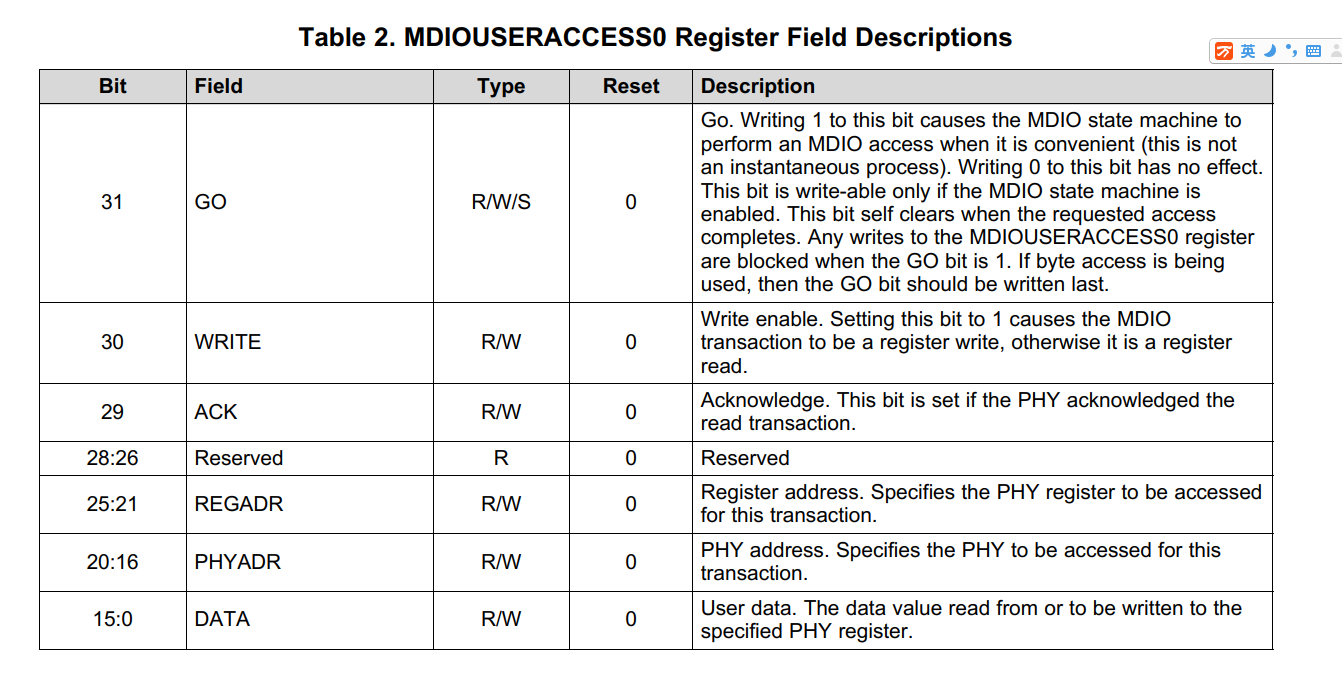
Bit Field Type Reset Description
To read PHY in the memory browser or registers window, follow these steps:
1. Ensure the GO bit in the MDIO user access register (MDIOUSERACCESSn) is
cleared.
2. Write to the GO, REGADR, and PHYADR bits in MDIOUSERACCESSn corresponding to
the PHY and
PHY register to be read.
3. The read data value is available in the DATA bits in MDIOUSERACCESSn after
the module completes
the read operation on the serial bus. Completion of the read operation can be
determined by polling
the GO and ACK bits in MDIOUSERACCESSn. When the GO bit clears, the ACK bit is
set on a
successful read.
To write PHY in the memory browser or registers window, follow these steps:
1. Ensure the GO bit in the MDIO user access register (MDIOUSERACCESSn) is
cleared.
2. Write to the GO, WRITE, REGADR, PHYADR, and DATA bits in MDIOUSERACCESSn
corresponding
to the PHY and PHY register you want to write.
3. The write operation to the PHY is scheduled and completed by the MDIO
module. Completion of the
write operation can be determined by polling the GO bit in MDIOUSERACCESSn for
a 0.
4. how to init phy?
• Connection speed, duplex, and auto-negotiation
•
Auto-MDIX, which determines if a straight or crossover cable is used to connect
to the link partner.
•
Extended full-duplex mode. In extended full-duplex mode, when the PHY is set to
auto-negotiation or
Force
100Base-TX, and the link partner is operated in Force 100Base-TX, the link is
always full
duplex.
When disabled, the decision to work in full-duplex or half-duplex mode follows
IEEE
specification
– half duplex.
•
Detection of transmit error in odd-nibble boundary, which extends TX_EN by one
additional TX_CLK
cycle
and behaves as if TX_ER were asserted during that additional cycle.
•
Additional features like odd nibble insertion and fast link down detection
Most MDIO PHY configuration functions are integrated in the board library of the Processor SDK


