关于GPIO合封引脚以及晶振引脚使用注意事项
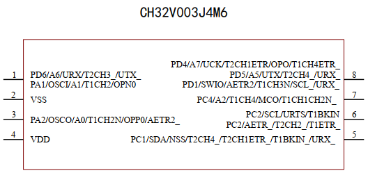
CH32系列某些小封装芯片可能会存在合封引脚,如下图。以下图8脚为例,为PD4、PD5、PD1的合封引脚,其中PD1引脚还作为SWIO下载引脚。若要使用PD4引脚作为普通IO输出高低电平,注意在进行程序配置时需要注意:
(1)PD4引脚按照GPIO输出配置;
(2)合封引脚PD5和PD1要配置为浮空输入模式;
(3)PD1同时作为SWIO下载引脚,要注意关闭SDI下载功能,要注意开启复用时钟,即AFIO时钟。

PD4引脚作为普通IO使用配置代码如下:
/********************************** (C) COPYRIGHT *******************************
 * File Name          : main.c
 * Author             : WCH
 * Version            : V1.0.0
 * Date               : 2023/12/25
 * Description        : Main program body.
 *********************************************************************************
 * Copyright (c) 2021 Nanjing Qinheng Microelectronics Co., Ltd.
 * Attention: This software (modified or not) and binary are used for
 * microcontroller manufactured by Nanjing Qinheng Microelectronics.
 *******************************************************************************/

/*
 *@Note
 *Multiprocessor communication mode routine:
 *Master:USART1_Tx(PD5)\USART1_Rx(PD6).
 *This routine demonstrates that USART1 receives the data sent by CH341 and inverts
 *it and sends it (baud rate 115200).
 *
 *Hardware connection:PD5 -- Rx
 *                     PD6 -- Tx
 *
 */

#include "debug.h"


/* Global define */


/* Global Variable */

/*********************************************************************
 * @fn      USARTx_CFG
 *
 * @brief   Initializes the USART2 & USART3 peripheral.
 *
 * @return  none
 */
void GPIO_CFG(void)
{
    GPIO_InitTypeDef  GPIO_InitStructure = {0};

    RCC_APB2PeriphClockCmd(RCC_APB2Periph_GPIOA | RCC_APB2Periph_GPIOD , ENABLE);
    RCC_APB2PeriphClockCmd(RCC_APB2Periph_AFIO , ENABLE);
    GPIO_PinRemapConfig(GPIO_Remap_SDI_Disable, ENABLE);

    GPIO_InitStructure.GPIO_Pin = GPIO_Pin_1;
    GPIO_InitStructure.GPIO_Speed = GPIO_Speed_30MHz;
    GPIO_InitStructure.GPIO_Mode = GPIO_Mode_IN_FLOATING;
    GPIO_Init(GPIOD, &GPIO_InitStructure);

    GPIO_InitStructure.GPIO_Pin = GPIO_Pin_5;
    GPIO_InitStructure.GPIO_Speed = GPIO_Speed_30MHz;
    GPIO_InitStructure.GPIO_Mode = GPIO_Mode_IN_FLOATING;
    GPIO_Init(GPIOD, &GPIO_InitStructure);

    GPIO_InitStructure.GPIO_Pin = GPIO_Pin_2;
    GPIO_InitStructure.GPIO_Speed = GPIO_Speed_30MHz;
    GPIO_InitStructure.GPIO_Mode = GPIO_Mode_Out_PP;
    GPIO_Init(GPIOA, &GPIO_InitStructure);

    GPIO_InitStructure.GPIO_Pin = GPIO_Pin_4;
    GPIO_InitStructure.GPIO_Speed = GPIO_Speed_30MHz;
    GPIO_InitStructure.GPIO_Mode = GPIO_Mode_Out_PP;
    GPIO_Init(GPIOD, &GPIO_InitStructure);
}

/*********************************************************************
 * @fn      main
 *
 * @brief   Main program.
 *
 * @return  none
 */
int main(void)
{
    u8 i=0,j=0;

    NVIC_PriorityGroupConfig(NVIC_PriorityGroup_1);
    SystemCoreClockUpdate();
    Delay_Init();
#if (SDI_PRINT == SDI_PR_OPEN)
    SDI_Printf_Enable();
#else
//    USART_Printf_Init(115200);
#endif
//    printf("SystemClk:%d\r\n",SystemCoreClock);
//    printf( "ChipID:%08x\r\n", DBGMCU_GetCHIPID() );

    GPIO_CFG();

    while(1)
    {
        Delay_Ms(50); //延时50ms
        GPIO_WriteBit(GPIOA, GPIO_Pin_2, (i==0) ? (i=Bit_SET):(i=Bit_RESET)); //设置PA2引脚状态为低电平
        Delay_Ms(50); //延时50ms
        GPIO_WriteBit(GPIOD, GPIO_Pin_4, (j==0) ? (j=Bit_SET):(j=Bit_RESET)); //设置PD4引脚状态为低电平

    }
}
当使用晶振引脚作为普通GPIO使用时,注意系统主频要切换使用内部晶振进行配置。
分类:
32位MCU学习
标签:
CH32V003;GPIO;合封


【推荐】国内首个AI IDE,深度理解中文开发场景,立即下载体验Trae
【推荐】编程新体验,更懂你的AI,立即体验豆包MarsCode编程助手
【推荐】抖音旗下AI助手豆包,你的智能百科全书,全免费不限次数
【推荐】轻量又高性能的 SSH 工具 IShell:AI 加持,快人一步
· TypeScript + Deepseek 打造卜卦网站:技术与玄学的结合
· Manus的开源复刻OpenManus初探
· AI 智能体引爆开源社区「GitHub 热点速览」
· 从HTTP原因短语缺失研究HTTP/2和HTTP/3的设计差异
· 三行代码完成国际化适配,妙~啊~