将商用器件的spice模型导入到Cadence Virtuoso中仿真
最后修改时间:2024/04/19
1. 需要的文件和软件
- 器件的SPICE网表文件(后缀为.cir)
- Cadence Virtuoso
- Linux端文本编辑器
2. SPICE网表文件
有的器件商家可能提供的模型是PSPICE。PSPICE只是Cadence SPB套件的仿真器而已,内核都是SPICE。
下载好SPICE器件模型(.cir文件)之后,应该打开看一眼,熟悉一下网表文件的构成。
如下是ADI ADA4857的SPICE模型。
* ADA4857 SPICE Macro-model
* Description: Amplifier
* Generic Desc:
* Developed by: CK/ADI
* Revision History:
*   1.1 (01/2013) Updated to new header style
*   1.0 (05/2008)
* Copyright 2008 by Analog Devices, Inc.
*
* Refer to
* http://www.analog.com/Analog_Root/static/techSupport/designTools/
* spiceModels/license/spice_general.html for License Statement.
* Use of this model indicates your acceptance with the terms and
* provisions in the License Statement.
*
* BEGIN Notes:
*
* Not Modeled:
*    Distortion
*    Current noise
*
* Parameters modeled include:
*    closed loop gain and phase vs bandwidth
*    output current and voltage limiting
*    offset voltage (is  non-static, will  vary with gain)
*    ibias (again, is static, will not vary with vcm)
*    slew rate and step response performance
*    (slew rate is based on 10-90% of step response)
*    current on output will be reflected to the supplies
*    vnoise, is included in this version
*    PSRR and CMRR
*
* END Notes
*
* Node assignments
*                non-inverting input
*                |  inverting input
*                |  |  positive supply
*                |  |  |  negative supply
*                |  |  |  |  output
*                |  |  |  |  |
*                |  |  |  |  |
*                |  |  |  |  |
.subckt ADA4857	 1  2  99 50 4

***Differential Stage
Q1	13	12	14	npn
Q2	17	2	16	npn
Rc1	98	13	Rideal	3.200E+00
Rc2	98	17	Rideal	3.200E+00
Re1	14	15	Rideal	3.148E+00
Re2	15	16	Rideal	3.148E+00
Ibias	15	51	1.00E+00
Dcmlim1	18	15	DQUIET
Vcmlim1	18	51	1.026

***Voltage Noise Generation
HVnoise	9	7	Vvnoise	1
VVnoise	501	0	0
DVnoise	501	0	Dvnoise
RVnoise	501	0	0.000855372

***Current Noise Generation on +IN
FInoise1	12	0	VInoise1	1
VInoise1	502	0	0
DInoise1	502	0	DInoise1
RInoise1	502	0	9798.816568

***Current Noise Generation on -IN
FInoise2	2	0	VInoise2	1
VInoise2	503	0	0
DInoise2	503	0	DInoise2
RInoise2	503	0	9798.816568

***Common Mode Injection
Rcm1	1	601	Rideal	100Meg
Rcm2	2	601	Rideal	100Meg
Gcmr	0	602	601	75	1.00E-06
Rcmr1	602	603	Rideal	1Meg
Rcmr2	603	604	Rideal	5.012E+01
Lcmr	604	0	7.977E-06
Ecmr	10	9	603	0	1.000E+00

***Positive Power Supply Rejection
Epsr1	700	0	98	0	1
Rpsr1	700	701	Rideal	1.00E+02
Rpsr2	701	702	Rideal	7.084E-02
Lpsr1	702	0	1.879E-08
Epsr2	11	10	701	0	1

***Negative Power Supply Rejection
Epsr3	703	0	51	0	1
Rpsr3	703	704	Rideal	1.00E+02
Rpsr4	704	705	Rideal	3.983E-02
Lpsr2	705	0	1.268E-08
Epsr4	12	11	704	0	1

***Input Offset and Bias
Vos	1	7	2.000E-03
Ios	1	2	2.500E-08

***Input Impedance
Cinv	2	0	1.00E-12
Cninv	1	0	1.00E-12

***1st Gain and Slew limiting
Gslew	0	101	17	13	1.0000E+00
Rslew	101	0	Rideal	2.50E+02
Dslew1	101	102	DZENER
Dslew2	0	102	DZENER

***Second Gain and Dominant Pole with Output Voltage Limiting
Gp1	51	201	101	0	2.028E-05
Rp1	201	51	Rideal	1.396E+05
Cp1	201	51	1.50E-12
Vlim1	97	206	1.45
Dlim1	201	206	dquiet
Vlim2	207	52	1.45
Dlim2	207	201	dquiet
Esupref1	97	98	51	0	1
Esupref2	52	51	51	0	1

***Second Pole
Gp2	0	202	201	51	1.00E-03
Rp2	202	0	Rideal	1.00E+03
Cp2	202	0	7.95775E-14

***Third Pole
Gp3	0	203	202	0	1.00E-03
Rp3	203	0	Rideal	1.00E+03
Cp3	203	0	1.59155E-16
***Fourth Pole
Gp4	0	204	203	0	1.00E-03
Rp4	204	0	Rideal	1.00E+03
Cp4	204	0	1.59155E-16
***Fifth Pole
Gp5	0	205	204	0	1.00E-03
Rp5	205	0	Rideal	1.00E+03
Cp5	205	0	1.592E-16

***First Zero
Gz1	0	301	205	0	1.00E-03
Rz1	301	302	Rideal	1.00E+03
Lz1	302	0	1.592E-10
***Second Zero
Gz2	0	303	301	0	1.00E-03
Rz2	303	304	Rideal	1.00E+03
Lz2	304	0	1.592E-10
***Third Zero
Gz3	0	305	303	0	1.00E-03
Rz3	305	306	Rideal	1.00E+03
Lz3	306	0	1.59E-10

***Buffer
Gbuf	0	401	305	0	1.00E-04
Rbuf	401	0	Rideal	1.00E+04

***Output with current limiting
Eout	404	0	401	0	1.000E+00
Rout	404	405	RIDEAL	1.000E+00
Lout	405	406	1.00E-19
Cout	406	0	1.00E-22
Voutmon	406	4	0
Dout1	401	407	Dquiet
Vout1	407	406	-5.800E-01
Dout2	408	401	Dquiet
Vout2	406	408	-5.800E-01

***Voltage reference generator
Eref1	98	0	99	0	1
Eref2	51	0	50	0	1
Rref1	98	901	Rideal	100Meg
Rref2	901	51	Rideal	100Meg
Eref3	75	0	901	0	1

***Supply current correction
Iq	99	50	0.0025
Fsup1	99	0	Voutmon	1
*DZsup1	0	802	DZENER2
*Dsup1	99	802	DQUIET
Fsup2	0	50	Voutmon	-1
*DZsup2	804	0	DZENER2
*Dsup2	804	50	DQUIET

***models
.model	Rideal	res	T_ABS=-273
.model	Rnoise	res	T_ABS=27
.model	npn	npn	BF= 249999
.model	dquiet	d
.model	dvnoise	d	KF=5808000
.model	dinoise1	d	KF=3.38
.model	dinoise2	d	KF=3.38
.model	dzener	d	BV=206.464165387408
.model	dzener2	d	BV=50

.ends
*$
需要说明的是:
.subckt声明了一个子模块电路及其端口,也就是说,一个SPICE网表内部是允许写入多个器件的,也就是多个subckt(subcircuit)。.subckt内部就是简单的器件实例化和网络连接。.model声明了模型映射情况。比如以上的model Rideal res T_ABS=-273,意味着上述网表中提到的所有名为Rideal名字的模型,其实都是温度在-273℃绝对零度下的电阻模型。
ADI公司的很多SPICE模型,其端口名称都是数字,如果不打开网表看注释,直接导入的话,symbol端口也是数字命名的,根本无法知道含义是什么。
3. Cadence Virtuoso导入SPICE网表
本部分参考了Cadence官方文档:PSPICE Netlist Support in ADE, Rapid Adoption Kit, June 2018,来源于eetop论坛[1]下载。
3.1. 管理SPICE文件
将SPICE文件放到一个你知道的路径,方便后续引用。
3.2. 建立对应的view
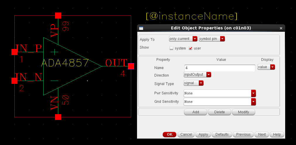
在Virtuoso中先建立器件对应的symbol view,端口名与SPICE网表里的要一致。

上图是我根据ADA4857.cir建立的器件,注意端口名称也和网表内容一样是数字名称。"OUT"等字符串只是为了方便看而加上的注释。
然后在此页面选择File-Save a copy...,另存为spectre view。
3.3. 建立仿真原理图
使用刚刚建立的symbol view画出仿真电路原理图,不再赘述。
3.4. 配置ADE
注意:我只试过ADE L,没有试过ADE XL/GXL。主要原因是因为ADE L仿真时会自动跳出log,比较方便配置和修改。
ADE正常配置就行,没有什么特别的地方。
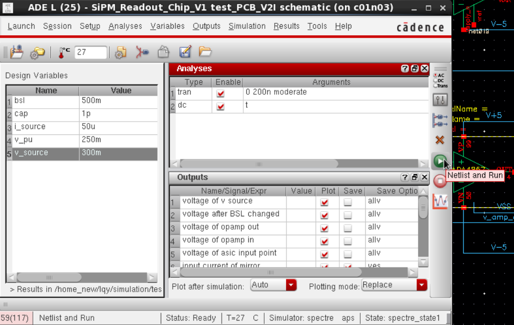
但是要知道的一点是,我们平常直接点这个绿色按钮开始仿真,它的实际含义是"Netlist and Run",所以实际上分为两步:生成网表、运行仿真。如下图所示。

在ADE菜单中点击Simulation,可以分别找到Netlist和Run。后面我们会将这两步分开。
3.5. 生成网表
点击Simulation-Netlist-Create(如果网表已经存在,应该选择Recreate),会弹出生成网表的input.scs。这个就是实际执行仿真时调用的脚本。实际上,上述过程还生成了netlist文件,这个就是网表文件。
3.6. 运行仿真
3.6.1. 先执行一次仿真
点击Simulation-Run,此时应当不能仿真,如下图所示是报错的log。

错误也很容易找到:

这就是说,ADA4857的模型未定义。
请务必翻到log的开头,找到一行:Current working directory: xxx,然后打开这个路径。这就是仿真执行的路径。在这个路径下,应该能找到网表netlist文件和脚本input.scs文件。
3.6.2. 增加调用语句
在input.scs的最后加上定义语句:
pspice_include "xxx/ADA485.cir"
上述xxx是绝对路径,通过这个语句完成PSPICE网表调用。
3.6.3. 重新执行仿真
然后回到ADE页面,点击Simulation-Run(注意,不能重新执行netlist相关命令,不然刚刚添加的那句话就被覆盖了)。发现此时能够成功仿真了。
Cadence ADE PSPICE仿真教程:SPICE MODEL怎么导入virtuoso进行仿真 - Analog/RF IC 设计讨论 - EETOP 创芯网论坛 (原名:电子顶级开发网) ↩︎


【推荐】国内首个AI IDE,深度理解中文开发场景,立即下载体验Trae
【推荐】编程新体验,更懂你的AI,立即体验豆包MarsCode编程助手
【推荐】抖音旗下AI助手豆包,你的智能百科全书,全免费不限次数
【推荐】轻量又高性能的 SSH 工具 IShell:AI 加持,快人一步
· 无需6万激活码!GitHub神秘组织3小时极速复刻Manus,手把手教你使用OpenManus搭建本
· Manus爆火,是硬核还是营销?
· 终于写完轮子一部分:tcp代理 了,记录一下
· 别再用vector<bool>了!Google高级工程师:这可能是STL最大的设计失误
· 单元测试从入门到精通