

Games101现代计算机图形学入门 - 作业1~8 集合含提高项总结
Github 地址 :Games101 作业总结
Games101 官网:Games101 - 现代图形学入门
记录 Games101 Homework 系列 1 ~ 8 及相关作业提高项
环境安装
- 开发环境:Win 10
- IDE:Visual Studio 2022
由于懒得搞 VM,所以直接在 win 平台下开发,主要的依赖如下: - Eigen
- OpenCV
需要先安装 CMake,下载 Eigen 源码和 OpenCV 源码,利用 Cmake 进行源码编译后,将 include 和 dll 配置到 Visual studio 中即可。
作业 0 - 框架搭建
要求
给定一个点 P=(2,1), 将该点绕原点先逆时针旋转 45 ◦ ,再平移 (1,2), 计算出变换后点的坐标(要求用齐次坐标进行计算)。
思路
思路比较简单,定义好仿射变换的矩阵,然后运用到向量上即可。由于是二维平面,运用齐次坐标后得到 3 x 3 的矩阵
利用 Eigen 定义好矩阵后左乘点 p 即可。
作业 1 - MVP 变换
要求
填写一个旋转矩阵和一个透视投影矩阵。给定三维下三个点 v 0 (2.0,0.0,−2.0), v1 (0.0,2.0,−2.0), v2 (−2.0,0.0,−2.0), 你需要将这三个点的坐标变换为屏幕坐标并在屏幕上绘制出对应的线框三角形 (在代码框架中已经提供了 draw_triangle 函数,所以只需要去构建变换矩阵即可)。简而言之,需要进行模型、视图、投影、视口等变换来将三角形显示在屏幕上。在提供的代码框架中,需要完成模型变换和投影变换的部分。
思路
只需要实现如下接口:
Eigen::Matrix4f get_model_matrix(float rotation_angle); Eigen::Matrix4f get_projection_matrix(float eye_fov, float aspect_ratio, float zNear, float zFar);
分别对应 MVP 变换中的 Model Transform 和 Project Transform。只需要分别实现对应的矩阵即可。
[!note]
View Transform 在框架中已经实现好了,因此不需要关注相机的位置。
Model Transform
这里需要实现 Model Transform 的原因是三角形会根据键盘输入旋转,因此需要构建对应三角形每个顶点的变换矩阵。也就是旋转矩阵 。绕指定轴的旋转矩阵在课程中已经推导过了,更详细的可以看 Lecture 3 ~ 4 的 [[Lecture 3 ~ 4 多维变换与MVP#绕 XYZ 旋转|推导过程]] 。
矩阵的构建比较简单,只是需要注意:c++ 的标准接口 sin 和 cos 接收的参数是弧度,因此需要做一次角度 -> 弧度的转换。
Eigen::Matrix4f get_model_matrix(float rotation_angle) { Eigen::Matrix4f model = Eigen::Matrix4f::Identity(); // TODO: Implement this function // Create the model matrix for rotating the triangle around the Z axis. // Then return it. float angle = rotation_angle / 180 * MY_PI; model << std::cos(angle), -std::sin(angle), 0, 0, std::sin(angle), std::cos(angle), 0, 0, 0, 0, 1, 0, 0, 0, 0, 1; return model; }
Projection Transform
接下来要做的是投影变换,需要先做一次透视投影,然后再做正交投影将物体缩放到合适的比例并移动到合适的位置。
- 透视投影的矩阵最终结果和[[Lecture 3 ~ 4 多维变换与MVP#透视投影(Perspective projection)|推导过程]]一致。这里对各个参数进行简单介绍
- eye_fov:视角宽度,这里理解为上下视角或者左右视角的宽度都可以,因为框架中 width/height 的比例为 1
- aspect_ratio:宽高比
- zNear:近平面 Z 值
- zFar:原平面 Z 值
- 正交投影的矩阵如下,由于 XY 没有再平移(透视投影已经做了 XY 的修正,所以最后一列的列向量的 XY 值为 0,只需要考虑 Z 值)
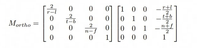
Eigen::Matrix4f get_projection_matrix(float eye_fov, float aspect_ratio, float zNear, float zFar) { // Students will implement this function Eigen::Matrix4f projection = Eigen::Matrix4f::Identity(); Eigen::Matrix4f Mperspective; Mperspective << zNear, 0, 0, 0, 0, zNear, 0, 0, 0, 0, zNear + zFar, -zNear * zFar, 0, 0, 1, 0; /* 假定 eye_fov 是上下的角度 */ /* zNear 需要取反,因为推导的矩阵是建立在 zNear ~ zFar 为负值的情况 */ float half_height = std::tan(eye_fov / 2) * -zNear; float half_width = half_height * aspect_ratio; // 先平移后缩放,正交投影 Eigen::Matrix4f Morth; Morth << 1 / half_width, 0, 0, 0, 0, 1 / half_height, 0, 0, 0, 0, 2 / (zNear - zFar), (zFar - zNear) / (zNear - zFar), 0, 0, 0, 1; projection = Morth * Mperspective; return projection; }
提高项 - 绕任意轴旋转
提高项的内容难在理解推导矩阵公式,推导过程出来之后只需要直接写矩阵公式即可。
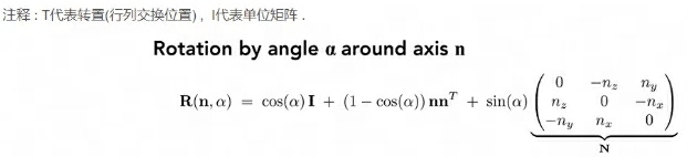
这里主要需要注意:罗德里格斯公式中的矩阵都是 3x3 的,而这里代码中运用了其次坐标,因此返回的格式是 4x4 的矩阵,所以最后还需要转换一下
/* 绕任意轴旋转矩阵 */ Eigen::Matrix4f get_axis_model_matrix(float rotation_angle, Eigen::Vector3f axis) { float angle = rotation_angle / 180 * MY_PI; Eigen::Matrix3f N = Eigen::Matrix3f::Identity(); N << 0, -axis.z(), axis.y(), axis.z(), 0, -axis.x(), -axis.y(), axis.x(), 0; Eigen::Matrix3f rod = std::cos(angle) * Eigen::Matrix3f::Identity() + (1 - std::cos(angle)) * axis * axis.transpose() + std::sin(angle) * N; Eigen::Matrix4f model = Eigen::Matrix4f::Identity(); model << rod(0, 0), rod(0, 1), rod(0, 2), 0, rod(1, 0), rod(1, 1), rod(1, 2), 0, rod(2, 0), rod(2, 1), rod(2, 2), 0, 0, 0, 0, 1; return model; }
作业 2 - 光栅化
要求
在屏幕上画出一个实心三角形,换言之,栅格化一个三角形。
思路
流程其实说的比较清楚了:
- 创建三角形的 2 维 bounding box。
- 遍历此 bounding box 内的所有像素(使用其整数索引)。然后,使用像素中心的屏幕空间坐标来检查中心点是否在三角形内。
- 如果在内部,则将其位置处的插值深度值 (interpolated depth value) 与深度缓冲区 (depth buffer) 中的相应值进行比较。
- 如果当前点更靠近相机,请设置像素颜色并更新深度缓冲区 (depth buffer)。
这里比较麻烦的点在于只知道三角形顶点的深度,需要计算任意点的深度值,需要利用到重心坐标,不过框架中直接提供了这一块的计算公式。因此我们只需要直接利用计算出来的值来比较深度插值即可,该公式具体的推导可以参考
判断点是否位于三角形内
这里对判断是否在三角形内部的接口返回值进行了修改,从 bool 调整为 float,主要是为了适配提高项中的 MSAA 超采样。判断点是否位于三角形内部利用了叉乘的计算方式,给定一个 (x,y) 位置的像素,这里根据超采样的次数 sampleTimes 来决定对一个像素采样多少次。提高项中要求的是 2x2,因此实际采样 4 次。
static bool _insideTriangle(Vector3f P, const Vector3f* _v) { Vector3f AB = _v[1] - _v[0]; Vector3f AP = P - _v[0]; auto cross1 = AB.cross(AP); Vector3f BC = _v[2] - _v[1]; Vector3f BP = P - _v[1]; auto cross2 = BC.cross(BP); Vector3f CA = _v[0] - _v[2]; Vector3f CP = P - _v[2]; auto cross3 = CA.cross(AP); /* 相同符号 */ if ((cross1.z() > 0 && cross2.z() > 0 && cross3.z() > 0) || (cross1.z() < 0 && cross2.z() < 0 && cross3.z() < 0)) { return true; } return false; } /* 采样次数 */ static const int sampleTimes = 1; static const int totalSamplePoint = sampleTimes * sampleTimes; static float insideTriangle(int x, int y, const Vector3f* _v) { // TODO : Implement this function to check if the point (x, y) is inside the triangle represented by _v[0], _v[1], _v[2] Vector3f P = Eigen::Vector3f(x, y, 1.0f); float step = 1.0f / sampleTimes * 0.5f; float lefttopx = P.x() - 0.5; float lefttopy = P.y() + 0.5; float insideTrianglePoints = 0; for (int i = 1; i <= sampleTimes; i++) { for (int j = 1; j <= sampleTimes; j++) { Vector3f SamplePoint = Eigen::Vector3f(lefttopx + i * step, lefttopy - j * step, 1.0f); if (_insideTriangle(SamplePoint, _v)) { insideTrianglePoints += 1; } } } return insideTrianglePoints == 0 ? 0 : insideTrianglePoints / totalSamplePoint; }
光栅化三角形
光栅化三角形的流程比较简单:
- 创建 Bounding Box
- 遍历 Pixel,校验是否在三角形内部
- 计算深度,如果深度更小,说明在更前方,更新深度值并设置颜色
//Screen space rasterization void rst::rasterizer::rasterize_triangle(const Triangle& t) { auto v = t.toVector4(); // TODO : Find out the bounding box of current triangle. // iterate through the pixel and find if the current pixel is inside the triangle float minx = FLT_MAX, maxx = FLT_MIN, miny = FLT_MAX, maxy = FLT_MIN; for (const auto& p : v) { minx = p.x() < minx ? p.x() : minx; maxx = p.x() > maxx ? p.x() : maxx; miny = p.y() < miny ? p.y() : miny; maxy = p.y() > maxy ? p.y() : maxy; } std::cout << "minx=" << minx << " miny=" << miny << " maxx=" << maxx << " maxy=" << maxy << std::endl; // If so, use the following code to get the interpolated z value. for (int y = floor(miny); y < ceil(maxy); y++) { for (int x = floor(minx); x < ceil(maxx); x++) { /* 检查是否在三角形内 */ float samplePercent = insideTriangle(x, y, t.v); if (samplePercent == 0.f) { continue; } /* 重心坐标插值 t.v 是三角形顶点坐标数组*/ auto Barycentric2D = computeBarycentric2D(x, y, t.v); float alpha = std::get<0>(Barycentric2D), beta = std::get<1>(Barycentric2D), gamma = std::get<2>(Barycentric2D); float w_reciprocal = 1.0 / (alpha / v[0].w() + beta / v[1].w() + gamma / v[2].w()); float z_interpolated = alpha * v[0].z() / v[0].w() + beta * v[1].z() / v[1].w() + gamma * v[2].z() / v[2].w(); z_interpolated *= w_reciprocal; // TODO : set the current pixel (use the set_pixel function) to the color of the triangle (use getColor function) if it should be painted. auto ind = get_index(x, y); if (depth_buf[ind] > z_interpolated) { depth_buf[ind] = z_interpolated; Eigen::Vector3f point = Eigen::Vector3f(x, y, 1.0f); set_pixel(point, t.getColor() * samplePercent); } } } }
提高项 - MSAA
这里主要对三角形进行抗锯齿,最终效果如下(感觉不是特别明显,需要放大看)
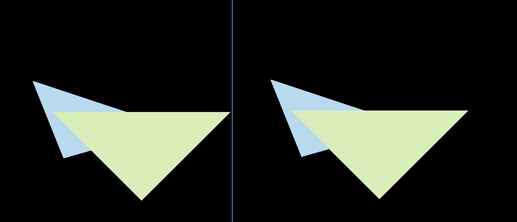
抗锯齿的流程其实在前面实现光栅化的流程中就已经讲述了,但是前面实现的时候少写了一个点,这里每个像素还是采用一个深度值,在两个三角形叠加的边界部分,可能出现一个像素分别被两个三角形占据,而一个深度值会导致最终只显示一个三角形的颜色。因此需要根据对单个三角形 Sample 的次数,增加一个 Sample Depth List(保存每个样本的深度值) 和 Sample Frame List(每个样本的颜色)。最终上色的时候使用样本叠加的颜色。
修改后的光栅化流程如下:
增加 Sample 的 Depth Buffer 和 Frame Buffer
初始化 Buffer
rst::rasterizer::rasterizer(int w, int h) : width(w), height(h) { frame_buf.resize(w * h); depth_buf.resize(w * h); sample_frame_buf.resize(w * h * totalSamplePoint); sample_depth_buf.resize(w * h * totalSamplePoint); }
清理 Buffer
void rst::rasterizer::clear(rst::Buffers buff) { if ((buff & rst::Buffers::Color) == rst::Buffers::Color) { std::fill(frame_buf.begin(), frame_buf.end(), Eigen::Vector3f{0, 0, 0}); } if ((buff & rst::Buffers::Depth) == rst::Buffers::Depth) { std::fill(depth_buf.begin(), depth_buf.end(), std::numeric_limits<float>::infinity()); } if ((buff & rst::Buffers::SampleColor) == rst::Buffers::SampleColor) { std::fill(sample_frame_buf.begin(), sample_frame_buf.end(), Eigen::Vector3f{ 0, 0, 0 }); } if ((buff & rst::Buffers::SampleDepth) == rst::Buffers::SampleDepth) { std::fill(sample_depth_buf.begin(), sample_depth_buf.end(), std::numeric_limits<float>::infinity()); } }
然后在 main 中调用 Clear 的地方加上清理的枚举,需要注意的是这里 Buffers 的枚举是按位或运算,因此不能直接递增,要用 2 的 N 次方
重新调整光栅化
光栅化的调整流程主要是从原来的计算重心坐标只计算像素点,调整为计算采样点。然后更新对应的 Sample Frame Buffer 和 Sample Depth Buffer。最后设置颜色的时候,根据像素的 index,找到对应映射的采样点 Range,求 Color 的 RGB Avg 值即可。
//Screen space rasterization void rst::rasterizer::rasterize_triangle(const Triangle& t) { auto v = t.toVector4(); // TODO : Find out the bounding box of current triangle. // iterate through the pixel and find if the current pixel is inside the triangle float minx = FLT_MAX, maxx = FLT_MIN, miny = FLT_MAX, maxy = FLT_MIN; for (const auto& p : v) { minx = p.x() < minx ? p.x() : minx; maxx = p.x() > maxx ? p.x() : maxx; miny = p.y() < miny ? p.y() : miny; maxy = p.y() > maxy ? p.y() : maxy; } std::cout << "minx=" << minx << " miny=" << miny << " maxx=" << maxx << " maxy=" << maxy << std::endl; // If so, use the following code to get the interpolated z value. for (int x = floor(minx); x < ceil(maxx); x++) { for (int y = floor(miny); y < ceil(maxy); y++) { /* 检查是否在三角形内 */ float grid_width = 1.0f / sampleTimes; float grid_p_offset = grid_width * 0.5f; // 左上角开始算 float lefttopx = x - 0.5f; float lefttopy = y - 0.5f; bool should_set_color = false; for (int i = 0; i < sampleTimes; i++) { for (int j = 0; j < sampleTimes; j++) { float samplex = lefttopx + i * grid_width + grid_p_offset; float sampley = lefttopy + j * grid_width + grid_p_offset; if (insideTriangle(samplex, sampley, t.v)) { // 计算重心坐标 auto Barycentric2D = computeBarycentric2D(samplex, sampley, t.v); float alpha = std::get<0>(Barycentric2D), beta = std::get<1>(Barycentric2D), gamma = std::get<2>(Barycentric2D); float w_reciprocal = 1.0 / (alpha / v[0].w() + beta / v[1].w() + gamma / v[2].w()); float z_interpolated = alpha * v[0].z() / v[0].w() + beta * v[1].z() / v[1].w() + gamma * v[2].z() / v[2].w(); z_interpolated *= w_reciprocal; int sample_ind = get_index(x, y) + i * sampleTimes + j; float sample_z = sample_depth_buf[sample_ind]; if (sample_z > z_interpolated) { should_set_color = true; sample_depth_buf[sample_ind] = z_interpolated; sample_frame_buf[sample_ind] = t.getColor() / totalSamplePoint; } } } } int ind = get_index(x, y); Vector3f final_color = { 0, 0, 0 }; for (int i = ind; i < ind + totalSamplePoint; i++) { final_color += sample_frame_buf[i]; } Eigen::Vector3f point = Eigen::Vector3f(x, y, 1.0f); set_pixel(point, final_color); } } }
作业 3 - Shading
要求
- 修改函数 rasterize_triangle(const Triangle& t) in rasterizer.cpp: 在此处实现与作业 2 类似的插值算法,实现法向量、颜色、纹理颜色的插值。
- 修改函数 get_projection_matrix() in main.cpp: 将你自己在之前的实验中实现的投影矩阵填到此处,此时你可以运行 ./Rasterizer output.png normal 来观察法向量实现结果。
- 修改函数 phong_fragment_shader() in main.cpp: 实现 Blinn-Phong 模型计算 Fragment Color.
- 修改函数 texture_fragment_shader() in main.cpp: 在实现 Blinn-Phong 的基础上,将纹理颜色视为公式中的 kd,实现 Texture Shading Fragment Shader.
- 修改函数 bump_fragment_shader() in main.cpp: 在实现 Blinn-Phong 的基础上,仔细阅读该函数中的注释,实现 Bump mapping.
- 修改函数 displacement_fragment_shader() in main.cpp: 在实现 Bumpmapping 的基础上,实现 displacement mapping
作业的一些问题
摘自论坛作业三公告
(1) bump mapping 部分的 h(u,v)=texture_color(u,v).norm, 其中 u,v 是 tex_coords, w,h 是 texture 的宽度与高度
(2) rasterizer.cpp 中 v = t.toVector4()
(3) get_projection_matrix 中的 eye_fov 应该被转化为弧度制
(4) bump 与 displacement 中修改后的 normal 仍需要 normalize
(5) 可能用到的 eigen 方法:norm(), normalized(), cwiseProduct()
(6) 实现 h(u+1/w,v) 的时候要写成 h(u+1.0/w,v)
(7) 正规的凹凸纹理应该是只有一维参量的灰度图,而本课程为了框架使用的简便性而使用了一张 RGB 图作为凹凸纹理的贴图,因此需要指定一种规则将彩色投影到灰度,而我只是「恰好」选择了 norm 而已。为了确保你们的结果与我一致,我才要求你们都使用 norm 作为计算方法。
(8) bump mapping & displacement mapping 的计算的推导日后将会在光线追踪部分详细介绍,目前请按照注释实现。
思路
总体的思路是先做好光栅化,对三角形的各个属性在面上的点做插值,其次就是做 shader,应用不同的光照模型 or 贴图。
光栅化
第一步的首先需要做光栅化,这里主要应用到重心坐标的概念。对属性进行插值的方式和作业二类似。这里需要注意的是有个 interpolated_shadingcoords ,这里其实是从 eye pos 出发打到三角形的各个顶点插值后的坐标。也就是三角形的被观测点。
//Screen space rasterization void rst::rasterizer::rasterize_triangle(const Triangle& t, const std::array<Eigen::Vector3f, 3>& view_pos) { const auto& v = t.toVector4(); const auto& color = t.color; const auto& normal = t.normal; const auto& texcoord = t.tex_coords; float xmin = FLT_MAX, xmax = FLT_MIN, ymin = FLT_MAX, ymax = FLT_MIN; for (const auto& p : v) { xmin = p.x() < xmin ? p.x() : xmin; xmax = p.x() > xmax ? p.x() : xmax; ymin = p.y() < ymin ? p.y() : ymin; ymax = p.y() > ymax ? p.y() : ymax; } // If so, use the following code to get the interpolated z value. for (int y = floor(ymin); y < ceil(ymax); y++) { for (int x = floor(xmin); x < ceil(xmax); x++) { /* 检查是否在三角形内 */ if (!insideTriangle(x, y, t.v)) { continue; } /* 重心坐标插值 t.v 是三角形顶点坐标数组*/ auto [alpha, beta, gamma] = computeBarycentric2D(x, y, t.v); float w_reciprocal = 1.0 / (alpha / v[0].w() + beta / v[1].w() + gamma / v[2].w()); /* Z 插值 */ float z_interpolated = alpha * v[0].z() / v[0].w() + beta * v[1].z() / v[1].w() + gamma * v[2].z() / v[2].w(); z_interpolated *= w_reciprocal; // TODO : set the current pixel (use the set_pixel function) to the color of the triangle (use getColor function) if it should be painted. auto ind = get_index(x, y); if (depth_buf[ind] > z_interpolated) { depth_buf[ind] = z_interpolated; // * 颜色插值 * Vector3f interpolated_color = alpha * color[0] + beta * color[1] + gamma * color[2] ; interpolated_color *= w_reciprocal; // * 法线插值 * Vector3f interpolated_normal = alpha * normal[0] + beta * normal[1] + gamma * normal[2] ; interpolated_normal *= w_reciprocal; // * 纹理插值 * Vector2f interpolated_texcoords = alpha * texcoord[0] + beta * texcoord[1] + gamma * texcoord[2] ; interpolated_texcoords *= w_reciprocal; // * 观测点插值 * Vector3f interpolated_shadingcoords = alpha * view_pos[0] + beta * view_pos[1] + gamma * view_pos[2]; interpolated_shadingcoords *= w_reciprocal; fragment_shader_payload payload( interpolated_color, interpolated_normal.normalized(), interpolated_texcoords, texture ? &*texture : nullptr); payload.view_pos = interpolated_shadingcoords; // Use: Instead of passing the triangle's color directly to the frame buffer, pass the color to the shaders first to get the final color; auto pixel_color = fragment_shader(payload); Eigen::Vector2i point = Eigen::Vector2i(x, y); set_pixel(point, pixel_color); } } } }
normal_fragment_shader
框架默认实现了该 Shader,处理完默认的光栅化后即可看到效果
phong_fragment_shader
接下来需要实现光照的 Phong 模型,简单套公式即可
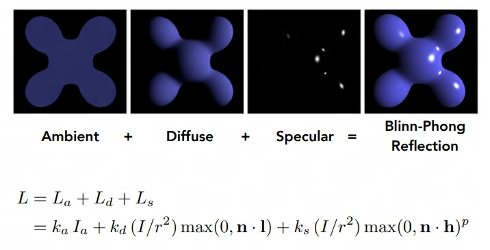
其中有几点需要注意:
- 表示 光照的 Intensity
- Vector3f 相乘需要使用 cwiseProduct
- 计算半程向量,法线等向量时需要进行归一化
Eigen::Vector3f phong_fragment_shader(const fragment_shader_payload& payload) { Eigen::Vector3f ka = Eigen::Vector3f(0.005, 0.005, 0.005); Eigen::Vector3f kd = payload.color; Eigen::Vector3f ks = Eigen::Vector3f(0.7937, 0.7937, 0.7937); auto l1 = light{{20, 20, 20}, {500, 500, 500}}; auto l2 = light{{-20, 20, 0}, {500, 500, 500}}; std::vector<light> lights = {l1, l2}; Eigen::Vector3f amb_light_intensity{10, 10, 10}; Eigen::Vector3f eye_pos{0, 0, 10}; float p = 150; Eigen::Vector3f color = payload.color; Eigen::Vector3f point = payload.view_pos; Eigen::Vector3f normal = payload.normal; Eigen::Vector3f result_color = {0, 0, 0}; for (auto& light : lights) { // TODO: For each light source in the code, calculate what the *ambient*, *diffuse*, and *specular* // components are. Then, accumulate that result on the *result_color* object. Vector3f l = (light.position - point); Vector3f v = eye_pos - point; float r_square = l.dot(l); // 计算 ambient 环境光 Vector3f ambient = ka.cwiseProduct(amb_light_intensity); // 计算 diffuse 漫反射光 float ndotl = normal.normalized().dot(l.normalized()); Vector3f diffuse = kd.cwiseProduct(light.intensity / r_square * std::max(0.f, ndotl)); // 计算 specular 高光 Vector3f h = l.normalized() + v.normalized(); float ndoth = normal.normalized().dot(h.normalized()); Vector3f specular = ks.cwiseProduct(light.intensity / r_square) * pow(std::max(0.f, ndoth), p); result_color += (ambient + diffuse + specular); } return result_color * 255.f; }
texture_fragment_shader
这里主要将物体表面的颜色替换成 Texture 的 getColor 接口,需要注意的是:(u,v) 坐标在实际应用中可能存在负数或者 > 1(正常取值范围在 0 ~ 1),所以还需要做有效性检测
Eigen::Vector3f texture_fragment_shader(const fragment_shader_payload& payload) { Eigen::Vector3f return_color = {0, 0, 0}; Eigen::Vector3f texture_color; if (payload.texture) { // TODO: Get the texture value at the texture coordinates of the current fragment /* 获取纹理坐标 */ float x = payload.tex_coords.x(); float y = payload.tex_coords.y(); if (x < 0 || x > 1 || y < 0 || y > 1) { std::cout << "error tex coords x=" << x << " y=" << y << std::endl; texture_color << return_color.x(), return_color.y(), return_color.z(); } else { texture_color = payload.texture->getColor(x, y); } } //texture_color << return_color.x(), return_color.y(), return_color.z(); Eigen::Vector3f ka = Eigen::Vector3f(0.005, 0.005, 0.005); Eigen::Vector3f kd = texture_color / 255.f; Eigen::Vector3f ks = Eigen::Vector3f(0.7937, 0.7937, 0.7937); auto l1 = light{{20, 20, 20}, {500, 500, 500}}; auto l2 = light{{-20, 20, 0}, {500, 500, 500}}; std::vector<light> lights = {l1, l2}; Eigen::Vector3f amb_light_intensity{10, 10, 10}; Eigen::Vector3f eye_pos{0, 0, 10}; float p = 150; Eigen::Vector3f color = texture_color; Eigen::Vector3f point = payload.view_pos; Eigen::Vector3f normal = payload.normal; Eigen::Vector3f result_color = {0, 0, 0}; for (auto& light : lights) { // TODO: For each light source in the code, calculate what the *ambient*, *diffuse*, and *specular* // components are. Then, accumulate that result on the *result_color* object. Vector3f l = (light.position - point); Vector3f v = eye_pos - point; float r_square = l.dot(l); // 计算 ambient 环境光 Vector3f ambient = ka.cwiseProduct(amb_light_intensity); // 计算 diffuse 漫反射光 float ndotl = normal.normalized().dot(l.normalized()); Vector3f diffuse = kd.cwiseProduct(light.intensity / r_square * std::max(0.f, ndotl)); // 计算 specular 高光 Vector3f h = l.normalized() + v.normalized(); float ndoth = normal.normalized().dot(h.normalized()); Vector3f specular = ks.cwiseProduct(light.intensity / r_square) * pow(std::max(0.f, ndoth), p); result_color += (ambient + diffuse + specular); } return result_color * 255.f; }
bump_fragment_shader
这一节主要实现凹凸贴图。这里有个严重的问题是注释中的 h(u,v) 计算完全没有提及,后续作业三的公告中才做了解释:bump mapping 部分的 h(u,v)=texture_color(u,v).norm, 其中 u,v 是 tex_coords, w,h 是 texture 的宽度与高度 。
这里的核心思路是扰动法线,利用贴图的法线信息和原本物体表面的法线来计算出扰动后的法线,用到了 TBN 矩阵和切线空间,这两个知识点需要后续补齐。
Eigen::Vector3f bump_fragment_shader(const fragment_shader_payload& payload) { Eigen::Vector3f ka = Eigen::Vector3f(0.005, 0.005, 0.005); Eigen::Vector3f kd = payload.color; Eigen::Vector3f ks = Eigen::Vector3f(0.7937, 0.7937, 0.7937); auto l1 = light{{20, 20, 20}, {500, 500, 500}}; auto l2 = light{{-20, 20, 0}, {500, 500, 500}}; std::vector<light> lights = {l1, l2}; Eigen::Vector3f amb_light_intensity{10, 10, 10}; Eigen::Vector3f eye_pos{0, 0, 10}; float p = 150; Eigen::Vector3f color = payload.color; Eigen::Vector3f point = payload.view_pos; Eigen::Vector3f normal = payload.normal; float kh = 0.2, kn = 0.1; // TODO: Implement bump mapping here // Let n = normal = (x, y, z) // Vector t = (x*y/sqrt(x*x+z*z),sqrt(x*x+z*z),z*y/sqrt(x*x+z*z)) // Vector b = n cross product t // Matrix TBN = [t b n] // dU = kh * kn * (h(u+1/w,v)-h(u,v)) // dV = kh * kn * (h(u,v+1/h)-h(u,v)) // Vector ln = (-dU, -dV, 1) // Normal n = normalize(TBN * ln) // TODO: Implement displacement mapping here float x = normal.x(), y = normal.y(), z = normal.z(); Vector3f t = Eigen::Vector3f(x * y / sqrt(x * x + z * z), sqrt(x * x + z * z), z * y / sqrt(x * x + z * z)); Vector3f b = normal.cross(t); float h = payload.texture->height; float w = payload.texture->width; float u = payload.tex_coords.x(); float v = payload.tex_coords.y(); Eigen::Matrix3f TBN; TBN << t.x(), b.x(), normal.x(), t.y(), b.y(), normal.y(), t.z(), b.z(), normal.z(); float dU = 0, dV = 0; if (payload.texture && is_valid_uv(u, v)) { dU = kh * kn * (payload.texture->getColor(u + 1.0f / w, v).norm() - payload.texture->getColor(u, v).norm()); dV = kh * kn * (payload.texture->getColor(u, v + 1.0f / h).norm() - payload.texture->getColor(u, v).norm()); } Vector3f ln = Eigen::Vector3f(-dU, -dV, 1); normal = (TBN * ln); Eigen::Vector3f result_color = { 0, 0, 0 }; result_color = normal; return result_color * 255.f; }
displacement_fragment_shader
这里的流程和 Bump Shader 基本一致,主要的区别在于,Bump Fragment Shader 只做法线扰动,而 Displacement Fragment Shader 会修改三角面上的顶点值。
Eigen::Vector3f displacement_fragment_shader(const fragment_shader_payload& payload) { Eigen::Vector3f ka = Eigen::Vector3f(0.005, 0.005, 0.005); Eigen::Vector3f kd = payload.color; Eigen::Vector3f ks = Eigen::Vector3f(0.7937, 0.7937, 0.7937); auto l1 = light{{20, 20, 20}, {500, 500, 500}}; auto l2 = light{{-20, 20, 0}, {500, 500, 500}}; std::vector<light> lights = {l1, l2}; Eigen::Vector3f amb_light_intensity{10, 10, 10}; Eigen::Vector3f eye_pos{0, 0, 10}; float p = 150; Eigen::Vector3f color = payload.color; Eigen::Vector3f point = payload.view_pos; Eigen::Vector3f normal = payload.normal; float kh = 0.2, kn = 0.1; // TODO: Implement displacement mapping here float x = normal.x(), y = normal.y(), z = normal.z(); Vector3f t = Eigen::Vector3f(x * y / sqrt(x * x + z * z), sqrt(x * x + z * z), z * y / sqrt(x * x + z * z)); Vector3f b = normal.cross(t); float h = payload.texture->height; float w = payload.texture->width; float u = payload.tex_coords.x(); float v = payload.tex_coords.y(); Eigen::Matrix3f TBN; TBN << t.x(), b.x(), normal.x(), t.y(), b.y(), normal.y(), t.z(), b.z(), normal.z(); float dU = 0, dV = 0; if (payload.texture && is_valid_uv(u, v)) { dU = kh * kn * (payload.texture->getColor(u + 1.0f / w, v).norm() - payload.texture->getColor(u, v).norm()); dV = kh * kn * (payload.texture->getColor(u, v + 1.0f / h).norm() - payload.texture->getColor(u, v).norm()); point += kn * normal * (payload.texture->getColor(u, v).norm()); } Vector3f ln = Eigen::Vector3f(-dU, -dV, 1); normal = (TBN * ln); Eigen::Vector3f result_color = {0, 0, 0}; for (auto& light : lights) { // TODO: For each light source in the code, calculate what the *ambient*, *diffuse*, and *specular* // components are. Then, accumulate that result on the *result_color* object. Vector3f l = (light.position - point); Vector3f v = eye_pos - point; float r_square = l.dot(l); // 计算 ambient 环境光 Vector3f ambient = ka.cwiseProduct(amb_light_intensity); // 计算 diffuse 漫反射光 float ndotl = normal.normalized().dot(l.normalized()); Vector3f diffuse = kd.cwiseProduct(light.intensity / r_square * std::max(0.f, ndotl)); // 计算 specular 高光 Vector3f h = l.normalized() + v.normalized(); float ndoth = normal.normalized().dot(h.normalized()); Vector3f specular = ks.cwiseProduct(light.intensity / r_square) * pow(std::max(0.f, ndoth), p); result_color += (ambient + diffuse + specular); } return result_color * 255.f; }
提高项 - 双线性纹理采样
这里主要是针对纹理过大,多个像素使用同个纹素的问题,双线性纹理采样后可以让被放大的纹理更加平滑,做法如下:
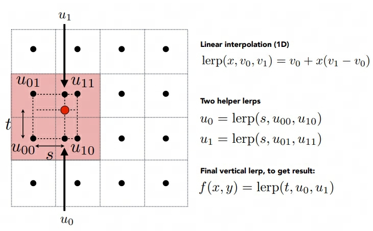
简单做插值即可。
Eigen::Vector3f getColorBilinear(float u, float v) { auto u_img = u * width; auto v_img = (1 - v) * height; float u11 = ceil(u_img); float v11 = ceil(v_img); float u01 = floor(u_img); float v01 = floor(v_img); auto color1 = image_data.at<cv::Vec3b>(v01, u11); auto color2 = image_data.at<cv::Vec3b>(v01, u01); auto color3 = image_data.at<cv::Vec3b>(v11, u11); auto color4 = image_data.at<cv::Vec3b>(v11, u01); float s = (u_img - u01) / (u11 - u01); float t = (v_img - v01) / (v11 - v01); auto color5 = color4 + s * (color3 - color4); auto color6 = color2 + s * (color1 - color2); auto final_color = color6 + t * (color5 - color6); return Eigen::Vector3f(final_color[0], final_color[1], final_color[2]); }
作业 4 - 贝塞尔曲线
要求
Bézier 曲线是一种用于计算机图形学的参数曲线。在本次作业中,你需要实现 de Casteljau 算法来绘制由 4 个控制点表示的 Bézier 曲线 (当你正确实现该算法时,你可以支持绘制由更多点来控制的 Bézier 曲线)。
你需要修改的函数在提供的 main.cpp 文件中。
• bezier:该函数实现绘制 Bézier 曲线的功能。它使用一个控制点序列和一个 OpenCV::Mat 对象作为输入,没有返回值。它会使 t 在 0 到 1 的范围内进行迭代,并在每次迭代中使 t 增加一个微小值。对于每个需要计算的 t,将调用另一个函数 recursive_bezier,然后该函数将返回在 Bézier 曲线上 t 处的点。最后,将返回的点绘制 OpenCV ::Mat 对象上。
• recursive_bezier:该函数使用一个控制点序列和一个浮点数 t 作为输入,实现 de Casteljau 算法来返回 Bézier 曲线上对应点的坐标
思路
总体比较简单,利用课程上讲述的递归算法实现即可
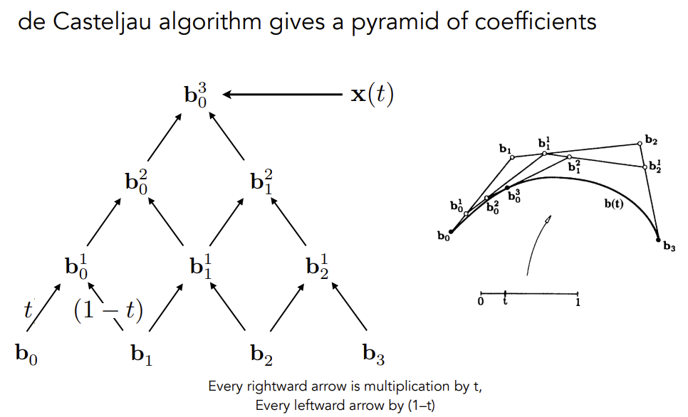
利用给定的控制点,递归计算可以得到下一组控制点,直到控制点的数量为 1 ,即可返回。
cv::Point2f recursive_bezier(const std::vector<cv::Point2f>& control_points, float t) { // TODO: Implement de Casteljau's algorithm if (control_points.size() == 1) { return control_points[0]; } std::vector<cv::Point2f> new_control_points; for (int i = 0; i < control_points.size() - 1; i++) { new_control_points.push_back(control_points[i] * t + control_points[i + 1] * (1 - t)); } return recursive_bezier(new_control_points, t); } void bezier(const std::vector<cv::Point2f>& control_points, cv::Mat& window) { // TODO: Iterate through all t = 0 to t = 1 with small steps, and call de Casteljau's // recursive Bezier algorithm. for (double t = 0.0; t <= 1.0; t += 0.001) { auto point = recursive_bezier(control_points, t); window.at<cv::Vec3b>(point.y, point.x)[1] = 255; } }
提高项
要求对曲线做抗锯齿,原先的曲线长这样
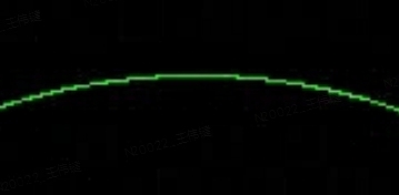
要求中提示可以直接根据距离做着色,一开始选择用返回的控制点周围的 2x2 像素,发现效果不是很好,最终选择 3x3,控制点的 x,y 坐标进行 round 操作取到九宫格中心点,控制点离像素点的最远距离为 1.5 * ,因为最远的情况可能为左上角的像素中心点到控制点像素的右下角,一个像素的对角线长度为 ,所以是 。所以要做的就是遍历 9 个像素,取到每个像素的中心点与控制点的距离,然后投影到 255 ~ 0 的 RGB 区间。
cv::Point2f recursive_bezier(const std::vector<cv::Point2f>& control_points, float t) { // TODO: Implement de Casteljau's algorithm if (control_points.size() == 1) { return control_points[0]; } std::vector<cv::Point2f> new_control_points; for (int i = 0; i < control_points.size() - 1; i++) { new_control_points.push_back(control_points[i] * t + control_points[i + 1] * (1 - t)); } return recursive_bezier(new_control_points, t); } void bezier(const std::vector<cv::Point2f>& control_points, cv::Mat& window) { // TODO: Iterate through all t = 0 to t = 1 with small steps, and call de Casteljau's // recursive Bezier algorithm. float max_dist = 1.5f * sqrt(2); for (double t = 0.0; t <= 1.0; t += 0.001) { auto point = recursive_bezier(control_points, t); for (int i = round(point.x) - 1; i < round(point.x) + 2; i++) { for (int j = round(point.y) - 1; j < round(point.y) + 2; j++) { auto sample_point = cv::Point2f(i, j); float d = cv::norm(sample_point - point); std::cout << d << std::endl; float rgb = (1.0f - (d / max_dist)) * 255.0f; float old_rgb = window.at<cv::Vec3b>(sample_point.y, sample_point.x)[1]; window.at<cv::Vec3b>(sample_point.y, sample_point.x)[1] = old_rgb < rgb ? rgb : old_rgb; } } } }
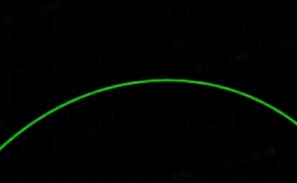
修改后的效果如下;
作业 5 - 光线与三角形相交
要求
在这部分的课程中,我们将专注于使用光线追踪来渲染图像。在光线追踪中最重要的操作之一就是找到光线与物体的交点。一旦找到光线与物体的交点,就可以执行着色并返回像素颜色。在这次作业中,我们需要实现两个部分:光线的生成和光线与三角的相交。本次代码框架的工作流程为:
- 从 main 函数开始。我们定义场景的参数,添加物体(球体或三角形)到场景中,并设置其材质,然后将光源添加到场景中。
- 调用 Render (scene) 函数。在遍历所有像素的循环里,生成对应的光线并将返回的颜色保存在帧缓冲区(framebuffer)中。在渲染过程结束后,帧缓冲区中的信息将被保存为图像。
- 在生成像素对应的光线后,我们调用 CastRay 函数,该函数调用 trace 来查询光线与场景中最近的对象的交点。
- 然后,我们在此交点执行着色。我们设置了三种不同的着色情况,并且已经为你提供了代码。
你需要修改的函数是:
• Renderer. Cpp 中的 Render ():这里你需要为每个像素生成一条对应的光线,然后调用函数 castRay () 来得到颜色,最后将颜色存储在帧缓冲区的相应像素中。
• Triangle. Hpp 中的 rayTriangleIntersect (): v 0, v 1, v 2 是三角形的三个顶点,orig 是光线的起点,dir 是光线单位化的方向向量。Tnear, u, v 是你需要使用我们课上推导的 Moller-Trumbore 算法来更新的参数。
思路
实现主要分两步:
- 对每个像素打射线
- 检查射线和三角形是否相交
对每个像素生成射线
课程中没有讲述具体的过程,这里主要参考如下:
- 生成相机光线: 栅格空间-NDC-屏幕空间-世界空间
- Ray-Tracing: Generating Camera Rays
简单来说,我们需要把屏幕坐标转换成世界坐标,然后我们有两个信息点: - 相机位于世界坐标系原点
- 成像平面离世界坐标系原点只有 zNear 单位的距离,并沿负 z 轴对齐
简而言之,如果我们的屏幕分辨率为 1024 x 768,那么我们需要将这个坐标先归一化,然后再转换到 (-1,1)的空间。
void Renderer::Render(const Scene& scene) { /*省略代码*/ std::vector<Vector3f> framebuffer(scene.width * scene.height); float scale = std::tan(deg2rad(scene.fov * 0.5f)); float imageAspectRatio = scene.width / (float)scene.height; // Use this variable as the eye position to start your rays. float pixel_width = 1.0f; float offset = pixel_width * 0.5f; for (int j = 0; j < scene.height; ++j) { for (int i = 0; i < scene.width; ++i) { // 先归一化到 (0, 1) auto norm_x = ((i * pixel_width) + offset) / scene.width; auto norm_y = ((j * pixel_width) + offset) / scene.height; // 转换到 (-1 , 1) norm_x = norm_x * 2 - 1; norm_y = norm_y * 2 - 1; // scale 表示 near 平面拖远之后,成像平面应该缩放的倍数 // imageAspectRatio 表示宽高比,因为不一定是 1:1 ,而前面归一化成为了正方形 float x = norm_x * scale * imageAspectRatio; // 最终需要 * -1,因为光栅化空间坐标是从左上角为 (0,0),正常是左下角为 (0,0),需要翻转下 y 轴 float y = norm_y * scale * -1; // TODO: Find the x and y positions of the current pixel to get the direction // vector that passes through it. // Also, don't forget to multiply both of them with the variable *scale*, and // x (horizontal) variable with the *imageAspectRatio* Vector3f dir = Vector3f(x, y, -1); // Don't forget to normalize this direction! framebuffer[m++] = castRay(eye_pos, normalize(dir), scene, 0); } UpdateProgress(j / (float)scene.height); } /*省略代码*/ }
判断三角形与射线是否相交
这里直接代入公式即可:
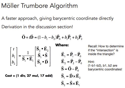
和 分别表示 u 和 v,也就是三角形的重心坐标。
bool rayTriangleIntersect(const Vector3f& v0, const Vector3f& v1, const Vector3f& v2, const Vector3f& orig, const Vector3f& dir, float& tnear, float& u, float& v) { // TODO: Implement this function that tests whether the triangle // that's specified bt v0, v1 and v2 intersects with the ray (whose // origin is *orig* and direction is *dir*) // Also don't forget to update tnear, u and v. auto e1 = v1 - v0, e2 = v2 - v0, s = orig - v0; auto s1 = crossProduct(dir, e2), s2 = crossProduct(s, e1); float t = dotProduct(s2, e2) / dotProduct(s1, e1); float b1 = dotProduct(s1, s) / dotProduct(s1, e1); float b2 = dotProduct(s2, dir) / dotProduct(s1, e1); if (t > 0.0 && b1 >= 0.0 && b2 >= 0.0 && (1 - b1 - b2) >= 0.0) { tnear = t; u = b1; v = b2; return true; } return false; }
作业 6 - BVH 加速
要求
首先,你需要从上一次编程练习中引用以下函数:
• Render() in Renderer.cpp: 将你的光线生成过程粘贴到此处,并且按照新框架更新相应调用的格式。
• Triangle::getIntersection in Triangle.hpp: 将你的光线-三角形相交函数粘贴到此处,并且按照新框架更新相应相交信息的格式。在本次编程练习中,你需要实现以下函数:
• IntersectP(const Ray& ray, const Vector3f& invDir, const std::array<int, 3>& dirIsNeg) in the Bounds3.hpp: 这个函数的作用是判断包围盒 BoundingBox 与光线是否相交,你需要按照课程介绍的算法实现求交过程。
• getIntersection(BVHBuildNode* node, const Ray ray) in BVH.cpp: 建立 BVH 之后,我们可以用它加速求交过程。该过程递归进行,你将在其中调用你实现的 Bounds3::IntersectP
思路
前两点对 Render 和 Triangle 的修改比较简单,不多赘述(感觉没有必要多此一举让我们再补充这些代码),重点在于后面两点:
光线与 AABB 判断相交
AABB 包围盒由 6 个平面构成,将其延申,分为 3 组平面,分别对应 x,y,z 三根坐标轴,然后依次求出每个平面打到光线时的 t 值。
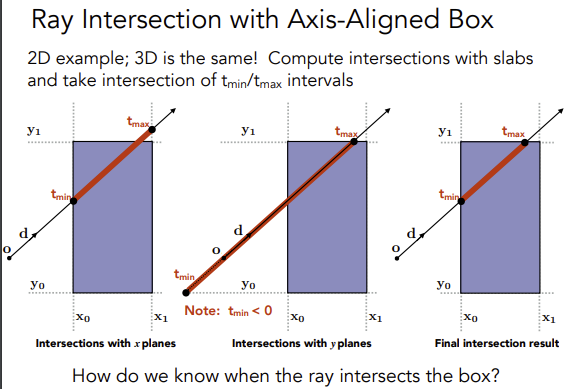
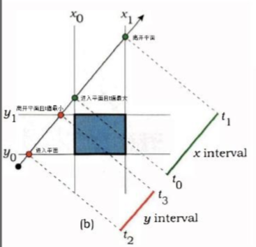
我们计算 中,t 的值表示光线经过多久会打到 AABB,以 x 轴为例,进入 x 轴平面的计算为 ,其中只有 t 未知,解的 t 之后得到进入 x 轴平面的时间,然后依次计算得到其他轴的 t,最后比较得到最晚进入的时间。离开包围盒的时间也是同理,最后计算出最早离开包围盒的时间。思考下图:
代码如下,其中 invDir 的用意是可以直接拿来做乘法,效率更高,而 dirIsNeg 表示光线的方向,如果在往负方向则比较值的方向也需要取反。
inline bool Bounds3::IntersectP(const Ray& ray, const Vector3f& invDir, const std::array<int, 3>& dirIsNeg) const { // invDir: ray direction(x,y,z), invDir=(1.0/x,1.0/y,1.0/z), use this because Multiply is faster that Division // dirIsNeg: ray direction(x,y,z), dirIsNeg=[int(x>0),int(y>0),int(z>0)], use this to simplify your logic // TODO test if ray bound intersects float t_x_min = (pMin.x - ray.origin.x) * invDir.x; float t_y_min = (pMin.y - ray.origin.y) * invDir.y; float t_z_min = (pMin.z - ray.origin.z) * invDir.z; float t_x_max = (pMax.x - ray.origin.x) * invDir.x; float t_y_max = (pMax.y - ray.origin.y) * invDir.y; float t_z_max = (pMax.z - ray.origin.z) * invDir.z; if (!dirIsNeg[0]) { std::swap(t_x_min, t_x_max); } if (!dirIsNeg[1]) { std::swap(t_y_min, t_y_max); } if (!dirIsNeg[2]) { std::swap(t_z_min, t_z_max); } float t_enter = std::max(std::max(t_x_min, t_y_min), t_z_min); float t_exit = std::min(std::min(t_x_max, t_y_max), t_z_max); if (t_enter < t_exit && t_exit >= 0) return true; else return false; }
BVH 查询
这个比较简单,按照课程上的算法来即可:
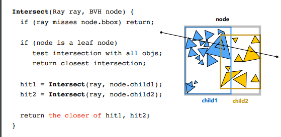
Intersection BVHAccel::getIntersection(BVHBuildNode* node, const Ray& ray) const { // TODO Traverse the BVH to find intersection const std::array<int, 3> dirIsNeg = { int(ray.direction.x > 0), int(ray.direction.y > 0), int(ray.direction.z > 0) }; if (!node->bounds.IntersectP(ray, ray.direction_inv, dirIsNeg)) { return {}; } if (node->object) { return node->object->getIntersection(ray); } /* 深度优先 */ auto leftIntersection = getIntersection(node->left, ray); auto rightIntersction = getIntersection(node->right, ray); /* 取最近打到的物体 可能出现: 1. 1 个打到 1 个没打到 2. 两个全命中了物体,检查命中较近的物体 */ return leftIntersection.distance >= rightIntersction.distance ? rightIntersction : leftIntersection; }
提高项 - SAH
SAH 的介绍 ,原本 BVH 是直接取空间包围盒最长的轴,对物体按距离排序做二分,而 SAH 主要是基于面积公式和概率论的方式来计算包围盒。这里使用分桶的方法:
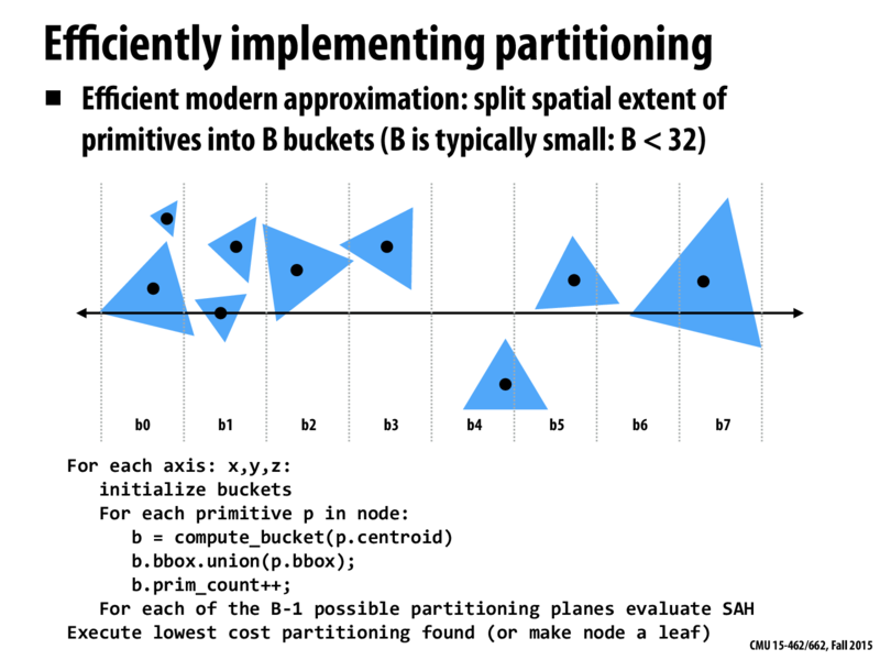
代码段会对每个轴 (x, y, z) 进行操作。
- 对于每个轴,首先初始化一个桶(bucket):创建一个大小为B的桶数组。B通常比较小,例如小于32。
- 然后计算每一个物体p的质心(centroid),看看这个物体落在哪个桶里。
- 将物体p的包围盒与桶b的包围盒做并集操作,也就是扩展桶b的包围盒,使其能够包含物体p。
- 增加桶b中的物体计数。
- 对于每个可能的划分平面(总共有B-1个),使用表面积启发式(SAH)公式评估其成本。
- 执行成本最低的划分(如果找不到有效的划分,就将当前节点设为叶子节点)。
原本需要对所有物体的每一种可能划分进行评估,现在只需要对B-1个划分进行评估。因此,分桶方法可以在构建BVH时,有效地降低计算复杂度,提高算法的效率。
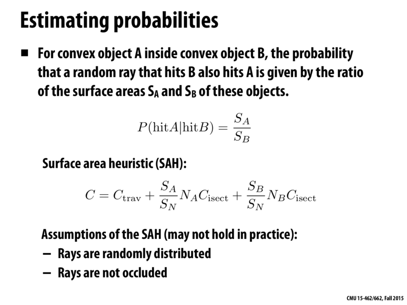
划分策略:SAH的目标是找到一种空间划分方式,使得整体花费最小。
假设有 A 个物体被划分到 x 子节点,B 个物体被划分到 y 子节点,且假设穿过子节点的概率 p 与该节点的包围盒大小成正比。那么,空间划分的总花费 C 可以近似为上图中的公式。
其中, 、 分别表示x、y子节点的表面积, 表示整个节点的表面积, 、 分别表示 x、y 子节点中的物体数量, 表示射线与物体相交的计算成本。
BVHBuildNode* BVHAccel::recursiveBuild(std::vector<Object*> objects) { BVHBuildNode* node = new BVHBuildNode(); // Compute bounds of all primitives in BVH node Bounds3 bounds; for (int i = 0; i < objects.size(); ++i) bounds = Union(bounds, objects[i]->getBounds()); if (objects.size() == 1) { // Create leaf _BVHBuildNode_ node->bounds = objects[0]->getBounds(); node->object = objects[0]; node->left = nullptr; node->right = nullptr; return node; } else if (objects.size() == 2) { node->left = recursiveBuild(std::vector{objects[0]}); node->right = recursiveBuild(std::vector{objects[1]}); node->bounds = Union(node->left->bounds, node->right->bounds); return node; } else { Bounds3 centroidBounds; for (int i = 0; i < objects.size(); ++i) centroidBounds = Union(centroidBounds, objects[i]->getBounds().Centroid()); int dim = centroidBounds.maxExtent(); switch (dim) { case 0: std::sort(objects.begin(), objects.end(), [](auto f1, auto f2) { return f1->getBounds().Centroid().x < f2->getBounds().Centroid().x; }); break; case 1: std::sort(objects.begin(), objects.end(), [](auto f1, auto f2) { return f1->getBounds().Centroid().y < f2->getBounds().Centroid().y; }); break; case 2: std::sort(objects.begin(), objects.end(), [](auto f1, auto f2) { return f1->getBounds().Centroid().z < f2->getBounds().Centroid().z; }); break; } switch (SplitMethod::SAH) { case SplitMethod::NAIVE: { auto beginning = objects.begin(); auto middling = objects.begin() + (objects.size() / 2); auto ending = objects.end(); auto leftshapes = std::vector<Object*>(beginning, middling); auto rightshapes = std::vector<Object*>(middling, ending); assert(objects.size() == (leftshapes.size() + rightshapes.size())); node->left = recursiveBuild(leftshapes); node->right = recursiveBuild(rightshapes); node->bounds = Union(node->left->bounds, node->right->bounds); break; } case SplitMethod::SAH: { // 定义 10 个桶 float min_cost = std::numeric_limits<float>::infinity(); const int buckets = 10; int suitable_bucket_index = 1; for (int i = 1; i <= buckets; i++) { auto beginning = objects.begin(); auto middling = objects.begin() + (objects.size() * i / buckets); auto ending = objects.end(); auto leftshapes = std::vector<Object*>(beginning, middling); auto rightshapes = std::vector<Object*>(middling, ending); Bounds3 leftbounds, rightbounds; for (auto object : leftshapes) { leftbounds = Union(leftbounds, object->getBounds().Centroid()); } for (auto object : rightshapes) { rightbounds = Union(rightbounds, object->getBounds().Centroid()); } float SA = leftbounds.SurfaceArea(); float SB = rightbounds.SurfaceArea(); float cost = 0.125 + (SA * leftshapes.size() + SB * rightshapes.size()) / centroidBounds.SurfaceArea(); if (cost < min_cost) { suitable_bucket_index = i; min_cost = cost; } } auto beginning = objects.begin(); auto middling = objects.begin() + (objects.size() * suitable_bucket_index / buckets); auto ending = objects.end(); auto leftshapes = std::vector<Object*>(beginning, middling); auto rightshapes = std::vector<Object*>(middling, ending); assert(objects.size() == (leftshapes.size() + rightshapes.size())); node->left = recursiveBuild(leftshapes); node->right = recursiveBuild(rightshapes); node->bounds = Union(node->left->bounds, node->right->bounds); break; } } } return node; }
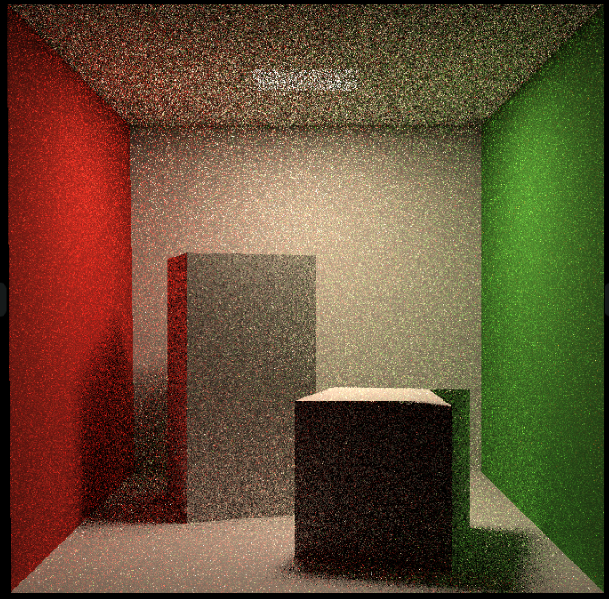
作业 7 - Path Tracing
要求
实现路径追踪,主要根据如下伪代码流程:
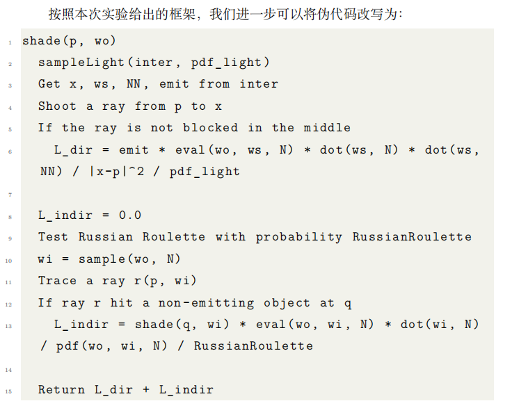
注意点:
- 计算 L_dir 的时候,第二个点乘 ws 需要 * -1,因为 ws 是 Shadingpoint 到光源的向量,参考下图
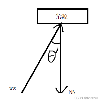
- 在
hitPoint上加上EPSLON * N,如果不这样,那么之后判断光线是否被遮挡会有问题(会认为被自己遮挡),然后出现下图的问题
- 计算射线到光源中间有无遮挡的时候不能直接判断
intersection.happened,因为命中光源时也会为 true,需要判断命中点是否满足hasEmission
总体流程如下:
- 从像素打出射线,检查射线是否命中,命中则继续下一步,反之结束
- 对光源表面进行采样,得到一个采样的交点 Intersection 和光源的 pdf
- 检查光源采样点和像素射线交点,两点之间是否有其他物体遮挡,没有遮挡则可计算直接光
- 计算俄罗斯轮盘赌概率,如果成功进行下一步
- 按照像素射线交点材质的性质,给定像素射线入射方向与交点法向量,用某种分布采样一个出射方向,这里是漫反射
- 有了出射方向和交点,得到新的射线,计算是否有命中
- 如果命中了非光源,计算新射线命中交点给原来像素射线交点带来的间接光
- 最后将直接光和间接光结合,得到最初命中的位置的颜色
// Implementation of Path Tracing Vector3f Scene::castRay(const Ray &ray, int depth) const { // TO DO Implement Path Tracing Algorithm here Vector3f l_indir{ 0.f }; Vector3f l_dir{0.f}; Intersection ray_inter = intersect(ray); if (!ray_inter.happened) { return l_dir + l_indir; } float pdf_light; Intersection light_inter; sampleLight(light_inter, pdf_light); Vector3f N = ray_inter.normal; Vector3f x = light_inter.coords; Vector3f wo = ray.direction; Vector3f p = ray_inter.coords; Vector3f ws = (x - p).normalized(); // shoot a ray from p to x Ray ray_light_to_p = Ray(p + EPSILON * N, ws); auto rpx_inter = intersect(ray_light_to_p); Vector3f NN = rpx_inter.normal; Material* m = ray_inter.m; // if the ray is not blocked in the middle if(rpx_inter.happened && rpx_inter.m->hasEmission()){ l_dir = rpx_inter.m->getEmission() * m->eval(wo, ws, N) * dotProduct(ws, N) \ * dotProduct(-ws, NN) / (rpx_inter.distance) / pdf_light; } // Test Russian Roulette with probability RussianRoulette if (get_random_float() <= RussianRoulette) { Vector3f wi = (m->sample(wo, N)).normalized(); Ray rpwi(p, wi); auto rpwi_inter = intersect(rpwi); if (rpwi_inter.happened && !rpwi_inter.m->hasEmission()) { l_indir = castRay(rpwi, depth + 1) * m->eval(wo, wi, N) * dotProduct(wi, N) \ / m->pdf(wo, wi, N) / RussianRoulette; } } return m->getEmission() + l_dir + l_indir; }
提高项
效率优化
- 获取随机数的接口中的局部变量频繁创建耗时较高,可以改为 static
inline float get_random_float() { static std::random_device dev; static std::mt19937 rng(dev()); static std::uniform_real_distribution<float> dist(0.f, 1.f); // distribution in range [1, 6] return dist(rng); }
- 增加多线程,每个像素计算着色具有良好局部性,没有临界区,所以将屏幕像素分批分多个线程同时进行渲染即可
// change the spp value to change sample ammount int spp = 512; int worker_num = 16; std::mutex lock; std::vector<std::thread> threads(worker_num); std::cout << "SPP: " << spp << "\n"; int height_gap = scene.height / worker_num; // ÐèÒª¿ÉÒÔ±» 8 Õû³ý auto worker = [&](int start_height, int length) { for (uint32_t j = start_height; j < start_height + length; ++j) { for (uint32_t i = 0; i < scene.width; ++i) { // generate primary ray direction float x = (2 * (i + 0.5) / (float)scene.width - 1) * imageAspectRatio * scale; float y = (1 - 2 * (j + 0.5) / (float)scene.height) * scale; Vector3f dir = normalize(Vector3f(-x, y, 1)); int frame_index = j * scene.width + i; float dspp = 1.0f / spp; for (int k = 0; k < spp; k++) { framebuffer[frame_index] += scene.castRay(Ray(eye_pos, dir), 0) * dspp; } } } }; for (int i = 0; i < worker_num; i++) { threads[i] = std::thread(worker, i * height_gap, height_gap); } for (int i = 0; i < threads.size(); i++) { threads[i].join(); }
这里原本有个输出进度的,由于多线程统计进度比较麻烦,直接去掉了
3. 微表面材质的计算,这里暂时对我来说超纲了,后续再补充...Orz
参考资料
作业 8 - 质点弹簧系统
由于本次作业用到了一些 unix 的接口,所以换到了 ubuntu 环境下开发
要求
构造两条 Rope,Rope 分别用 显式/半隐式欧拉法 和 显式 Verlet ,比较两者的区别,主要实现内容如下:
• rope.cpp 中的 Rope::rope(...)
• rope.cpp 中的 void Rope::simulateEuler(...)
• rope.cpp 中的 void Rope::simulateVerlet(...)
思路
构造 Rope
首先构造 Rope,Rope 的构造函数如下:
Rope::Rope(Vector2D start, Vector2D end, int num_nodes, float node_mass, float k, vector<int> pinned_nodes)
主要就是绳子的两端坐标,质点数量,质点的质量,还有胡克定律的系数 k,pinned_nodes 表示对应的质点是不动的,不然就会出现绳子直接掉下去的情况,需要有一个固定点,默认框架中 pinned_nodes 指定了第一个质点为固定点。
因此思路比较简单,就是遍历 num_nodes 次,每次构造一个质点,每两个质点 Mass 构造一根弹簧 Spring
Rope::Rope(Vector2D start, Vector2D end, int num_nodes, float node_mass, float k, vector<int> pinned_nodes) { // TODO (Part 1): Create a rope starting at `start`, ending at `end`, and containing `num_nodes` nodes. for(int i=0; i<num_nodes; ++i) { Vector2D pos = start + (end - start) * ((double)i / ((double)num_nodes - 1.0)); masses.push_back(new Mass(pos, node_mass, false)); } for(int i=0; i<num_nodes-1; ++i) { springs.push_back(new Spring(masses[i], masses[i+1], k)); } // Comment-in this part when you implement the constructor for (auto &i : pinned_nodes) { masses[i]->pinned = true; } }
显式/半隐式欧拉法
首先根据 ,只要计算出质点总受力 ,除以质点的质量 就可以得到质点的速度 。质点的受力分为两部分 : 重力 和 胡克定律计算得出的弹簧力。胡克定律如下:
a b 表示质点坐标,l 表示弹簧长度,k 为胡克定律常数系数。计算出 总受力 再施加给质点即可。
- 显式欧拉法 :
物体下一时刻位置 = 当前时刻位置 + 当前时刻速度 * 时间 - 半隐式欧拉法:
物体下一时刻位置 = 当前时刻位置 + 下一时刻速度 * 时间,然后利用当前时刻的位置 加上下一时刻的速度 , 表示时间,就可以得到下一时刻的位置
最后计算如下:
void Rope::simulateVerlet(float delta_t, Vector2D gravity) { for (auto &s : springs) { // TODO (Part 3): Simulate one timestep of the rope using explicit Verlet (solving constraints) auto mod_ab = (s->m1->position - s->m2->position).norm(); s->m1->forces += -s->k * (s->m1->position - s->m2->position) / mod_ab * (mod_ab - s->rest_length); s->m2->forces += -s->k * (s->m2->position - s->m1->position) / mod_ab * (mod_ab - s->rest_length); } float damping_factor = 0.00005; for (auto &m : masses) { if (!m->pinned) { Vector2D temp_position = m->position; // TODO (Part 3.1): Set the new position of the rope mass auto a = m->forces / m->mass + gravity; // TODO (Part 4): Add global Verlet damping m->position = temp_position + (1 - damping_factor) * (temp_position - m->last_position) + a * delta_t * delta_t; m->last_position = temp_position; } // Reset all forces on each mass m->forces = Vector2D(0, 0); } }
显式 Verlet
Verlet 是另一种精确求解所有约束的方法。这种方法的优点是只处理仿真中顶点的位置并且保证四阶精度。和欧拉法不同,Verlet 积分按如下的方式来更新下一步位置:
对比上一步主要替换质点更新位置的流程
void Rope::simulateVerlet(float delta_t, Vector2D gravity) { for (auto &s : springs) { // TODO (Part 3): Simulate one timestep of the rope using explicit Verlet (solving constraints) auto mod_ab = (s->m1->position - s->m2->position).norm(); s->m1->forces += -s->k * (s->m1->position - s->m2->position) / mod_ab * (mod_ab - s->rest_length); s->m2->forces += -s->k * (s->m2->position - s->m1->position) / mod_ab * (mod_ab - s->rest_length); } for (auto &m : masses) { if (!m->pinned) { Vector2D temp_position = m->position; // TODO (Part 3.1): Set the new position of the rope mass auto a = m->forces / m->mass + gravity; // TODO (Part 4): Add global Verlet damping m->position = temp_position + (temp_position - m->last_position) + a * delta_t * delta_t; m->last_position = temp_position; } // Reset all forces on each mass m->forces = Vector2D(0, 0); } } }
阻尼
增加阻尼系数 float damping_factor = 0.00005f,因为动能会因摩擦而减小,不可能出现无限跳动的弹簧
void Rope::simulateVerlet(float delta_t, Vector2D gravity) { for (auto &s : springs) { // TODO (Part 3): Simulate one timestep of the rope using explicit Verlet (solving constraints) auto mod_ab = (s->m1->position - s->m2->position).norm(); s->m1->forces += -s->k * (s->m1->position - s->m2->position) / mod_ab * (mod_ab - s->rest_length); s->m2->forces += -s->k * (s->m2->position - s->m1->position) / mod_ab * (mod_ab - s->rest_length); } float damping_factor = 0.00005; for (auto &m : masses) { if (!m->pinned) { Vector2D temp_position = m->position; // TODO (Part 3.1): Set the new position of the rope mass auto a = m->forces / m->mass + gravity; // TODO (Part 4): Add global Verlet damping m->position = temp_position + (1 - damping_factor) * (temp_position - m->last_position) + a * delta_t * delta_t; m->last_position = temp_position; } // Reset all forces on each mass m->forces = Vector2D(0, 0); } } }


【推荐】国内首个AI IDE,深度理解中文开发场景,立即下载体验Trae
【推荐】编程新体验,更懂你的AI,立即体验豆包MarsCode编程助手
【推荐】抖音旗下AI助手豆包,你的智能百科全书,全免费不限次数
【推荐】轻量又高性能的 SSH 工具 IShell:AI 加持,快人一步
· 分享4款.NET开源、免费、实用的商城系统
· 全程不用写代码,我用AI程序员写了一个飞机大战
· MongoDB 8.0这个新功能碉堡了,比商业数据库还牛
· 白话解读 Dapr 1.15:你的「微服务管家」又秀新绝活了
· 上周热点回顾(2.24-3.2)