esp32 espi库驱动 ili9481 测试xpt2046电阻屏触控功能
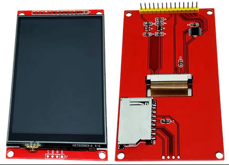
这次是驱动9481 买了屏一年后才搞明白 囧 踩了几个坑 这个屏vcc只能接3.3v 接5v无法使用 屏幕白屏过一会出现浅色圆圈
参考这位大神的帖子 数字城镇 - ESP32 配备 ILI9481 SPI 液晶触摸屏还是 ILI9486? (digitaltown.co.uk) 不过9481 9486 9488的3.5寸屏外观都是一模一样的 看不出来区别
9418的spi频率不高,默认的40m没反应 最后尝试用10m成功了
xpt2046的spi频率也不能太高,太高不准
setup.h的几个改动
// For ESP32 Dev board (only tested with ILI9341 display)
// The hardware SPI can be mapped to any pins  针脚定义


#define TFT_MISO 19
#define TFT_MOSI 23
#define TFT_SCLK 22
#define TFT_CS   0 // Chip select control pin
#define TFT_DC    2  // Data Command control pin
#define TFT_RST   4  // Reset pin (could connect to RST pin)    BL接3.3V
// #define TFT_RST  -1  // Set TFT_RST to -1 if display RESET is connected to ESP32 board RST


#define TOUCH_CS 21     // Chip select pin (T_CS) of touch screen     TCS针脚接esp32  的21
触控的TCS接31,其他几个针脚跟屏幕的并联起来 pen(中断)不接
// #define SPI_FREQUENCY   1000000
// #define SPI_FREQUENCY   5000000
// #define SPI_FREQUENCY   10000000
#define SPI_FREQUENCY  15999999
// #define SPI_FREQUENCY  20000000
// #define SPI_FREQUENCY  27000000
//  #define SPI_FREQUENCY  40000000  //如果有问题可以尝试降低频率  经过尝试用15.9M是spi的极限了
// #define SPI_FREQUENCY  55000000 // STM32 SPI1 only (SPI2 maximum is 27MHz)
// #define SPI_FREQUENCY  80000000

// Optional reduced SPI frequency for reading TFT
#define SPI_READ_FREQUENCY  20000000

// The XPT2046 requires a lower SPI clock rate of 2.5MHz so we define that here:
#define SPI_TOUCH_FREQUENCY  600000  //这里只用600k的spi clock频率   再高测试触摸位置不准
最终针脚接法
vcc 3.3v
gnd gnd
cs 0
rst 4
dc 2
sdi 23 TDI
sck 22 tck
bl 3.3v
sdo 19 TDO
TCS 21
关于spi频率 网上的解释,所以实际的频率只会是250的整数倍 我尝试把ili9231的频率改成7999999,也可以运行 也能感受到刷新确实快了
中文翻译:【源于谷歌】
我想要更好的性能和更快的更新!
您可以更改的SPI频率(超频显示)编辑/etc/modprobe.d/adafruit.conf和更改选项行:
fbtft_device名= adafruitrt28选择旋转=90频率=62000000 FPS=60
这里的东西,郫县只支持SPI频率固定的数量。因此,调整的数量一点也不会做任何事情。内核将圆的数目为最接近的值。你总是会得到频率是250MHz的用偶数分。这是唯一的SPI频率这个内核支持
15625000(a.k.a16000000=16兆赫)
17857142(亦称18000000=18兆赫)
20833333(a.k.a2100=21兆赫)
25,000,000(=25兆赫)
31250000(a.k.a32000000=32MHz的)
41666666(a.k.a4200=在42MHz)
62,500,000(a.k.a62000000=62MHz)
所以,如果你把4800万的速度,你就不会真正得到48MHz的,你居然只得到大约为42MHz,因为它被舍去。我们很好地测试了这款显示器具有32MHz的,我们认为。但是你可以把在42MHz,甚至尝试62MHz,它会更新更快
你可以调整的帧率(每秒帧数)是20〜60和频率高达62MHz的性能和速度的权衡。重新引导每个编辑后,以确保设置正确加载。有一个权衡,如果你要求更高的FPS你要加载的内核更多的是因为它试图保持显示更新。
最终的setup。h
//                            USER DEFINED SETTINGS
//   Set driver type, fonts to be loaded, pins used and SPI control method etc
//
//   See the User_Setup_Select.h file if you wish to be able to define multiple
//   setups and then easily select which setup file is used by the compiler.
//
//   If this file is edited correctly then all the library example sketches should
//   run without the need to make any more changes for a particular hardware setup!
//   Note that some sketches are designed for a particular TFT pixel width/height


// ##################################################################################
//
// Section 1. Call up the right driver file and any options for it
//
// ##################################################################################

// Define STM32 to invoke optimised processor support (only for STM32)
//#define STM32

// Defining the STM32 board allows the library to optimise the performance
// for UNO compatible "MCUfriend" style shields
//#define NUCLEO_64_TFT
//#define NUCLEO_144_TFT

// STM32 8 bit parallel only:
// If STN32 Port A or B pins 0-7 are used for 8 bit parallel data bus bits 0-7
// then this will improve rendering performance by a factor of ~8x
//#define STM_PORTA_DATA_BUS
//#define STM_PORTB_DATA_BUS

// Tell the library to use 8 bit parallel mode (otherwise SPI is assumed)
//#define TFT_PARALLEL_8_BIT

// Display type -  only define if RPi display
//#define RPI_DISPLAY_TYPE // 20MHz maximum SPI

// Only define one driver, the other ones must be commented out
// #define ILI9341_DRIVER       // Generic driver for common displays
// #define ILI9341_2_DRIVER     // Alternative ILI9341 driver, see https://github.com/Bodmer/TFT_eSPI/issues/1172
// #define ST7735_DRIVER      // Define additional parameters below for this display
//#define ILI9163_DRIVER     // Define additional parameters below for this display
//#define S6D02A1_DRIVER
//#define RPI_ILI9486_DRIVER // 20MHz maximum SPI
//#define HX8357D_DRIVER
#define ILI9481_DRIVER
// #define ILI9486_DRIVER   //9481跟9486如果选错的话正好显示的内容是反的
// #define ILI9488_DRIVER     // WARNING: Do not connect ILI9488 display SDO to MISO if other devices share the SPI bus (TFT SDO does NOT tristate when CS is high)
//#define ST7789_DRIVER      // Full configuration option, define additional parameters below for this display
//#define ST7789_2_DRIVER    // Minimal configuration option, define additional parameters below for this display
//#define R61581_DRIVER
//#define RM68140_DRIVER
//#define ST7796_DRIVER
//#define SSD1351_DRIVER
//#define SSD1963_480_DRIVER
//#define SSD1963_800_DRIVER
//#define SSD1963_800ALT_DRIVER
//#define ILI9225_DRIVER
//#define GC9A01_DRIVER

// Some displays support SPI reads via the MISO pin, other displays have a single
// bi-directional SDA pin and the library will try to read this via the MOSI line.
// To use the SDA line for reading data from the TFT uncomment the following line:

#define TFT_SDA_READ      // This option is for ESP32 ONLY, tested with ST7789 and GC9A01 display only

// For ST7735, ST7789 and ILI9341 ONLY, define the colour order IF the blue and red are swapped on your display
// Try ONE option at a time to find the correct colour order for your display

//  #define TFT_RGB_ORDER TFT_RGB  // Colour order Red-Green-Blue
//  #define TFT_RGB_ORDER TFT_BGR  // Colour order Blue-Green-Red

// For M5Stack ESP32 module with integrated ILI9341 display ONLY, remove // in line below

//  #define M5STACK

// For ST7789, ST7735, ILI9163 and GC9A01 ONLY, define the pixel width and height in portrait orientation   像素高宽
// #define TFT_WIDTH  80
// #define TFT_WIDTH  128
// #define TFT_WIDTH  240 // ST7789 240 x 240 and 240 x 320
// #define TFT_HEIGHT 160
// #define TFT_HEIGHT 128
// #define TFT_HEIGHT 240 // ST7789 240 x 240
// #define TFT_HEIGHT 320 // ST7789 240 x 320
// #define TFT_HEIGHT 240 // GC9A01 240 x 240

// For ST7735 ONLY, define the type of display, originally this was based on the
// colour of the tab on the screen protector film but this is not always true, so try
// out the different options below if the screen does not display graphics correctly,
// e.g. colours wrong, mirror images, or stray pixels at the edges.
// Comment out ALL BUT ONE of these options for a ST7735 display driver, save this
// this User_Setup file, then rebuild and upload the sketch to the board again:
// #define ST7735_INITB
// #define ST7735_GREENTAB
// #define ST7735_GREENTAB2
// #define ST7735_GREENTAB3
// #define ST7735_GREENTAB128    // For 128 x 128 display
// #define ST7735_GREENTAB160x80 // For 160 x 80 display (BGR, inverted, 26 offset)
// #define ST7735_REDTAB
// #define ST7735_BLACKTAB
// #define ST7735_REDTAB160x80   // For 160 x 80 display with 24 pixel offset

// If colours are inverted (white shows as black) then uncomment one of the next
// 2 lines try both options, one of the options should correct the inversion.

// #define TFT_INVERSION_ON
// #define TFT_INVERSION_OFF


// ##################################################################################
//
// Section 2. Define the pins that are used to interface with the display here
//
// ##################################################################################

// If a backlight control signal is available then define the TFT_BL pin in Section 2
// below. The backlight will be turned ON when tft.begin() is called, but the library
// needs to know if the LEDs are ON with the pin HIGH or LOW. If the LEDs are to be
// driven with a PWM signal or turned OFF/ON then this must be handled by the user
// sketch. e.g. with digitalWrite(TFT_BL, LOW);

// #define TFT_BL   32            // LED back-light control pin
// #define TFT_BACKLIGHT_ON HIGH  // Level to turn ON back-light (HIGH or LOW)


// We must use hardware SPI, a minimum of 3 GPIO pins is needed.
// Typical setup for ESP8266 NodeMCU ESP-12 is :
//
// Display SDO/MISO  to NodeMCU pin D6 (or leave disconnected if not reading TFT)
// Display LED       to NodeMCU pin VIN (or 5V, see below)
// Display SCK       to NodeMCU pin D5
// Display SDI/MOSI  to NodeMCU pin D7
// Display DC (RS/AO)to NodeMCU pin D3
// Display RESET     to NodeMCU pin D4 (or RST, see below)
// Display CS        to NodeMCU pin D8 (or GND, see below)
// Display GND       to NodeMCU pin GND (0V)
// Display VCC       to NodeMCU 5V or 3.3V
//
// The TFT RESET pin can be connected to the NodeMCU RST pin or 3.3V to free up a control pin
//
// The DC (Data Command) pin may be labelled AO or RS (Register Select)
//
// With some displays such as the ILI9341 the TFT CS pin can be connected to GND if no more
// SPI devices (e.g. an SD Card) are connected, in this case comment out the #define TFT_CS
// line below so it is NOT defined. Other displays such at the ST7735 require the TFT CS pin
// to be toggled during setup, so in these cases the TFT_CS line must be defined and connected.
//
// The NodeMCU D0 pin can be used for RST
//
//
// Note: only some versions of the NodeMCU provide the USB 5V on the VIN pin
// If 5V is not available at a pin you can use 3.3V but backlight brightness
// will be lower.


// ###### EDIT THE PIN NUMBERS IN THE LINES FOLLOWING TO SUIT YOUR ESP8266 SETUP ######

// For NodeMCU - use pin numbers in the form PIN_Dx where Dx is the NodeMCU pin designation
// #define TFT_CS   PIN_D8  // Chip select control pin D8
// #define TFT_DC   PIN_D3  // Data Command control pin
// #define TFT_RST  PIN_D4  // Reset pin (could connect to NodeMCU RST, see next line)
//#define TFT_RST  -1    // Set TFT_RST to -1 if the display RESET is connected to NodeMCU RST or 3.3V

//#define TFT_BL PIN_D1  // LED back-light (only for ST7789 with backlight control pin)

//#define TOUCH_CS PIN_D2     // Chip select pin (T_CS) of touch screen

//#define TFT_WR PIN_D2       // Write strobe for modified Raspberry Pi TFT only


// ######  FOR ESP8266 OVERLAP MODE EDIT THE PIN NUMBERS IN THE FOLLOWING LINES  ######

// Overlap mode shares the ESP8266 FLASH SPI bus with the TFT so has a performance impact
// but saves pins for other functions. It is best not to connect MISO as some displays
// do not tristate that line when chip select is high!
// On NodeMCU 1.0 SD0=MISO, SD1=MOSI, CLK=SCLK to connect to TFT in overlap mode
// On NodeMCU V3  S0 =MISO, S1 =MOSI, S2 =SCLK
// In ESP8266 overlap mode the following must be defined

//#define TFT_SPI_OVERLAP

// In ESP8266 overlap mode the TFT chip select MUST connect to pin D3
//#define TFT_CS   PIN_D3
//#define TFT_DC   PIN_D5  // Data Command control pin
//#define TFT_RST  PIN_D4  // Reset pin (could connect to NodeMCU RST, see next line)
//#define TFT_RST  -1  // Set TFT_RST to -1 if the display RESET is connected to NodeMCU RST or 3.3V


// ###### EDIT THE PIN NUMBERS IN THE LINES FOLLOWING TO SUIT YOUR ESP32 SETUP   ######

// For ESP32 Dev board (only tested with ILI9341 display)
// The hardware SPI can be mapped to any pins  针脚定义


#define TFT_MISO 19
#define TFT_MOSI 23
#define TFT_SCLK 22
#define TFT_CS   0 // Chip select control pin
#define TFT_DC    2  // Data Command control pin
#define TFT_RST   4  // Reset pin (could connect to RST pin)
// #define TFT_RST  -1  // Set TFT_RST to -1 if display RESET is connected to ESP32 board RST

// For ESP32 Dev board (only tested with GC9A01 display)
// The hardware SPI can be mapped to any pins

//#define TFT_MOSI 15 // In some display driver board, it might be written as "SDA" and so on.
//#define TFT_SCLK 14
//#define TFT_CS   5  // Chip select control pin
//#define TFT_DC   27  // Data Command control pin
//#define TFT_RST  33  // Reset pin (could connect to Arduino RESET pin)
//#define TFT_BL   22  // LED back-light

#define TOUCH_CS 21     // Chip select pin (T_CS) of touch screen

//#define TFT_WR 22    // Write strobe for modified Raspberry Pi TFT only

// For the M5Stack module use these #define lines
// #define TFT_MISO 19
// #define TFT_MOSI 23
// #define TFT_SCLK 18
// #define TFT_CS   14  // Chip select control pin
// #define TFT_DC   27  // Data Command control pin
// #define TFT_RST  33  // Reset pin (could connect to Arduino RESET pin)
// #define TFT_BL   32  // LED back-light (required for M5Stack)

// ######       EDIT THE PINs BELOW TO SUIT YOUR ESP32 PARALLEL TFT SETUP        ######

// The library supports 8 bit parallel TFTs with the ESP32, the pin
// selection below is compatible with ESP32 boards in UNO format.
// Wemos D32 boards need to be modified, see diagram in Tools folder.
// Only ILI9481 and ILI9341 based displays have been tested!

// Parallel bus is only supported for the STM32 and ESP32
// Example below is for ESP32 Parallel interface with UNO displays

// Tell the library to use 8 bit parallel mode (otherwise SPI is assumed)
//#define TFT_PARALLEL_8_BIT

// The ESP32 and TFT the pins used for testing are:
//#define TFT_CS   33  // Chip select control pin (library pulls permanently low
//#define TFT_DC   15  // Data Command control pin - must use a pin in the range 0-31
//#define TFT_RST  32  // Reset pin, toggles on startup

//#define TFT_WR    4  // Write strobe control pin - must use a pin in the range 0-31
//#define TFT_RD    2  // Read strobe control pin

//#define TFT_D0   12  // Must use pins in the range 0-31 for the data bus
//#define TFT_D1   13  // so a single register write sets/clears all bits.
//#define TFT_D2   26  // Pins can be randomly assigned, this does not affect
//#define TFT_D3   25  // TFT screen update performance.
//#define TFT_D4   17
//#define TFT_D5   16
//#define TFT_D6   27
//#define TFT_D7   14

// ######       EDIT THE PINs BELOW TO SUIT YOUR STM32 SPI TFT SETUP        ######

// The TFT can be connected to SPI port 1 or 2
//#define TFT_SPI_PORT 1 // SPI port 1 maximum clock rate is 55MHz
//#define TFT_MOSI PA7
//#define TFT_MISO PA6
//#define TFT_SCLK PA5

//#define TFT_SPI_PORT 2 // SPI port 2 maximum clock rate is 27MHz
//#define TFT_MOSI PB15
//#define TFT_MISO PB14
//#define TFT_SCLK PB13

// Can use Ardiuno pin references, arbitrary allocation, TFT_eSPI controls chip select
//#define TFT_CS   D5 // Chip select control pin to TFT CS
//#define TFT_DC   D6 // Data Command control pin to TFT DC (may be labelled RS = Register Select)
//#define TFT_RST  D7 // Reset pin to TFT RST (or RESET)
// OR alternatively, we can use STM32 port reference names PXnn
//#define TFT_CS   PE11 // Nucleo-F767ZI equivalent of D5
//#define TFT_DC   PE9  // Nucleo-F767ZI equivalent of D6
//#define TFT_RST  PF13 // Nucleo-F767ZI equivalent of D7

//#define TFT_RST  -1   // Set TFT_RST to -1 if the display RESET is connected to processor reset
                        // Use an Arduino pin for initial testing as connecting to processor reset
                        // may not work (pulse too short at power up?)

// ##################################################################################
//
// Section 3. Define the fonts that are to be used here
//
// ##################################################################################

// Comment out the #defines below with // to stop that font being loaded
// The ESP8366 and ESP32 have plenty of memory so commenting out fonts is not
// normally necessary. If all fonts are loaded the extra FLASH space required is
// about 17Kbytes. To save FLASH space only enable the fonts you need!

#define LOAD_GLCD   // Font 1. Original Adafruit 8 pixel font needs ~1820 bytes in FLASH
#define LOAD_FONT2  // Font 2. Small 16 pixel high font, needs ~3534 bytes in FLASH, 96 characters
#define LOAD_FONT4  // Font 4. Medium 26 pixel high font, needs ~5848 bytes in FLASH, 96 characters
#define LOAD_FONT6  // Font 6. Large 48 pixel font, needs ~2666 bytes in FLASH, only characters 1234567890:-.apm
#define LOAD_FONT7  // Font 7. 7 segment 48 pixel font, needs ~2438 bytes in FLASH, only characters 1234567890:-.
#define LOAD_FONT8  // Font 8. Large 75 pixel font needs ~3256 bytes in FLASH, only characters 1234567890:-.
//#define LOAD_FONT8N // Font 8. Alternative to Font 8 above, slightly narrower, so 3 digits fit a 160 pixel TFT
#define LOAD_GFXFF  // FreeFonts. Include access to the 48 Adafruit_GFX free fonts FF1 to FF48 and custom fonts

// Comment out the #define below to stop the SPIFFS filing system and smooth font code being loaded
// this will save ~20kbytes of FLASH
#define SMOOTH_FONT


// ##################################################################################
//
// Section 4. Other options
//
// ##################################################################################

// Define the SPI clock frequency, this affects the graphics rendering speed. Too
// fast and the TFT driver will not keep up and display corruption appears.
// With an ILI9341 display 40MHz works OK, 80MHz sometimes fails
// With a ST7735 display more than 27MHz may not work (spurious pixels and lines)
// With an ILI9163 display 27 MHz works OK.

// #define SPI_FREQUENCY   1000000
// #define SPI_FREQUENCY   5000000
// #define SPI_FREQUENCY   10000000
#define SPI_FREQUENCY  15999999
// #define SPI_FREQUENCY  20000000
// #define SPI_FREQUENCY  27000000
//  #define SPI_FREQUENCY  40000000  //如果有问题可以尝试降低频率
// #define SPI_FREQUENCY  55000000 // STM32 SPI1 only (SPI2 maximum is 27MHz)
// #define SPI_FREQUENCY  80000000

// Optional reduced SPI frequency for reading TFT
#define SPI_READ_FREQUENCY  20000000

// The XPT2046 requires a lower SPI clock rate of 2.5MHz so we define that here:
#define SPI_TOUCH_FREQUENCY  600000

// The ESP32 has 2 free SPI ports i.e. VSPI and HSPI, the VSPI is the default.
// If the VSPI port is in use and pins are not accessible (e.g. TTGO T-Beam)
// then uncomment the following line:
//#define USE_HSPI_PORT

// Comment out the following #define if "SPI Transactions" do not need to be
// supported. When commented out the code size will be smaller and sketches will
// run slightly faster, so leave it commented out unless you need it!

// Transaction support is needed to work with SD library but not needed with TFT_SdFat
// Transaction support is required if other SPI devices are connected.

// Transactions are automatically enabled by the library for an ESP32 (to use HAL mutex)
// so changing it here has no effect

// #define SUPPORT_TRANSACTIONS
自带的校准触控校准程序
/*
  Sketch to generate the setup() calibration values, these are reported
  to the Serial Monitor.

  The sketch has been tested on the ESP8266 and screen with XPT2046 driver.
*/

#include <SPI.h>
#include <TFT_eSPI.h>      // Hardware-specific library

TFT_eSPI tft = TFT_eSPI(); // Invoke custom library

//------------------------------------------------------------------------------------------

void setup() {
  // Use serial port
  Serial.begin(115200);

  // Initialise the TFT screen
  tft.init();

  // Set the rotation to the orientation you wish to use in your project before calibration
  // (the touch coordinates returned then correspond to that rotation only)
  tft.setRotation(1);

  // Calibrate the touch screen and retrieve the scaling factors
  touch_calibrate();

/*
  // Replace above line with the code sent to Serial Monitor
  // once calibration is complete, e.g.:
  uint16_t calData[5] = { 286, 3534, 283, 3600, 6 };
  tft.setTouch(calData);
*/

  // Clear the screen
  tft.fillScreen(TFT_BLACK);
  tft.drawCentreString("Touch screen to test!",tft.width()/2, tft.height()/2, 2);
}

//------------------------------------------------------------------------------------------

void loop(void) {
  uint16_t x = 0, y = 0; // To store the touch coordinates

  // Pressed will be set true is there is a valid touch on the screen
  bool pressed = tft.getTouch(&x, &y);

  // Draw a white spot at the detected coordinates
  if (pressed) {
    tft.fillCircle(x, y, 2, TFT_WHITE);
    //Serial.print("x,y = ");
    //Serial.print(x);
    //Serial.print(",");
    //Serial.println(y);
  }
}

//------------------------------------------------------------------------------------------

// Code to run a screen calibration, not needed when calibration values set in setup()
void touch_calibrate()
{
  uint16_t calData[5];
  uint8_t calDataOK = 0;

  // Calibrate
  tft.fillScreen(TFT_BLACK);
  tft.setCursor(20, 0);
  tft.setTextFont(2);
  tft.setTextSize(1);
  tft.setTextColor(TFT_WHITE, TFT_BLACK);

  tft.println("Touch corners as indicated");

  tft.setTextFont(1);
  tft.println();

  tft.calibrateTouch(calData, TFT_MAGENTA, TFT_BLACK, 15);

  Serial.println(); Serial.println();
  Serial.println("// Use this calibration code in setup():");
  Serial.print("  uint16_t calData[5] = ");
  Serial.print("{ ");

  for (uint8_t i = 0; i < 5; i++)
  {
    Serial.print(calData[i]);
    if (i < 4) Serial.print(", ");
  }

  Serial.println(" };");
  Serial.print("  tft.setTouch(calData);");
  Serial.println(); Serial.println();

  tft.fillScreen(TFT_BLACK);

  tft.setTextColor(TFT_GREEN, TFT_BLACK);
  tft.println("Calibration complete!");
  tft.println("Calibration code sent to Serial port.");

  delay(4000);
}
实际视频 7.46 lPX:/ esp32驱动ili9481# 单片机 https://v.douyin.com/jN3VdS5/ 复制此链接,打开Dou音搜索,直接观看视频!
2.33 PkC:/ esp32+电阻屏触控测试# 单片机 https://v.douyin.com/jN3wj8k/ 复制此链接,打开Dou音搜索,直接观看视频!

 浙公网安备 33010602011771号