Verilog HDL刷题笔记(07)(Circuit-Combinational Logic-K-Map to Circuit)
知乎上有个详细的解答专栏:https://zhuanlan.zhihu.com/c_1131528588117385216
73.Implement the circuit described by the Karnaugh map below.
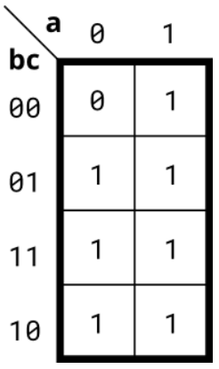
module top_module(
    input a,
    input b,
    input c,
    output out  );
    assign out = a | (~a)&c | b;
endmodule
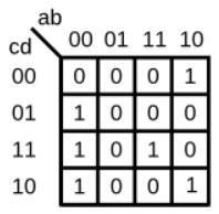
74.Implement the circuit described by the Karnaugh map below.
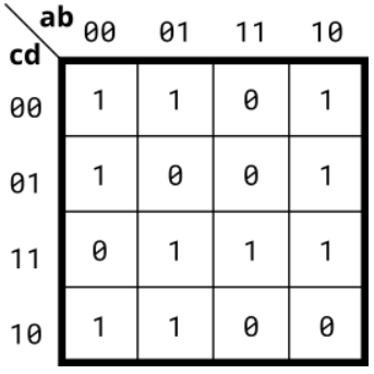
Try to simplify the k-map before coding it. Try both product-of-sums and sum-of-products forms. We can't check whether you have the optimal simplification of the k-map. But we can check if your reduction is equivalent, and we can check whether you can translate a k-map into a circuit.
module top_module(
    input a,
    input b,
    input c,
    input d,
    output out  );
    assign out = (~a&~d)|(~b&~c)|(~a&b&c)|(a&c&d);
endmodule
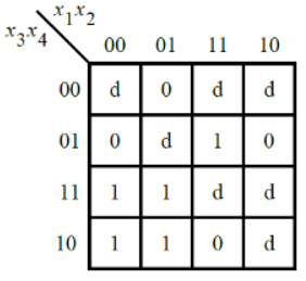
75.Implement the circuit described by the Karnaugh map below.
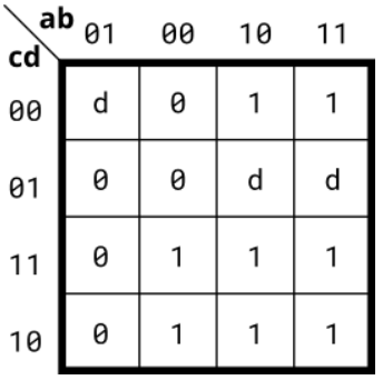
d即无关项;
module top_module(
    input a,
    input b,
    input c,
    input d,
    output out  );
    assign out = a&c | a&d | ~b&c | a&~c;
endmodule
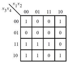
76.Implement the circuit described by the Karnaugh map below.
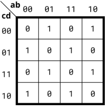
module top_module(
    input a,
    input b,
    input c,
    input d,
    output out  );
    assign out=a^b^c^d;
endmodule
77.A single-output digital system with four inputs (a,b,c,d) generates a logic-1 when 2, 7, or 15 appears on the inputs, and a logic-0 when 0, 1, 4, 5, 6, 9, 10, 13, or 14 appears. The input conditions for the numbers 3, 8, 11, and 12 never occur in this system. For example, 7 corresponds to a,b,c,d being set to 0,1,1,1, respectively.
Determine the output out_sop in minimum SOP form, and the output out_pos in minimum POS form.
module top_module (
    input a,
    input b,
    input c,
    input d,
    output out_sop,
    output out_pos
);
    assign out_sop = (c&d) | (~a&~b&c&~d);
    assign out_pos = c & (~b|d) & (~a|d);
endmodule
[PS]刷到这题才知道卡诺图有两种转化方式。。。
78.Consider the function f shown in the Karnaugh map below.Implement this function. d is don't-care, which means you may choose to output whatever value is convenient.
module top_module (
    input [4:1] x,
    output f );
    assign f = (~x[1]&x[3]) | x[2]&x[4];
endmodule
79.Consider the function f shown in the Karnaugh map below. Implement this function.
(The original exam question asked for simplified SOP and POS forms of the function.)
module top_module (
    input [4:1] x,
    output f
);
    assign f = ~x[1]&x[3] | ~x[2]&~x[4] | x[2]&x[3]&x[4];
endmodule
80.For the following Karnaugh map, give the circuit implementation using one 4-to-1 multiplexer and as many 2-to-1 multiplexers as required, but using as few as possible. You are not allowed to use any other logic gate and you must use a and b as the multiplexer selector inputs, as shown on the 4-to-1 multiplexer below.
You are implementing just the portion labelled top_module, such that the entire circuit (including the 4-to-1 mux) implements the K-map.

module top_module (
    input c,
    input d,
    output [3:0] mux_in
);
    assign mux_in[0]=d|c;
    assign mux_in[1]=1'b0;
    assign mux_in[2]=~d;
    assign mux_in[3]=c&d;
endmodule