HCIP-进阶实验06-多实例生成树安全部署
HCIP-ICT进阶实验06-多实例生成树安全部署
1 实验需求
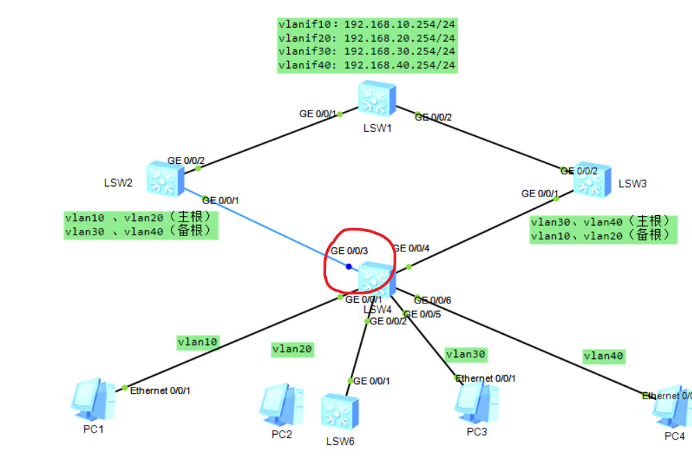
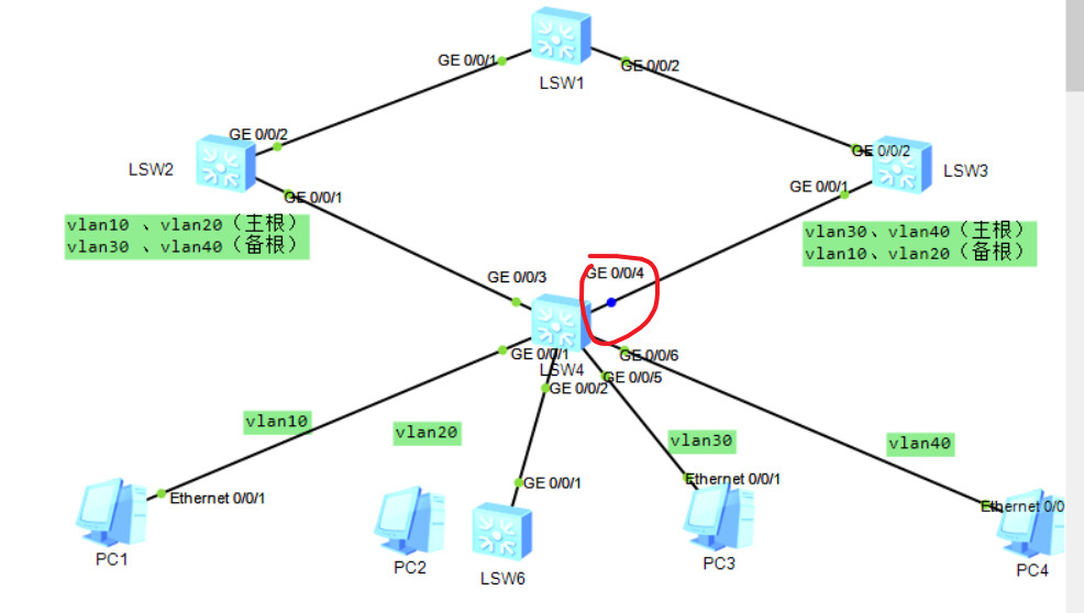
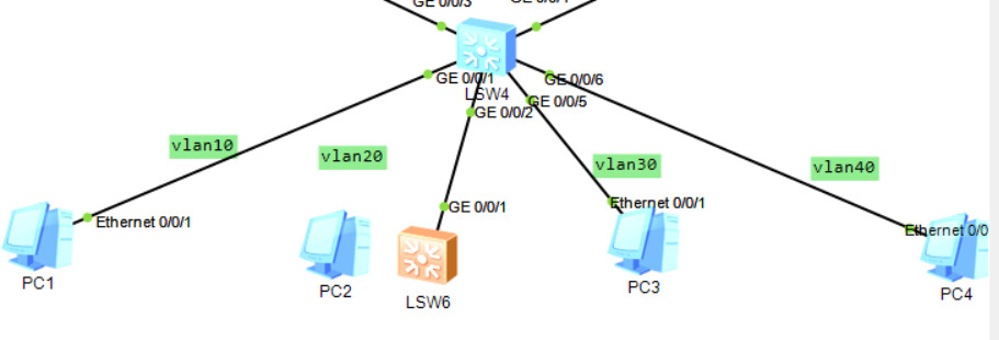
1.1 实验拓扑
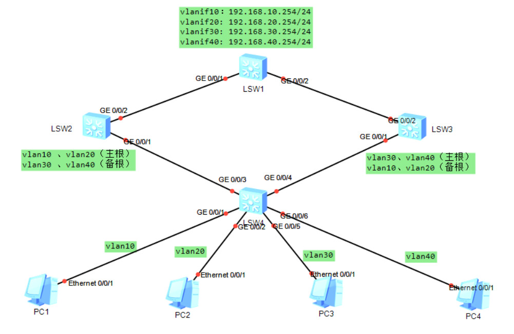
1.2 实验环境说明
IP地址规划表:
| 设备 | 接口 | IP 地址 | 备注 |
|---|---|---|---|
| SW1 | VLANIF10 | 192.168.10.254/24 | |
| VLANIF20 | 192.168.20.254/24 | ||
| VLANIF30 | 192.168.30.254/24 | ||
| VLANIF40 | 192.168.40.254/24 | ||
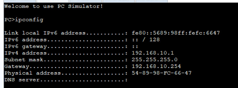
| PC1 | Ethernet0/0/1 | 192.168.10.1/24 | Vlan10 |
| PC2 | Ethernet0/0/1 | 192.168.20.1/24 | Vlan20 |
| PC3 | Ethernet0/0/1 | 192.168.30.1/24 | Vlan30 |
| PC4 | Ethernet0/0/1 | 192.168.40.1/24 | Vlan40 |
1.3 实验需求
本实验采用4台PC,4台交换机。认真分析实验需求,明确每步考查的知识点,并根据规划 IP 地址;拓扑搭建实验环境,确保端口都双UP后再进行下面步骤:
2 实验步骤
2.1 根据拓扑配置好相关接口的地址,交换机SW1为vlan10、vlan20、vlan30、vlan40的网关。
配置脚本
配置4台PC的ip地址、掩码、网关
配置验证
四台都验证一遍, 这里展示PC1的
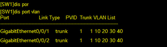
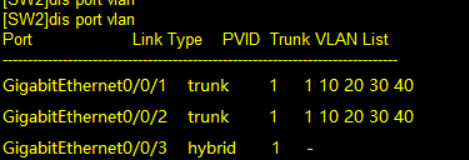
2.2 交换机之间起trunk,在交换机SW1、SW2、SW3、SW4创建VLAN 10、 20、 30、 40;并且把PC1划入VLAN10,PC2划入VLAN20,PC3划入VLAN30,PC4划入VLAN40。
配置脚本
SW1:
sy
sysname SW1
vlan batch 10 20 30 40
int vlanif 10
ip add 192.168.10.254 24
int vlanif 20
ip add 192.168.20.254 24
int vlanif 30
ip add 192.168.30.254 24
int vlanif 40
ip add 192.168.40.254 24
qu

int g0/0/1
port link-type trunk
port trunk allow-pass vlan 10 20 30 40
port trunk pvid vlan 1
qu

int g0/0/2
port link-type trunk
port trunk allow-pass vlan 10 20 30 40
port trunk pvid vlan 1
qu
SW2:
sy
sysname SW2
vlan batch 10 20 30 40

int g0/0/1
port link-type trunk
port trunk allow-pass vlan 10 20 30 40
port trunk pvid vlan 1
qu

int g0/0/2
port link-type trunk
port trunk allow-pass vlan 10 20 30 40
port trunk pvid vlan 1
qu
SW3:
sy
sysname SW3
vlan batch 10 20 30 40

int g0/0/1
port link-type trunk
port trunk allow-pass vlan 10 20 30 40
port trunk pvid vlan 1
qu

int g0/0/2
port link-type trunk
port trunk allow-pass vlan 10 20 30 40
port trunk pvid vlan 1
qu
SW4:
sy
sysname SW4
vlan batch 10 20 30 40

int g0/0/3
port link-type trunk
port trunk allow-pass vlan 10 20 30 40
port trunk pvid vlan 1
qu

int g0/0/4
port link-type trunk
port trunk allow-pass vlan 10 20 30 40
port trunk pvid vlan 1
qu

int g0/0/1
port link-type access
port default vlan 10
int g0/0/2
port link-type access
port default vlan 20
int g0/0/5
port link-type access
port default vlan 30
int g0/0/6
port link-type access
port default vlan 40
qu
本来下意识想配置vtp的, 但后来反应过来华为的设备不支持vtp, 只能手敲vlan, GVRP下次有空看看, 这段时间挺忙的...
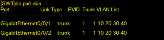
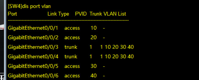
配置验证
dis port vlan
2.3 要求交换机之间使用MSTP生成树协议,并且SW2为vlan10、20的根桥,vlan 30、40的备份根桥,SW3为vlan30、40的根桥,vlan 10、20的备份根桥。最终实现vlan10、vlan20从sw4—>sw2—>sw1,vlan30、vlan40从sw4—>sw3—>sw1转发。
配置命令
SW1:
stp mode mstp

stp region-configuration
	region-name test
	revision-level 10
	instance 1 vlan 10 20
	instance 2 vlan 30 40
	active region-configuration
qu
SW2:
stp mode mstp

stp region-configuration
	region-name test
	revision-level 10
	instance 1 vlan 10 20
	instance 2 vlan 30 40
	active region-configuration
qu

stp instance 1 root primary
stp instance 2 root secondary
SW3:
stp mode mstp

stp region-configuration
	region-name test
	revision-level 10
	instance 1 vlan 10 20
	instance 2 vlan 30 40
	active region-configuration
qu

stp instance 2 root primary
stp instance 1 root secondary
SW4:
stp mode mstp

stp region-configuration
	region-name test
	revision-level 10
	instance 1 vlan 10 20
	instance 2 vlan 30 40
	active region-configuration
qu
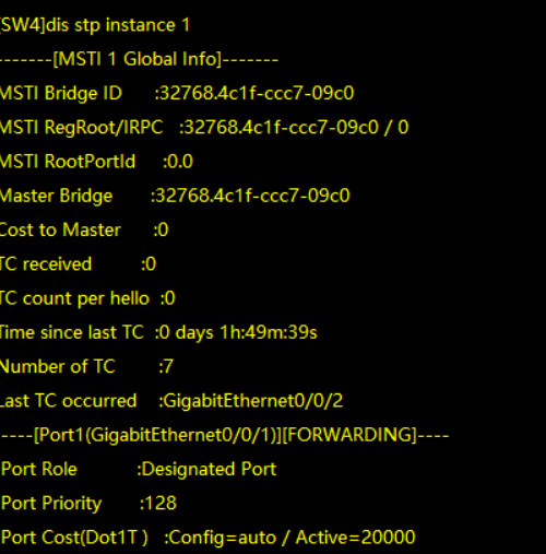
配置验证
查看stp的实例
dis stp instance instance-id
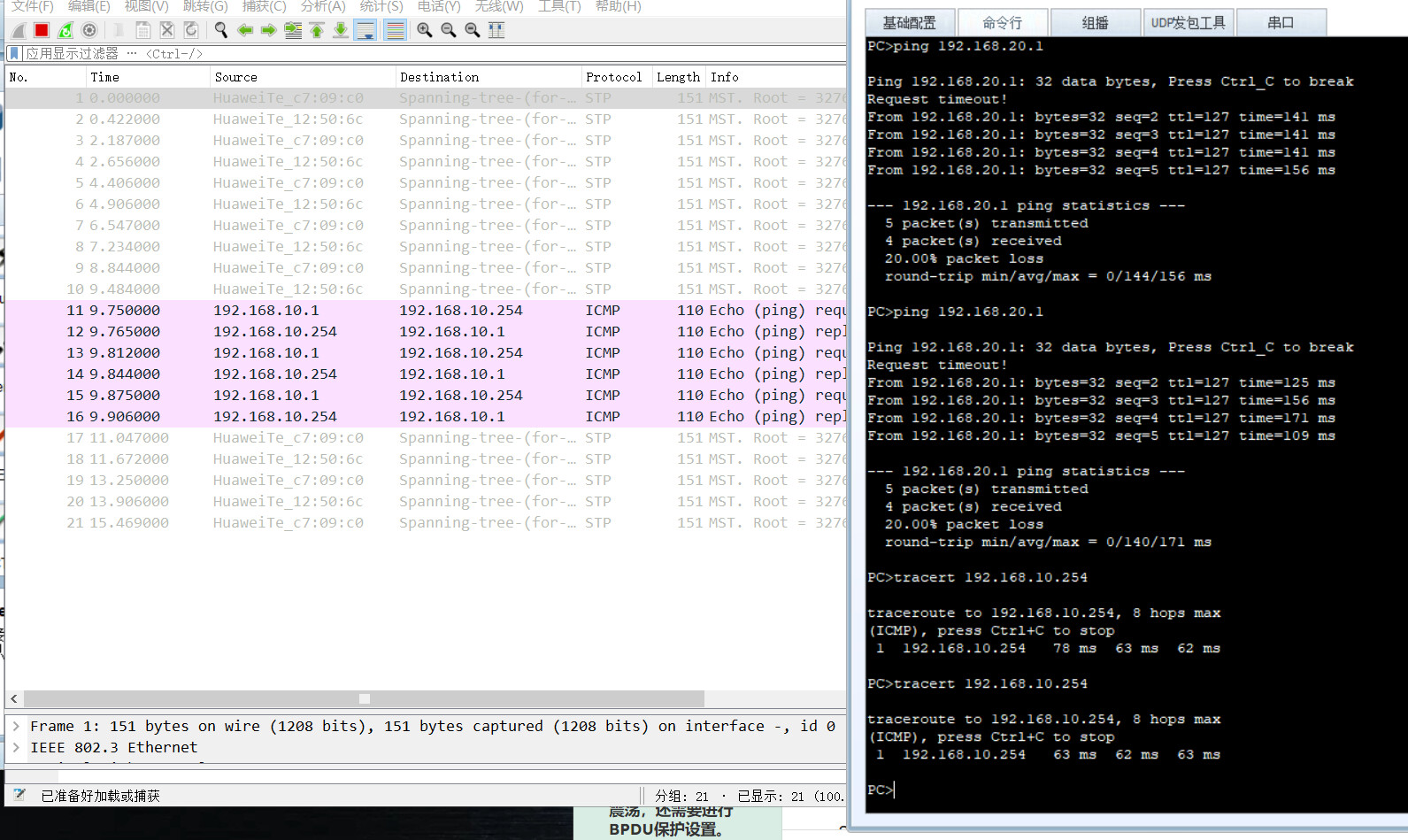
vlan 10:
tracert 192.168.10.254
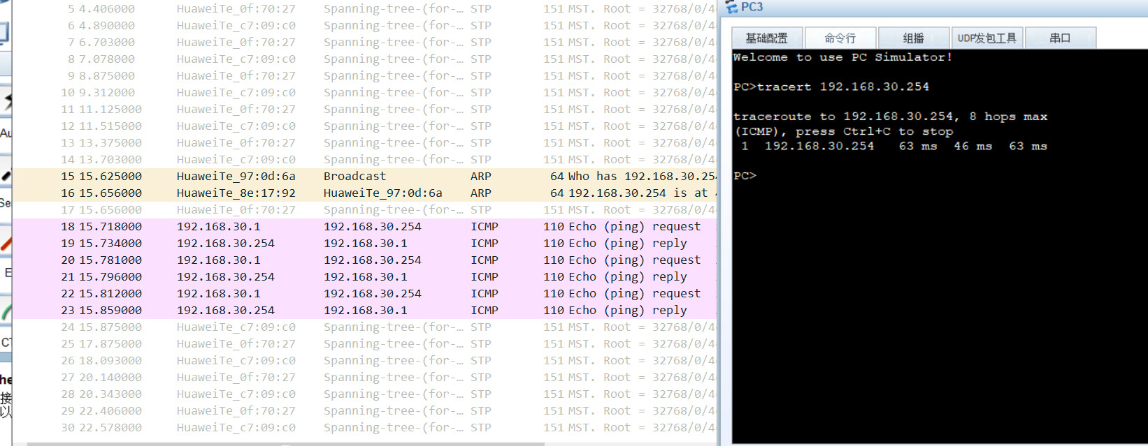
vlan 30:
tracert 192.168.30.254
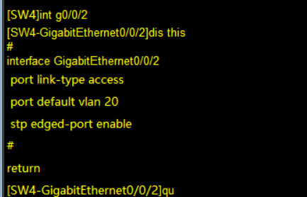
2.4 为了保证PC接入后快速进入数据的转发,需要在连接终端的链路配置边缘端口,同时为防止网络震荡,还需要进行BPDU保护设置。
配置脚本
SW4:
int g0/0/1
	stp edged-port enable
int g0/0/2
	stp edged-port enable
int g0/0/5
	stp edged-port enable
int g0/0/6
	stp edged-port enable
qu

stp bpdu-protection
error-down auto-recovery cause bpdu-protection interval 10
BPDU防护只会针对边缘端口开启;
最后一句配置时将被BPDU防护关闭的接口配置10s后自动重新打开.
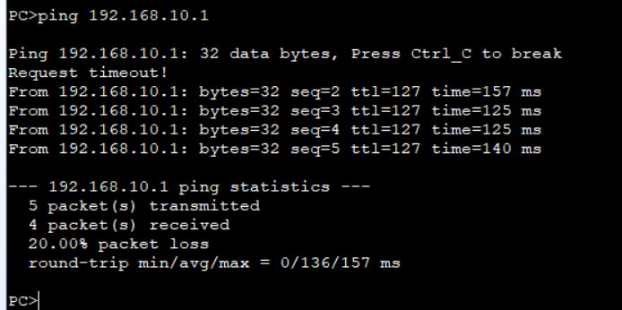
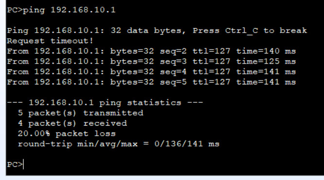
配置验证
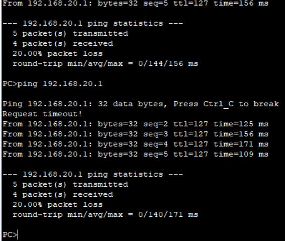
终端拔线再连接, ping通网络的速度缩短:
为配置边缘端口前:
四轮ping才通
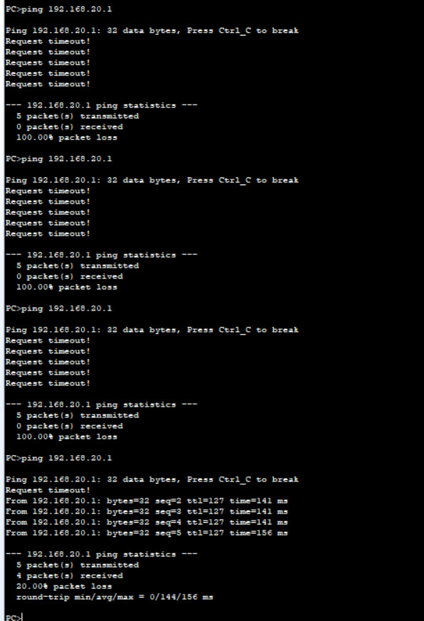
开启边缘端口后:
第一轮就能ping通, 效果还是很明显的!
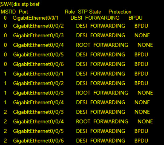
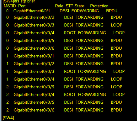
2.5 为了避免网络拥塞导致环路的发生,请在交换机上配置环路保护功能。
环路保护需要在根端口和AP端口配置.
配置脚本
SW4:
dis stp brief

int g0/0/4
	stp loop-protection
int g0/0/3
	stp loop-protection
qu
先查看哪些端口为AP端口
配置验证
配置前:
配置后:
问题
1 无法成功验证BPDU防护未开启时的状态
将一台终端替换为交换机:
未开启BPDU防护:
很遗憾, 我并不知道如何查看端口是否还是边缘端口, 只能通过上面的蠢方法去对比边缘端口.
看起来依然是边缘端口, 推测可能是交换机未发送BPDU报文导致的.
这次开启抓包, 并为SW6配置stp.
sy
sysname SW6
stp mode mstp

stp region-configuration
	region-name test
	revision-level 10
	instance 1 vlan 10 20
	instance 2 vlan 30 40
	active region-configuration
qu
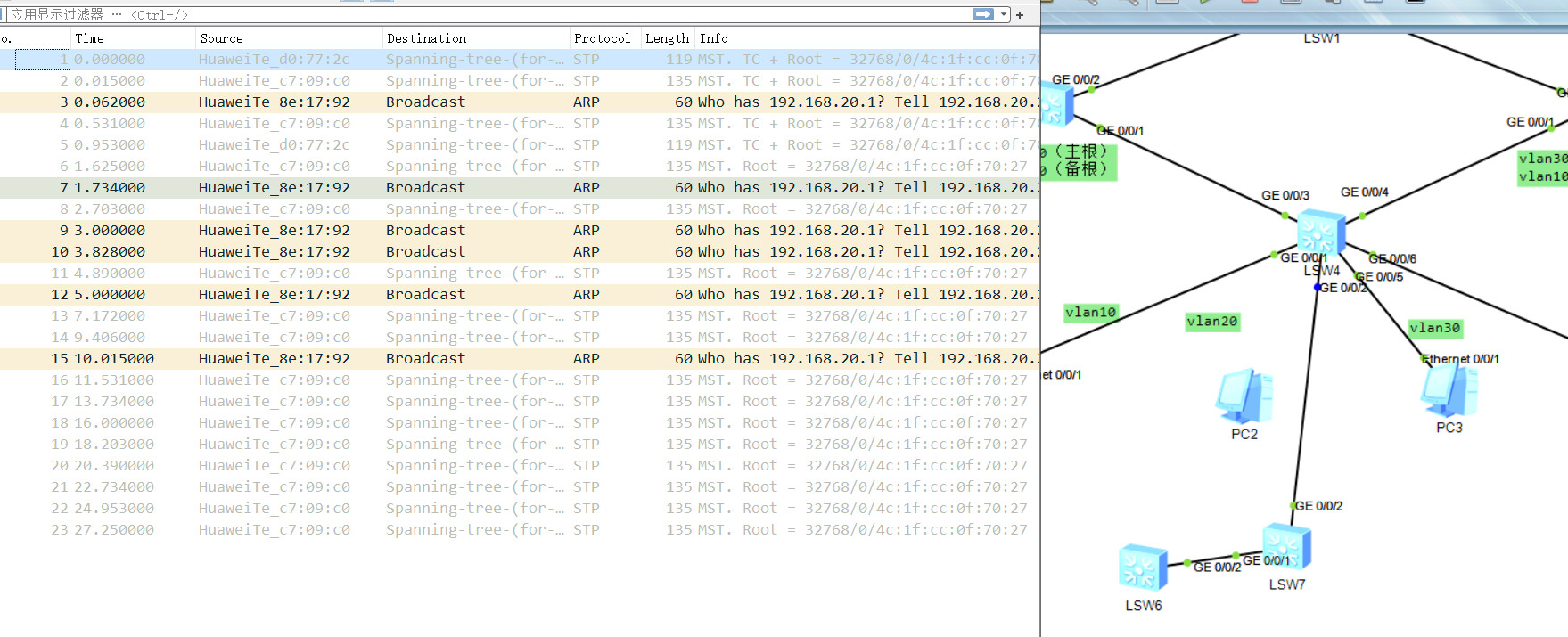
再次断开并连接, 依然是边缘端口的恢复速度:
没搞懂, 标记一个问题.
本文来自博客园,作者:Qurare,严禁转载至CSDN平台, 其他转载请注明原文链接:https://www.cnblogs.com/konjac-wjh/p/16969944.html
分类:
HCIP


【推荐】国内首个AI IDE,深度理解中文开发场景,立即下载体验Trae
【推荐】编程新体验,更懂你的AI,立即体验豆包MarsCode编程助手
【推荐】抖音旗下AI助手豆包,你的智能百科全书,全免费不限次数
【推荐】轻量又高性能的 SSH 工具 IShell:AI 加持,快人一步
· 分享一个免费、快速、无限量使用的满血 DeepSeek R1 模型,支持深度思考和联网搜索!
· 使用C#创建一个MCP客户端
· ollama系列1:轻松3步本地部署deepseek,普通电脑可用
· 基于 Docker 搭建 FRP 内网穿透开源项目(很简单哒)
· 按钮权限的设计及实现