
msm8909_LT8912B_MIPI转HDMI
项目中需要把开发板的MIPI输出信号转换为HDMI和LVDS输出,使用龙迅的LT8912B进行转换。龙迅的FAE提供的资料相对来说还是比较少的。先简单的看一下吧:
厂商资料
寄存器配置
该文件提供了对LT8912B初始化的寄存器配置。对于我们来说需要做的就是,写一个驱动,在开机的时候调用相关的函数,把对应的值写道LT8912B的寄存器里面即可。
MIPI信号要求
- MIPI信号需要关闭展频。
- MIPI的CLK不能进LP
- MIPI data 的一个采样周期不能有两个 LP
- MIPI 信号需要关闭 EOTP
https://klelee-files.oss-cn-qingdao.aliyuncs.com/LT8912B/LT8912B 输入MIPI 信号的要求.pdf
配置文档
开发记录
驱动和设备树配置
根据厂商提供的资料了解到,在开机过程中只需要把上面提到的寄存器写一遍即可,但是在这之前需要先把LT8912B reset上一下电,这个需要一个单独的GPIO去控制。
我们项目中使用LCD的reset去当MIPI的reset键。
设备树的配置
因为我们需要通过IIC去和LT8912B通讯来初始化LT8912B,所以就把reset键挂载对应的IIC总线下即可。我们项目中LT8912B使用的IIC所在的总线是i2c_2.
根据以上信息就可以进行设备树的配置了。
直接修改设备树文件:
kernel/arch/arm/boot/dts/qcom/sc806-evk/msm8909.dtsi
&i2c_2 { lt8912 { compatible = "lontium,lt8912"; reg = <0x48>; pinctrl-names = "default","sleep"; pinctrl-0 = <<_default>; pinctrl-1 = <<_sleep>; reset-gpios = <&msm_gpio 25 0x0>; }; };
kernel/arch/arm/boot/dts/qcom/sc806-evk/msm8909-pinctrl.dtsi
lt8912_reset_pin { qcom,pins = <&gp 25>; qcom,pin-func = <0>; qcom,num-grp-pins = <1>; label = "lt8912_reset_pin"; lt_default: lt_default { drive-strength = <6>; bias-pull-up; }; lt_sleep: lt_sleep { drive-strength = <2>; bias-pull-down; }; };
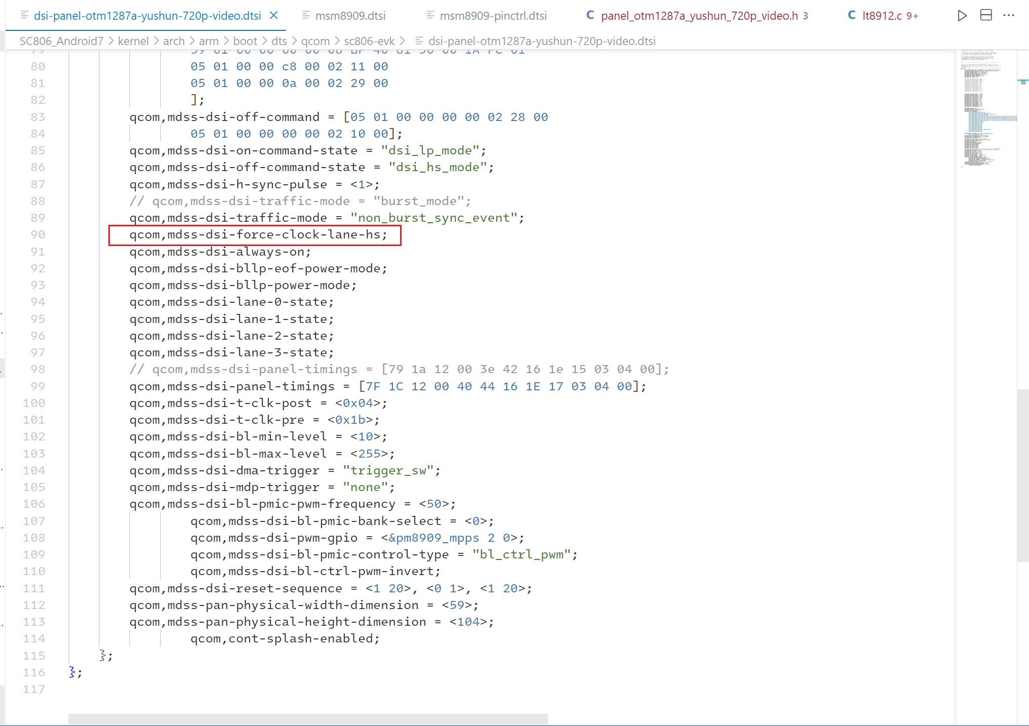
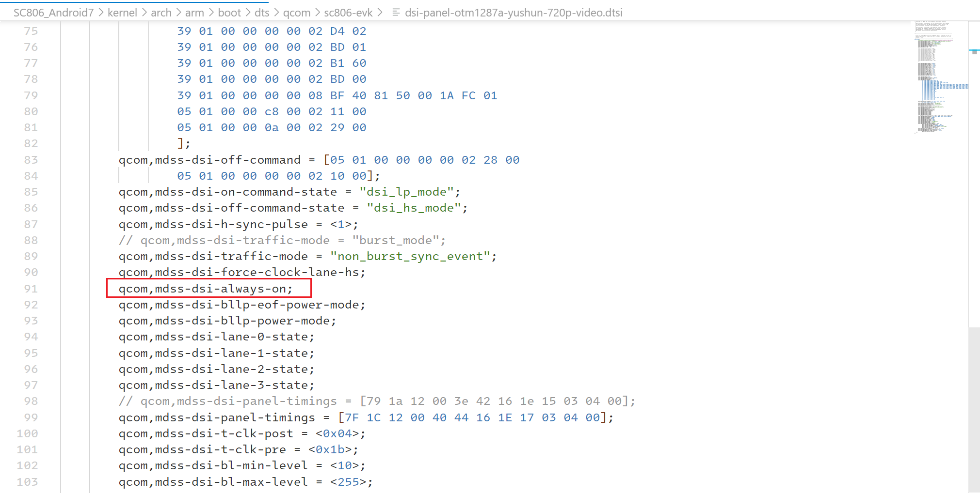
kernel/arch/arm/boot/dts/qcom/sc806-evk/dsi-panel-otm1287a-yushun-720p-video.dtsi
&mdss_mdp { dsi_otm1287a_yushun_720_vid: qcom,mdss_dsi_otm1287a_yushun_720p_video { qcom,mdss-dsi-panel-name = "OTM1287A 01 720p video mode dsi panel"; qcom,mdss-dsi-panel-controller = <&mdss_dsi0>; qcom,mdss-dsi-panel-type = "dsi_video_mode"; // 确认是video_mode qcom,mdss-dsi-panel-destination = "display_1"; qcom,mdss-dsi-panel-framerate = <60>; qcom,mdss-dsi-virtual-channel-id = <0>; qcom,mdss-dsi-stream = <0>; /* qcom,mdss-dsi-panel-width = <720>; qcom,mdss-dsi-panel-height = <1280>; qcom,mdss-dsi-h-front-porch = <52>; qcom,mdss-dsi-h-back-porch = <100>; qcom,mdss-dsi-h-pulse-width = <24>; qcom,mdss-dsi-h-sync-skew = <0>; qcom,mdss-dsi-v-back-porch = <40>; qcom,mdss-dsi-v-front-porch = <8>; qcom,mdss-dsi-v-pulse-width = <4>; qcom,mdss-dsi-h-left-border = <0>; qcom,mdss-dsi-h-right-border = <0>; qcom,mdss-dsi-v-top-border = <0>; qcom,mdss-dsi-v-bottom-border = <0>; */ /* 注释掉上面的,添加下面这些 */ qcom,mdss-dsi-panel-width = <1280>; qcom,mdss-dsi-panel-height = <720>; qcom,mdss-dsi-h-front-porch = <110>; qcom,mdss-dsi-h-back-porch = <220>; qcom,mdss-dsi-h-pulse-width = <40>; qcom,mdss-dsi-h-sync-skew = <0>; qcom,mdss-dsi-v-back-porch = <20>; qcom,mdss-dsi-v-front-porch = <5>; qcom,mdss-dsi-v-pulse-width = <5>; qcom,mdss-dsi-h-left-border = <0>; qcom,mdss-dsi-h-right-border = <0>; qcom,mdss-dsi-v-top-border = <0>; qcom,mdss-dsi-v-bottom-border = <0>; qcom,mdss-dsi-bpp = <24>; qcom,mdss-dsi-underflow-color = <0xff>; qcom,mdss-dsi-border-color = <0>; qcom,mdss-dsi-on-command = [ 39 01 00 00 00 00 04 B9 FF 83 94 39 01 00 00 00 00 07 BA 63 03 68 6B B2 C0 39 01 00 00 00 00 0B B1 48 12 72 09 32 44 71 31 4F 35 39 01 00 00 00 00 06 B2 00 80 64 05 07 39 01 00 00 00 00 1f B4 26 76 26 76 26 26 05 10 86 35 00 3F 26 76 26 76 26 26 05 10 86 3F 00 FF 81 81 81 81 08 01 39 01 00 00 00 00 22 D3 00 00 0F 0F 01 01 10 10 32 10 00 00 00 32 15 04 05 04 32 15 14 05 14 37 33 04 04 37 00 00 47 05 40 39 01 00 00 00 00 2d D5 18 18 25 24 27 26 11 10 15 14 13 12 17 16 01 00 18 18 18 18 18 18 18 18 18 18 05 04 03 02 07 06 18 18 18 18 21 20 23 22 18 18 18 18 39 01 00 00 00 00 2d D6 18 18 22 23 20 21 12 13 16 17 10 11 14 15 06 07 18 18 18 18 18 18 18 18 18 18 02 03 04 05 00 01 18 18 18 18 26 27 24 25 18 18 18 18 39 01 00 00 00 00 3b E0 00 03 0B 0E 10 13 17 15 2D 3D 51 51 5E 75 7C 84 94 9A 98 A6 B2 57 57 5A 60 64 6A 72 7F 00 03 0B 0E 10 13 17 15 2D 3D 51 51 5E 75 7C 84 94 9A 98 A6 B2 57 57 5A 60 64 6A 72 7F 39 01 00 00 00 00 03 B6 4E 4E 39 01 00 00 00 00 02 CC 0B 39 01 00 00 00 00 03 C0 1F 31 39 01 00 00 00 00 02 D2 88 39 01 00 00 00 00 02 D4 02 39 01 00 00 00 00 02 BD 01 39 01 00 00 00 00 02 B1 60 39 01 00 00 00 00 02 BD 00 39 01 00 00 00 00 08 BF 40 81 50 00 1A FC 01 05 01 00 00 c8 00 02 11 00 05 01 00 00 0a 00 02 29 00 ]; qcom,mdss-dsi-off-command = [05 01 00 00 00 00 02 28 00 05 01 00 00 00 00 02 10 00]; qcom,mdss-dsi-on-command-state = "dsi_lp_mode"; qcom,mdss-dsi-off-command-state = "dsi_hs_mode"; qcom,mdss-dsi-h-sync-pulse = <1>; // qcom,mdss-dsi-traffic-mode = "burst_mode"; qcom,mdss-dsi-traffic-mode = "non_burst_sync_event"; // 修改为:non_burst_sync_event qcom,mdss-dsi-force-clock-lane-hs; // 添加这行 qcom,mdss-dsi-always-on; // 添加这行 qcom,mdss-dsi-bllp-eof-power-mode; qcom,mdss-dsi-bllp-power-mode; qcom,mdss-dsi-lane-0-state; qcom,mdss-dsi-lane-1-state; qcom,mdss-dsi-lane-2-state; qcom,mdss-dsi-lane-3-state; // qcom,mdss-dsi-panel-timings = [79 1a 12 00 3e 42 16 1e 15 03 04 00]; qcom,mdss-dsi-panel-timings = [7F 1C 12 00 40 44 16 1E 17 03 04 00]; // 修改 qcom,mdss-dsi-t-clk-post = <0x04>; qcom,mdss-dsi-t-clk-pre = <0x1b>; qcom,mdss-dsi-bl-min-level = <10>; qcom,mdss-dsi-bl-max-level = <255>; qcom,mdss-dsi-dma-trigger = "trigger_sw"; qcom,mdss-dsi-mdp-trigger = "none"; qcom,mdss-dsi-bl-pmic-pwm-frequency = <50>; qcom,mdss-dsi-bl-pmic-bank-select = <0>; qcom,mdss-dsi-pwm-gpio = <&pm8909_mpps 2 0>; qcom,mdss-dsi-bl-pmic-control-type = "bl_ctrl_pwm"; qcom,mdss-dsi-bl-ctrl-pwm-invert; qcom,mdss-dsi-reset-sequence = <1 20>, <0 1>, <1 20>; qcom,mdss-pan-physical-width-dimension = <59>; qcom,mdss-pan-physical-height-dimension = <104>; qcom,cont-splash-enabled; }; };
驱动编写
遇到的坑后面说,这里先贴驱动代码。
kernel/drivers/video/msm/mdss/lt8912.c
#include <linux/init.h> #include <linux/i2c.h> #include <linux/module.h> #include <linux/kernel.h> #include <linux/device.h> #include <linux/platform_device.h> #include <linux/of.h> #include <linux/of_device.h> #include <linux/irqreturn.h> #include <linux/kd.h> #include <linux/sched.h> #include <linux/slab.h> #include <linux/delay.h> #include <linux/gpio.h> #include <linux/of_gpio.h> #include <linux/errno.h> #include <linux/input.h> #include <linux/serio.h> #include <linux/clk.h> #include <linux/io.h> #include <asm/irq.h> #include <linux/timer.h> #include <linux/workqueue.h> #include <linux/jiffies.h> #include <linux/hrtimer.h> #include <linux/workqueue.h> #include <linux/regulator/consumer.h> #include <linux/debugfs.h> #include <linux/proc_fs.h> #include <linux/kthread.h> #include <linux/regmap.h> #include <linux/pm_runtime.h> #include "lt8912.h" #define MIPI_1080P #define device_name "lt8912" /*****************************************************************************************/ /* lt8912 相关参数配置 */ uint8_t I2CADR; #define _HDMI_Output_ #define _LVDS_Output_ enum { H_act = 0, V_act, H_tol, V_tol, H_bp, H_sync, V_sync, V_bp }; #ifdef _HDMI_Output_ enum { _32KHz = 0, _44d1KHz, _48KHz, _88d2KHz, _96KHz, _176Khz, _196KHz }; uint16_t IIS_N[] = { 4096, // 32K 6272, // 44.1K 6144, // 48K 12544, // 88.2K 12288, // 96K 25088, // 176K 24576 // 196K }; uint16_t Sample_Freq[] = { 0x30, // 32K 0x00, // 44.1K 0x20, // 48K 0x80, // 88.2K 0xa0, // 96K 0xc0, // 176K 0xe0 // 196K }; #endif // _HDMI_Output_ #ifdef _LVDS_Output_ /* 设置输出模式,ByPass模式,MIPI输出多大,LVDS就输出多大;Scaler模式,可以调整缩放比例 */ #define _Bypass_Mode_ // #define _Scaler_Mode_ /* 设置色深 */ #define _8_Bit_Color_ // 24 bit // #define _6_Bit_Color_ // 18 bit /* 定义LVDS输出模式 */ #define _VESA_ // #define _JEIDA_ // #define _De_mode_ // only DE #define _Sync_Mode_ // Hsync + Vsync + DE /***Output sync mode sync polarity***/ #define _Hsync_polarity_active_high 0x02 // default, POSITIVE #define _Hsync_polarity_active_low 0x00 // NEGATIVE #define _Vsync_polarity_active_high 0x01 // default, POSITIVE #define _Vsync_polarity_active_low 0x00 // NEGATIVE #define _Hsync_polarity _Hsync_polarity_active_high #define _Vsync_polarity _Vsync_polarity_active_high #define _VesaJeidaMode 0x00 #define _DE_Sync_mode 0x00 #ifdef _VESA_ #define _VesaJeidaMode 0x00 #else #define _VesaJeidaMode 0x20 #endif // _VESA_ #ifdef _De_mode_ #define _DE_Sync_mode 0x08 #else #define _DE_Sync_mode 0x00 #endif // _De_mode_ #ifdef _8_Bit_Color_ #define _ColorDeepth 0x10 #else #define _ColorDeepth 0x14 #endif // _8_Bit_Color_ #endif // _LVDS_Output_ #ifdef _HDMI_Output_ u8 AVI_PB0 = 0x00; u8 AVI_PB1 = 0x00; u8 AVI_PB2 = 0x00; /* Resolution HDMI_VIC -------------------------------------- 640x480 1 720x480P 60Hz 2 720x480i 60Hz 6 720x576P 50Hz 17 720x576i 50Hz 21 1280x720P 24Hz 60 1280x720P 25Hz 61 1280x720P 30Hz 62 1280x720P 50Hz 19 1280x720P 60Hz 4 1920x1080P 24Hz 32 1920x1080P 25Hz 33 1920x1080P 30Hz 34 1920x1080i 50Hz 20 1920x1080i 60Hz 5 1920x1080P 50Hz 31 1920x1080P 60Hz 16 3840x2160 30Hz 95 // 4K30 Other resolution 0(default) */ u8 HDMI_VIC = 0x00; #endif // _HDMI_Output_ /*****************************************************************************************/ /* MIPI 输入信号配置 */ #define MIPI_Lane 4 // 根据前端MIPI输入信号的Timing修改以下宏定义的值: #define MIPI_H_Active 1280 #define MIPI_V_Active 720 #define MIPI_H_Total 1650 #define MIPI_V_Total 750 #define MIPI_H_FrontPorch 110 #define MIPI_H_SyncWidth 40 #define MIPI_H_BackPorch 220 #define MIPI_V_FrontPorch 5 #define MIPI_V_SyncWidth 5 #define MIPI_V_BackPorch 20 u8 MIPI_Lane_CH_Swap = 0x00;// 00: 0123 normal ; a8 : 3210 swap #define _PN_Swap_En 0x20 #define _PN_Swap_Dis 0x00 u8 MIPI_Lane_PN_Swap = _PN_Swap_Dis ; /* VESA配置 */ #define VESA_720x480_60 0 #define VESA_1280x720_60 (VESA_720x480_60+1) #define VESA_1280x800_60 (VESA_1280x720_60+1) #define VESA_1024x600_60 (VESA_1280x800_60+1) #define VESA_1920x1080_60 (VESA_1024x600_60+1) struct lt8912_data { struct i2c_client *lt8912_client; struct regmap *regmap; struct input_dev *input_hotplug; struct delayed_work hotplug_work; int reset_gpio; int last_val; }; struct lt8912_data *lt; /*****************************************************************************************/ /* LT8912 操作函数开始 */ static int lt8912_i2c_write_byte(uint8_t reg, uint8_t val) { int ret = 0; if (!lt) { printk("dsi0 xxxx%s: Invalid argument\n", __func__); return -EINVAL; } lt->lt8912_client->addr = I2CADR >> 1; ret = i2c_smbus_write_byte_data(lt->lt8912_client, reg, val); if (ret) pr_err_ratelimited("%s: wr err: addr 0x%x, reg 0x%x, val 0x%x\n", __func__, I2CADR, reg, val); return ret; } static int lt8912_i2c_read_byte(uint8_t reg) { int ret = 0; if (!lt) { printk("dsi0 xxxx%s: Invalid argument\n", __func__); return -EINVAL; } lt->lt8912_client->addr = I2CADR >> 1; ret = i2c_smbus_read_byte_data(lt->lt8912_client, reg); if (ret < 0) { printk("failed to read byte lt index=%d\n", reg); return -1; } else { printk("Like: Read Reg [%02X][%02X]\n", reg, ret); } return 0; } void MIPI_Digital(void) { I2CADR = 0x92; lt8912_i2c_write_byte( 0x18, (u8)( MIPI_H_SyncWidth % 256 ) ); // hwidth lt8912_i2c_write_byte( 0x19, (u8)( MIPI_V_SyncWidth % 256 ) ); // vwidth lt8912_i2c_write_byte( 0x1c, (u8)( MIPI_H_Active % 256 ) ); // H_active[7:0] lt8912_i2c_write_byte( 0x1d, (u8)( MIPI_H_Active / 256 ) ); // H_active[15:8] lt8912_i2c_write_byte( 0x1e, 0x67 ); lt8912_i2c_write_byte( 0x2f, 0x0c ); lt8912_i2c_write_byte( 0x34, (u8)( MIPI_H_Total % 256 ) ); // H_total[7:0] lt8912_i2c_write_byte( 0x35, (u8)( MIPI_H_Total / 256 ) ); // H_total[15:8] lt8912_i2c_write_byte( 0x36, (u8)( MIPI_V_Total % 256 ) ); // V_total[7:0] lt8912_i2c_write_byte( 0x37, (u8)( MIPI_V_Total / 256 ) ); // V_total[15:8] lt8912_i2c_write_byte( 0x38, (u8)( MIPI_V_BackPorch % 256 ) ); // VBP[7:0] lt8912_i2c_write_byte( 0x39, (u8)( MIPI_V_BackPorch / 256 ) ); // VBP[15:8] lt8912_i2c_write_byte( 0x3a, (u8)( MIPI_V_FrontPorch % 256 ) ); // VFP[7:0] lt8912_i2c_write_byte( 0x3b, (u8)( MIPI_V_FrontPorch / 256 ) ); // VFP[15:8] lt8912_i2c_write_byte( 0x3c, (u8)( MIPI_H_BackPorch % 256 ) ); // HBP[7:0] lt8912_i2c_write_byte( 0x3d, (u8)( MIPI_H_BackPorch / 256 ) ); // HBP[15:8] lt8912_i2c_write_byte( 0x3e, (u8)( MIPI_H_FrontPorch % 256 ) ); // HFP[7:0] lt8912_i2c_write_byte( 0x3f, (u8)( MIPI_H_FrontPorch / 256 ) ); // HFP[15:8] } /*********************************************************** ***********************************************************/ void DDS_Config(void) { I2CADR = 0x92; lt8912_i2c_write_byte( 0x4e, 0x52 ); lt8912_i2c_write_byte( 0x4f, 0xde ); lt8912_i2c_write_byte( 0x50, 0xc0 ); lt8912_i2c_write_byte( 0x51, 0x80 ); // lt8912_i2c_write_byte( 0x51, 0x00 ); lt8912_i2c_write_byte( 0x1e, 0x4f ); lt8912_i2c_write_byte( 0x1f, 0x5e ); lt8912_i2c_write_byte( 0x20, 0x01 ); lt8912_i2c_write_byte( 0x21, 0x2c ); lt8912_i2c_write_byte( 0x22, 0x01 ); lt8912_i2c_write_byte( 0x23, 0xfa ); lt8912_i2c_write_byte( 0x24, 0x00 ); lt8912_i2c_write_byte( 0x25, 0xc8 ); lt8912_i2c_write_byte( 0x26, 0x00 ); lt8912_i2c_write_byte( 0x27, 0x5e ); lt8912_i2c_write_byte( 0x28, 0x01 ); lt8912_i2c_write_byte( 0x29, 0x2c ); lt8912_i2c_write_byte( 0x2a, 0x01 ); lt8912_i2c_write_byte( 0x2b, 0xfa ); lt8912_i2c_write_byte( 0x2c, 0x00 ); lt8912_i2c_write_byte( 0x2d, 0xc8 ); lt8912_i2c_write_byte( 0x2e, 0x00 ); lt8912_i2c_write_byte( 0x42, 0x64 ); lt8912_i2c_write_byte( 0x43, 0x00 ); lt8912_i2c_write_byte( 0x44, 0x04 ); lt8912_i2c_write_byte( 0x45, 0x00 ); lt8912_i2c_write_byte( 0x46, 0x59 ); lt8912_i2c_write_byte( 0x47, 0x00 ); lt8912_i2c_write_byte( 0x48, 0xf2 ); lt8912_i2c_write_byte( 0x49, 0x06 ); lt8912_i2c_write_byte( 0x4a, 0x00 ); lt8912_i2c_write_byte( 0x4b, 0x72 ); lt8912_i2c_write_byte( 0x4c, 0x45 ); lt8912_i2c_write_byte( 0x4d, 0x00 ); lt8912_i2c_write_byte( 0x52, 0x08 ); lt8912_i2c_write_byte( 0x53, 0x00 ); lt8912_i2c_write_byte( 0x54, 0xb2 ); lt8912_i2c_write_byte( 0x55, 0x00 ); lt8912_i2c_write_byte( 0x56, 0xe4 ); lt8912_i2c_write_byte( 0x57, 0x0d ); lt8912_i2c_write_byte( 0x58, 0x00 ); lt8912_i2c_write_byte( 0x59, 0xe4 ); lt8912_i2c_write_byte( 0x5a, 0x8a ); lt8912_i2c_write_byte( 0x5b, 0x00 ); lt8912_i2c_write_byte( 0x5c, 0x34 ); lt8912_i2c_write_byte( 0x51, 0x00 ); } #ifdef _HDMI_Output_ void Audio_Config(void) { // Audio config I2CADR = 0x90; lt8912_i2c_write_byte( 0xB2, 0x01 ); // 0x01:HDMI; 0x00: DVI I2CADR = 0x94; lt8912_i2c_write_byte( 0x06, 0x08 ); // 0x09 lt8912_i2c_write_byte( 0x07, 0xF0 ); // enable Audio: 0xF0; Audio Mute: 0x00 lt8912_i2c_write_byte( 0x09, 0x00 ); // 0x00:Left justified; default lt8912_i2c_write_byte( 0x0f, 0x0b + Sample_Freq[_48KHz] ); lt8912_i2c_write_byte( 0x37, (u8)( IIS_N[_48KHz] / 0x10000 ) ); lt8912_i2c_write_byte( 0x36, (u8)( ( IIS_N[_48KHz] & 0x00FFFF ) / 0x100 ) ); lt8912_i2c_write_byte( 0x35, (u8)( IIS_N[_48KHz] & 0x0000FF ) ); lt8912_i2c_write_byte( 0x34, 0xD2 ); // 32 bit的数据长度 // lt8912_i2c_write_byte( 0x34, 0xE2 ); // 16 bit的数据长度 lt8912_i2c_write_byte( 0x3c, 0x41 ); // Null packet enable } void AVI_Config(void) { I2CADR = 0x94; lt8912_i2c_write_byte( 0x3e, 0x0A ); // 0x43寄存器是checksums,改变了0x45或者0x47 寄存器的值,0x43寄存器的值也要跟着变, // 0x43,0x44,0x45,0x47四个寄存器值的总和是0x6F HDMI_VIC = 0x04; // 720P 60; Corresponding to the resolution to be output // HDMI_VIC = 0x10; // 1080P 60 // HDMI_VIC = 0x1F; // 1080P 50 // HDMI_VIC = 0x00; // If the resolution is non-standard, set to 0x00 AVI_PB1 = 0x10; // PB1,color space: YUV444 0x70;YUV422 0x30; RGB 0x10 AVI_PB2 = 0x2A; // PB2; picture aspect rate: 0x19:4:3 ; 0x2A : 16:9 AVI_PB0 = ( ( AVI_PB1 + AVI_PB2 + HDMI_VIC ) <= 0x6f ) ? ( 0x6f - AVI_PB1 - AVI_PB2 - HDMI_VIC ) : ( 0x16f - AVI_PB1 - AVI_PB2 - HDMI_VIC ); lt8912_i2c_write_byte( 0x43, AVI_PB0 ); //avi packet checksum ,avi_pb0 lt8912_i2c_write_byte( 0x44, AVI_PB1 ); //avi packet output RGB 0x10 lt8912_i2c_write_byte( 0x45, AVI_PB2 ); //0x19:4:3 ; 0x2A : 16:9 lt8912_i2c_write_byte( 0x47, HDMI_VIC ); //VIC(as below);1080P60 : 0x10 } #endif #ifdef _Bypass_Mode_ void LVDS_Bypass_Config(void) { //lvds power up I2CADR = 0x90; //0x90; //lt8912_i2c_write_byte( 0x51, 0x05 ); //core pll bypass lt8912_i2c_write_byte( 0x50, 0x24 ); //cp=50uA lt8912_i2c_write_byte( 0x51, 0x2d ); //Pix_clk as reference,second order passive LPF PLL lt8912_i2c_write_byte( 0x52, 0x04 ); //loopdiv=0;use second-order PLL //PLL CLK lt8912_i2c_write_byte( 0x69, 0x0e ); lt8912_i2c_write_byte( 0x69, 0x8e ); lt8912_i2c_write_byte( 0x6a, 0x00 ); lt8912_i2c_write_byte( 0x6c, 0xb8 ); lt8912_i2c_write_byte( 0x6b, 0x51 ); lt8912_i2c_write_byte( 0x04, 0xfb ); //core pll reset lt8912_i2c_write_byte( 0x04, 0xff ); //scaler bypass lt8912_i2c_write_byte( 0x7f, 0x00 ); lt8912_i2c_write_byte( 0xa8, _VesaJeidaMode + _DE_Sync_mode + _ColorDeepth + _Hsync_polarity + _Vsync_polarity); msleep( 100 ); lt8912_i2c_write_byte( 0x02, 0xf7 ); //lvds pll reset lt8912_i2c_write_byte( 0x02, 0xff ); lt8912_i2c_write_byte( 0x03, 0xcb ); //scaler module reset lt8912_i2c_write_byte( 0x03, 0xfb ); //lvds tx module reset lt8912_i2c_write_byte( 0x03, 0xff ); } #endif void lt8912_reset(void) { gpio_direction_output(lt->reset_gpio, 0); msleep(100); gpio_direction_output(lt->reset_gpio, 1); msleep(100); } void lt8912_read_test(void) { // video check lt8912_i2c_read_byte( 0x9c ); lt8912_i2c_read_byte( 0x9d ); lt8912_i2c_read_byte( 0x9e ); lt8912_i2c_read_byte( 0x9f ); // pixel clock lt8912_i2c_read_byte( 0x0c ); lt8912_i2c_read_byte( 0x0d ); lt8912_i2c_read_byte( 0x0e ); lt8912_i2c_read_byte( 0x0f ); // mipi lane lt8912_i2c_read_byte( 0x13 ); // lane swap lt8912_i2c_read_byte( 0x15 ); } void lt8912_start(void) { lt8912_reset(); I2CADR = 0x90; // IIC address /* LVDS 配置 */ lt8912_i2c_write_byte( 0x08, 0xff ); // Register address : 0x08; Value : 0xff lt8912_i2c_write_byte( 0x09, 0xff ); lt8912_i2c_write_byte( 0x0a, 0xff ); lt8912_i2c_write_byte( 0x0b, 0x7c ); // lt8912_i2c_write_byte( 0x0c, 0xff ); lt8912_i2c_write_byte( 0x51, 0x15 ); I2CADR = 0x90; lt8912_i2c_write_byte( 0x31, 0xa1 ); lt8912_i2c_write_byte( 0x32, 0xbf ); lt8912_i2c_write_byte( 0x33, 0x17 ); // bit0/bit1 =1 Turn On HDMI Tx; bit0/bit1 = 0 Turn Off HDMI Tx lt8912_i2c_write_byte( 0x37, 0x00 ); lt8912_i2c_write_byte( 0x38, 0x22 ); lt8912_i2c_write_byte( 0x60, 0x82 ); I2CADR = 0x90; lt8912_i2c_write_byte( 0x39, 0x45 ); lt8912_i2c_write_byte( 0x3a, 0x00 ); lt8912_i2c_write_byte( 0x3b, 0x00 ); I2CADR = 0x90; lt8912_i2c_write_byte( 0x3e, 0x96 + MIPI_Lane_PN_Swap ); // lt8912_i2c_write_byte( 0x41, 0x7c ); //HS_eq current I2CADR = 0x90; lt8912_i2c_write_byte( 0x44, 0x31 ); lt8912_i2c_write_byte( 0x55, 0x44 ); lt8912_i2c_write_byte( 0x57, 0x01 ); lt8912_i2c_write_byte( 0x5a, 0x02 ); I2CADR = 0x92; lt8912_i2c_write_byte( 0x10, 0x01 ); // 0x05 lt8912_i2c_write_byte( 0x11, 0x08 ); // 0x12 lt8912_i2c_write_byte( 0x12, 0x04 ); lt8912_i2c_write_byte( 0x13, MIPI_Lane % 0x04 ); // 00 4 lane // 01 lane // 02 2lane //03 3 lane lt8912_i2c_write_byte( 0x14, 0x00 ); lt8912_i2c_write_byte( 0x15, MIPI_Lane_CH_Swap ); // 00: 0123 normal ; a8 : 3210 swap lt8912_i2c_write_byte( 0x1a, 0x03 ); lt8912_i2c_write_byte( 0x1b, 0x03 ); // 设置 MIPI Timing MIPI_Digital(); DDS_Config(); #ifdef _HDMI_Output_ Audio_Config(); AVI_Config(); #endif I2CADR = 0x90; lt8912_i2c_write_byte( 0x03, 0x7f ); // mipi rx reset msleep( 10 ); lt8912_i2c_write_byte( 0x03, 0xff ); lt8912_i2c_write_byte( 0x05, 0xfb ); // DDS reset msleep( 10 ); lt8912_i2c_write_byte( 0x05, 0xff ); #ifdef _LVDS_Output_ #ifdef _Bypass_Mode_ LVDS_Bypass_Config(); #endif I2CADR = 0x90; lt8912_i2c_write_byte( 0x44, 0x30 ); // Turn on LVDS output #endif I2CADR = 0x90; // IIC address lt8912_read_test(); } EXPORT_SYMBOL_GPL(lt8912_start); /*****************************************************************************************/ static const struct of_device_id of_lt8912_match[] = { { .compatible = "lontium,lt8912",}, {}, }; static const struct i2c_device_id lt8912_id[] = { {device_name, 0}, {} }; MODULE_DEVICE_TABLE(i2c, lt8912_id); static int lt8912_parse_dt(struct device *dev) { struct device_node *np = dev->of_node; lt->reset_gpio = of_get_named_gpio(np, "reset-gpios", 0); printk("lt8912_reset_gpio number: %d\n", lt->reset_gpio); if (lt->reset_gpio < 0) return lt->reset_gpio; return 0; } static int lontium_i2c_probe(struct i2c_client *client, const struct i2c_device_id *id) { int ret = 0; printk("Like: %s enter!\n", __func__); if (!i2c_check_functionality(client->adapter, I2C_FUNC_I2C)) { dev_err(&client->dev, "lt8912 i2c check failed.\n"); return -ENODEV; } lt = devm_kzalloc(&client->dev, sizeof(struct lt8912_data), GFP_KERNEL); lt->lt8912_client = client; if (client->dev.of_node) { ret = lt8912_parse_dt(&client->dev); if (ret) { printk("Like: lt8912_parse_dt failed!\n"); goto out; } } else { printk("Like: lt8912 device tree is failed!\n"); ret = -ENODEV; goto out; } dev_set_drvdata(&client->dev, lt); if (gpio_is_valid(lt->reset_gpio)) { ret = gpio_request(lt->reset_gpio, "lt8912_reset_gpio"); if (ret) { printk("Like: reset gpio request failed!\n"); goto out; } printk("Like: enter gpio_request!\n"); ret = gpio_direction_output(lt->reset_gpio, 0); if (ret) { printk("set_direction for reset gpio failed\n"); goto free_reset_gpio; } msleep(20); gpio_set_value_cansleep(lt->reset_gpio, 1); printk("Like: enter gpio_set_value_cansleep\n"); } lt8912_start(); pm_runtime_enable(&client->dev); pm_runtime_set_active(&client->dev); free_reset_gpio: if (gpio_is_valid(lt->reset_gpio)) gpio_free(lt->reset_gpio); out: printk("Like: lt8912_probe exit...\n"); return ret; } static int lontium_i2c_remove(struct i2c_client *client) { lt = dev_get_drvdata(&client->dev); pm_runtime_disable(&client->dev); if (gpio_is_valid(lt->reset_gpio)) gpio_free(lt->reset_gpio); return 0; } static int lt8912_suspend(struct device *tdev) { printk("Like: lt8912 will suspend!\n"); // gpio_set_value(lt->reset_gpio, 0); return 0; } static int lt8912_resume(struct device *tdev) { printk("Like: Will restart lt8912!\n"); lt8912_start(); return 0; } static const struct dev_pm_ops lt8912_pm_ops = { .suspend = lt8912_suspend, .resume = lt8912_resume, }; static struct i2c_driver lontium_i2c_driver = { .driver = { .name = "lt8912", .owner = THIS_MODULE, .of_match_table = of_lt8912_match, .pm = <8912_pm_ops, }, .probe = lontium_i2c_probe, .remove = lontium_i2c_remove, .id_table = lt8912_id, }; static int __init lontium_i2c_test_init(void) { int ret; printk("Like: lt8912b driver enter!\n"); ret = i2c_add_driver(&lontium_i2c_driver); return ret; } static void __exit lontium_i2c_test_exit(void) { printk("Like: lt8912b driver exit!\n"); i2c_del_driver(&lontium_i2c_driver); } module_init(lontium_i2c_test_init); module_exit(lontium_i2c_test_exit); MODULE_AUTHOR("like <like@aucma.com.cn>"); MODULE_LICENSE("GPL"); MODULE_DESCRIPTION("LT8912 MIPI·DSI to HDMI and LVDS");
LK配置
Kernel阶段对屏的选择来自LK,所以LK的配置也是必要的。
panel配置
分辨率修改
bootable/bootloader/lk/dev/gcdb/display/include/panel_otm1287a_yushun_720p_video.h
static struct panel_resolution otm1287a_yushun_720p_video_panel_res = { // 720, 1280, 52, 100, 24, 0, 8, 40, 4, 0, 0, 0, 0, 0, 0, 0, 0, 0 1280, 720, 110, 220, 40, 0, 5, 20, 5, 0, 0, 0, 0, 0, 0, 0, 0, 0 };
timings修改
bootloader/lk/dev/gcdb/display/include/panel_otm1287a_yushun_720p_video.h
static const uint32_t otm1287a_yushun_720p_video_timings[] = { // 0x79 ,0x1a ,0x12 ,0x00 ,0x3e ,0x42 ,0x16 ,0x1e ,0x15 ,0x03 ,0x04 ,0x00 0x7F, 0x1c, 0x12, 0x00, 0x40, 0x44, 0x16, 0x1e, 0x17, 0x03, 0x04, 0x00 };
lane配置
bootloader/lk/dev/gcdb/display/include/panel_otm1287a_yushun_720p_video.h
static struct lane_configuration otm1287a_yushun_720p_video_lane_config = { 4, 0, 1, 1, 1, 1, 1 // 多加一个1 };
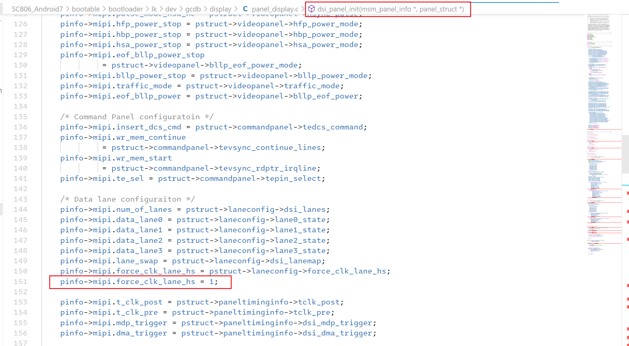
强制CLK使用HS模式
bootable/bootloader/lk/dev/gcdb/display/panel_display.c
/* Data lane configuraiton */ pinfo->mipi.num_of_lanes = pstruct->laneconfig->dsi_lanes; pinfo->mipi.data_lane0 = pstruct->laneconfig->lane0_state; pinfo->mipi.data_lane1 = pstruct->laneconfig->lane1_state; pinfo->mipi.data_lane2 = pstruct->laneconfig->lane2_state; pinfo->mipi.data_lane3 = pstruct->laneconfig->lane3_state; pinfo->mipi.lane_swap = pstruct->laneconfig->dsi_lanemap; pinfo->mipi.force_clk_lane_hs = pstruct->laneconfig->force_clk_lane_hs; // 删不删都行 pinfo->mipi.force_clk_lane_hs = 1; // 添加这行
其实要写的代码很少,要做的配置也不多,但是MIPI转HDMI这件事情整整调了一个月。其中不乏硬件挖的坑、厂商驱动给你挖的坑,下面我一一道来,没兴趣的到这里已经下课了。
遇到的坑
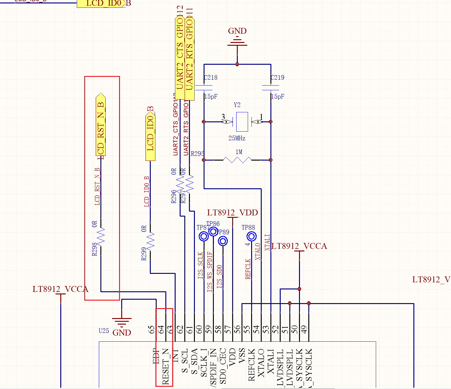
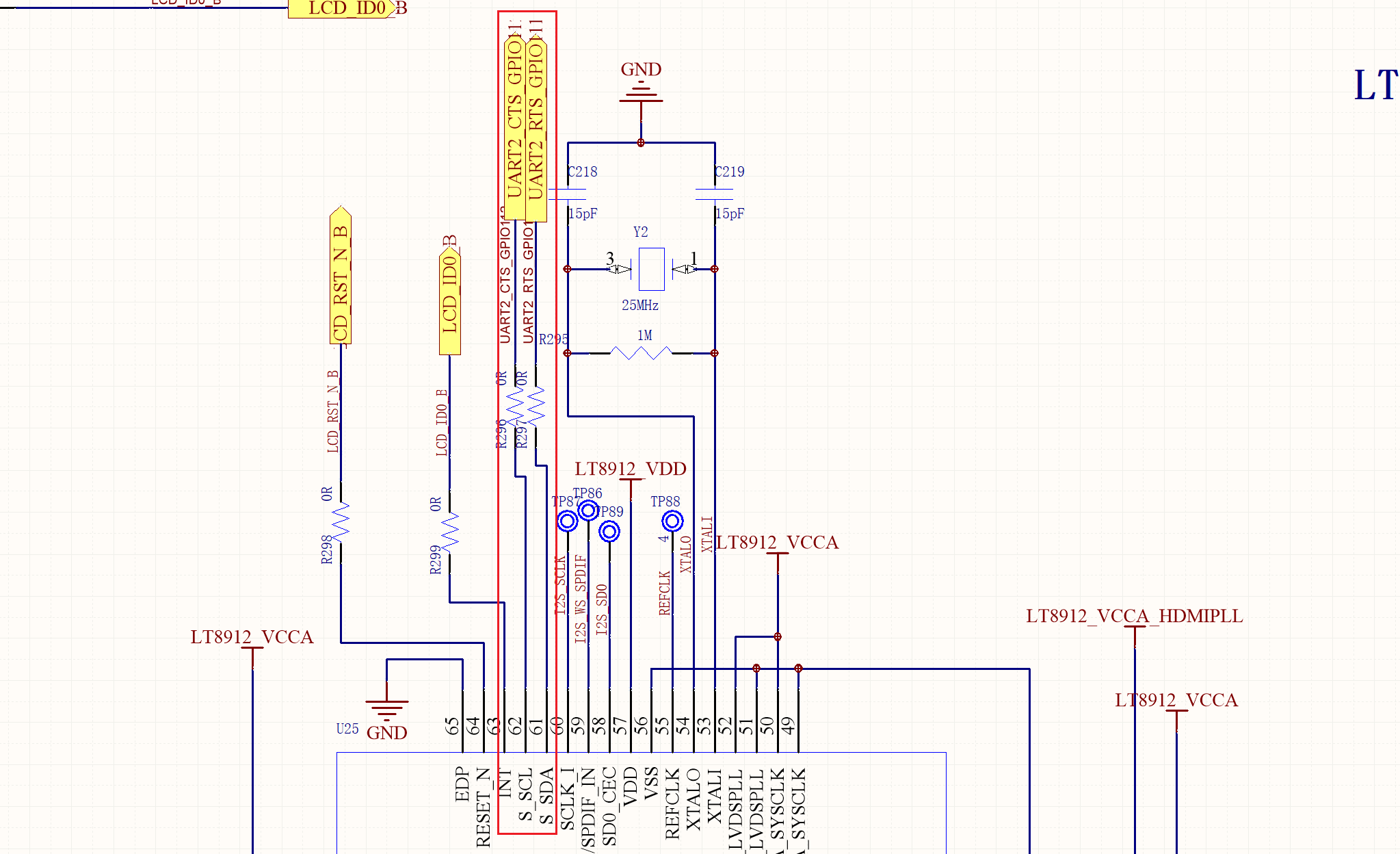
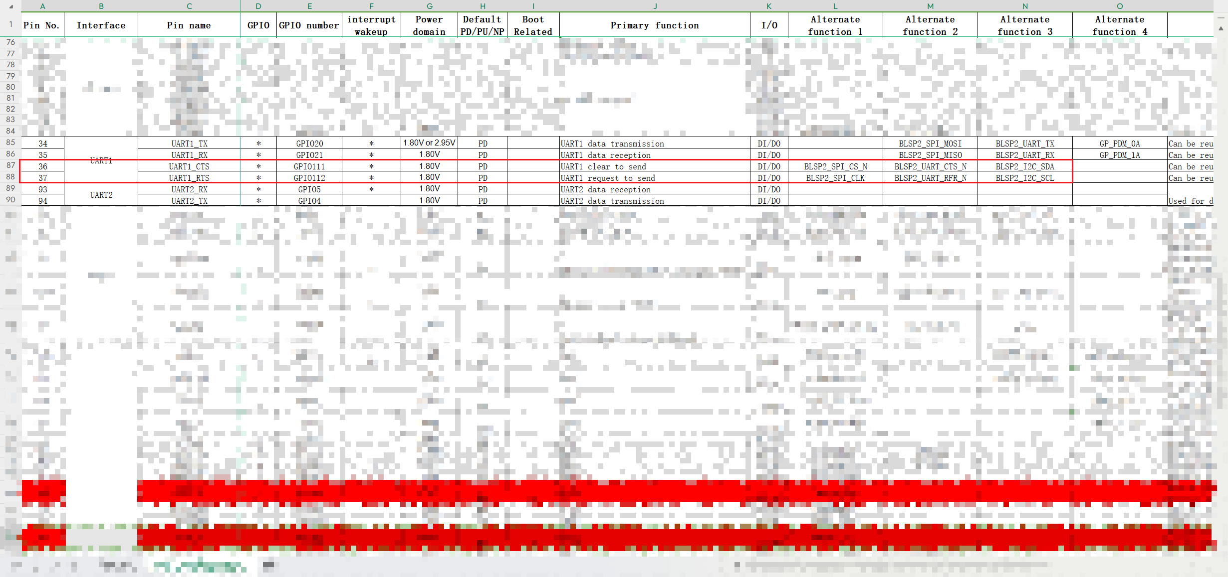
一号坑:IIC不通
形似下面这样的log
i2c-msm-v2 78b6000.i2c: NACK: slave not responding, ensure its powered: msgs(n:1 cur:0 tx) bc(rx:0 tx:2) mode:FIFO slv_addr:0x48 MSTR_STS:0x011363c8 OPER:0x00000090
结论:IIC的SDK和SCL接反了。结束
二号坑:MIPI CLK不连续
形似这样子的CLK,就是龙迅说的会进LP。对屏幕造成的最直接的现象就是屏幕会不断的刷新。哗哗的。
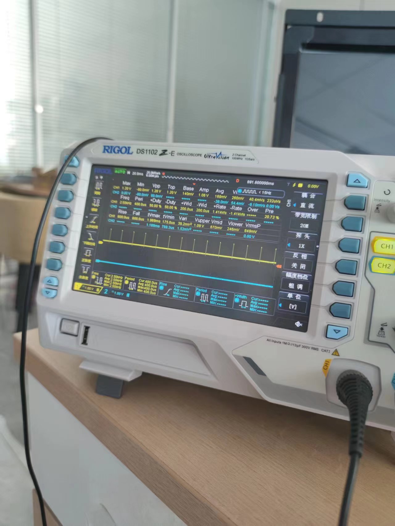
一定要首先确保CLK在LK里面是连续的。
然后是kernel里面要连续:
可以先只改这两处,别的地方包括驱动都不要写,先确保CLK是连续的,类似于正弦波。(我们的示波器不太行,这里就不插图片了)
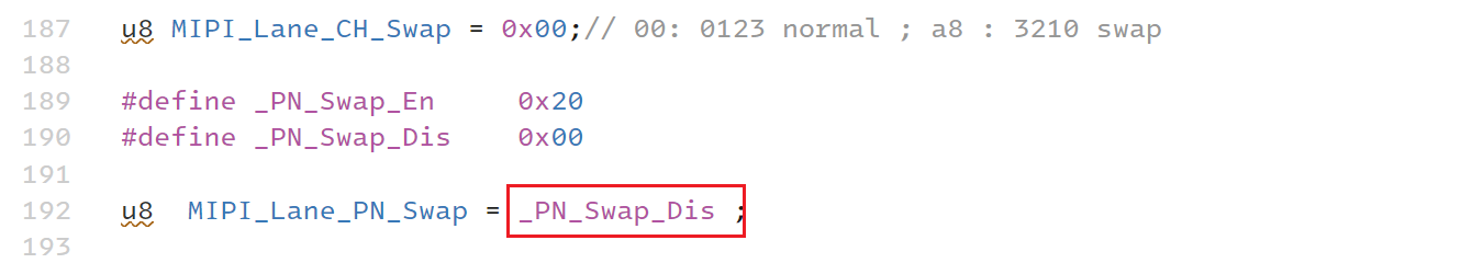
三号坑:HDMI不亮了
在CLK调好之后发现HDMI突然不亮了!!!这个时候真的一点头绪都没有,就去看原理图,意外发现原理图中PN没有反接,但我记得驱动里面似乎swap_en了!!!
所以解决方案是:_PN_Swap_Dis
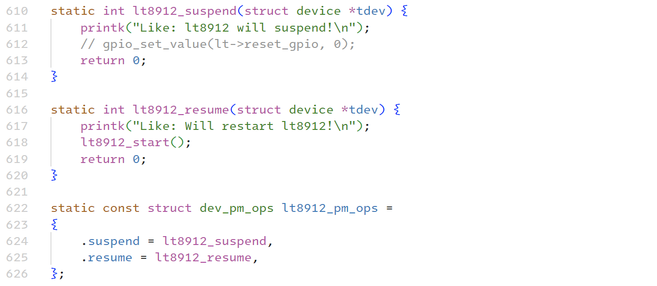
四号坑:休眠唤醒之后不亮
休眠唤醒之后需要重新初始化LT8912B
另外,dtsi也需要配置:
到这里,我的HDMI就很正常的显示啦,还有什么问题再记录吧。


【推荐】编程新体验,更懂你的AI,立即体验豆包MarsCode编程助手
【推荐】凌霞软件回馈社区,博客园 & 1Panel & Halo 联合会员上线
【推荐】抖音旗下AI助手豆包,你的智能百科全书,全免费不限次数
【推荐】博客园社区专享云产品让利特惠,阿里云新客6.5折上折
【推荐】轻量又高性能的 SSH 工具 IShell:AI 加持,快人一步
· 一个费力不讨好的项目,让我损失了近一半的绩效!
· 实操Deepseek接入个人知识库
· CSnakes vs Python.NET:高效嵌入与灵活互通的跨语言方案对比
· 【.NET】调用本地 Deepseek 模型
· Plotly.NET 一个为 .NET 打造的强大开源交互式图表库