
私有云POC用户指南
1.5 Constraints and Assumptions 1
2 High-Level POC Architecture 3
3.1 Sequence Diagram for Iaas & SaaS 4
4.1 Server Physical Infrastructure 6
Server Physical Machine Table 6
6 Configure Exchange Server 2010 17
6.2 Configuring Hosted Exchange using PowerShell 23
7 TroubleShooting refrences 35
7.2 Troubleshooting Exchange Setup 35
Appendix A – Hyper-V Host Server Farm Pattern 36
Appendix B – Host Cluster patterns 37
Node and File Share Majority 37
Appendix C – Network Architecture 39
Appendix D - Processor Architecture 40
Appendix E – Memory Architecture 41
Appendix G - Disk Redundancy Architecture 43
Appendix H - Fibre Channel Storage Area Network 44
Appendix I - Disk Controller or HBA Interface 45
Appendix J - Cluster Shared Volumes 46
Appendix K - System Center Virtual Machine Manager R2 2008 48
Virtual Machine Manager Server 48
Microsoft SQL Server Database 48
Delegated Management and Provisioning Web Portal 49
Appendix L – Hyper-V Overview 50
Appendix M – Hardware Architecture 51
Cluster Host Server Overview 53
The scope of this document is concerned with Microsoft technologies only.
Assumptions | Explanation |
Physical environment | It is assumed that a server environment exists with enough floor space, power, air conditioning, physical security etc. |
Stable network | It is assumed that the local and wide area network infrastructure which includes physical components switches, routers, cable etc. And the logical components like routing, broadcasts, collisions etc. Are stable and under control. Having an unstable network can result in unexpected behavior. |
Namespace | Maintain Isolated / Unique Namespace |
Network Support | Failover / Router / Configuration needs to be performed by IT staff. |
Constraints | Explanation |
DHCP Required | DHCP is required for VM Provisioning |
Network Bandwidth | 1 GB network bandwidth |
Multiple VLANS / NICS | Multiple VLANS / NICS required for Clustering, Live Migration and Heartbeat |
iSCSI Hardware | Required 500 GB – 1 TB on iSCSI |
Table 1: Constraints and Assumptions

Figure 0.1: High Level POC Architecture
High-Level Showcase Scenarios (10-15) | |
IaaS (Dynamic Datacenter) | SaaS (Exchange) |
1. New tenant (organization) sign-up | 1. New tenant (organization) sign-up |
2. New environment provisioning request | 2. New tenant services configuration |
3. Virtual machine request | 3. Tenant admin set-up |
4. Virtual machine template setting | 4. New user (mailbox) addition |
5. Virtual machine provisioning | 5. Distribution list management rights assignment |
6. Reporting | 6. Charge back reporting |

Figure 0.2: Sequence Diagram for Iaas & SaaS
Following are the sequence diagram steps
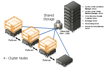
Figure 3: Hyper-V cluster Nodes with Virtual Machine
The sections below covers the detailed configuration for the GPC-POC Infrastructure Environment.
Base OS Server Name | Assigned Machine | Bits | RAM | CPU | Disks | Virtual Switch "Public" | Virtual Switch "Hyper-V & Exchange Replication" | Purpose |
HPB1 (HPV1) | HP Blade 1 | x64 | 64 GB | Quad Core | 2 X 150 GB (300 GB) | Gigabit Ethernet External NIC1 10.1.1.x VLAN1 Corp or VPN | Gigabit Ethernet External NIC2 10.1.2.x VLAN2 Lab internal | Hyper-V (cluster) DDC (SQL, DIT-SC, SCCM, SCOM, SCVMM + Library) Exchange CAS + Hub |
HPB2 (HPV2) | HP Blade 2 | x64 | 64 GB | Quad Core | 2 X 150 GB (300 GB) | Gigabit Ethernet External NIC1 10.1.1.x VLAN1 Corp or VPN | Gigabit Ethernet External NIC2 10.1.2.x VLAN2 Lab internal | Hyper-V failover for HPV1 |
HPB3 (HPV3) | HP Blade 3 | x64 | 32 GB | Quad Core | 2 X 150 GB (300 GB) | Gigabit Ethernet External NIC1 10.1.1.x VLAN1 Corp or VPN | Gigabit Ethernet External NIC2 10.1.2.x VLAN2 Lab internal | Hyper-V (cluster) DAS (273GB - RAID5) Exchange DAG |
HPB4 (HPV4) | HP Blade 4 | x64 | 32 GB | Quad Core | 2 X 150 GB (300 GB) | Gigabit Ethernet External NIC1 10.1.1.x VLAN1 Corp or VPN | Gigabit Ethernet External NIC2 10.1.2.x VLAN2 Lab internal | Hyper-V (cluster) DAS (273GB - RAID5) Exchange DAG |
IBMH1 | IBM 3850 + 2 Fusion IO cards | x64 | 16 GB | Quad Core Intel Xeon Series 7400 | 2 X 650 GB Fusion IO | Gigabit Ethernet External NIC1 10.1.1.x VLAN1 Corp or VPN | N/A | Hyper-V Dual NIC gateway host for remote access AD+DNS until Lenovo server is made available |
IBMH2 | IBM 3850 | x64 | 12 GB | Quad Core Intel Xeon Series 7400 |
| Gigabit Ethernet External NIC1 10.1.1.x VLAN1 Corp or VPN | N/A | iSCSI |
LENH1 | Lenovo RD210 | x64 | 8 GB |
|
| Gigabit Ethernet External NIC1 10.1.1.x VLAN1 Corp or VPN | N/A | Server missing hard drive and won't be available before week of June 21. AD+DNS |
Table 2: Server Physical Machine Table
For more details on the lab configuration, please refer the Excel sheet attached in the Appendix N
- SCVMM Web Portal
This section will show you how to use the SCVMM Web Portal, please find the screen shots in the sequence, which is self-explanatory.
Login to the SCVMM Web Portal as per the screen below. Enter the Admin User id and paword.

Figure 1: Access SCVMM Web Portal
Click on Register New Business Unit
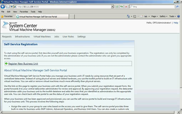
Figure 2: SCVMM Web Portal – Self Service Registration
Please enter all the required field as shown below in the screen.

Figure 3: SCVMM Web Portal – Self Service Registration
Click on "Submit" button

Figure 4: SCVMM Web Portal – Self Service Registration
As you can see the request has been submitted for the approval.
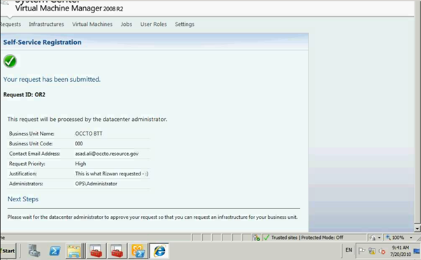
Figure 5: SCVMM Web Portal – Self Service Request Submission
Administrator can see the submission of the request to Approve or Reject.
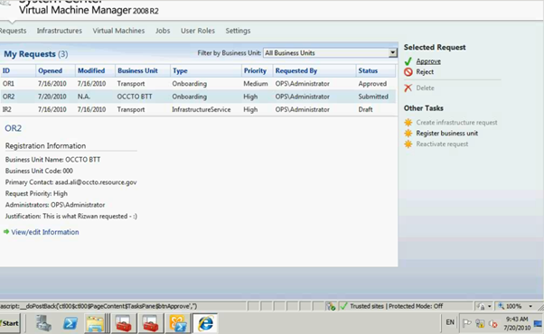
Figure 6: SCVMM Web Portal – Self Service Request Submission
Please enter the Approval / Reject comments.
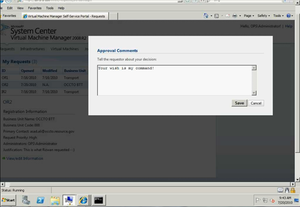
Figure 7: SCVMM Web Portal – Self Service Request Submission
Click on "Create infrastrure request"

Figure 8: SCVMM Web Portal – Self Service Request Approval
Enter the required fields as shown below
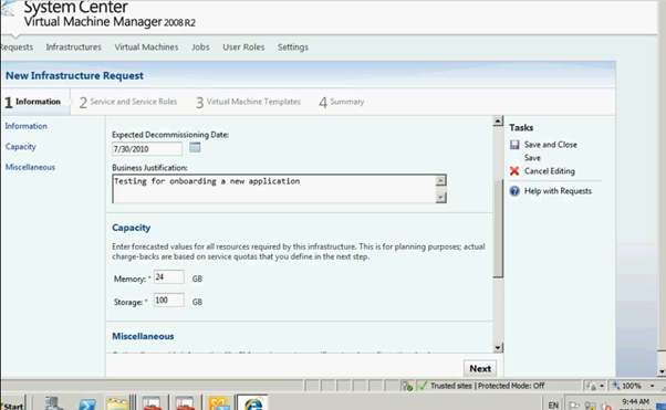
Figure 9: SCVMM Web Portal – Infrasturcture Request
Once completed click on Next button and it will go to Service Setup page

Figure 10: SCVMM Web Portal – Infrasturcture Request
Enter all the info as per the screen below.

Figure 11: SCVMM Web Portal –Service Setup page
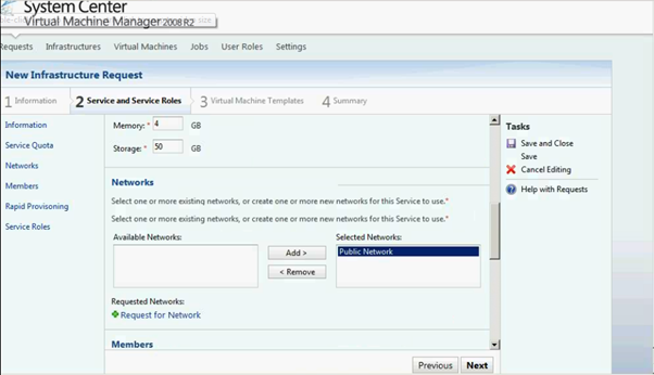
Figure 12: SCVMM Web Portal –Service Setup page
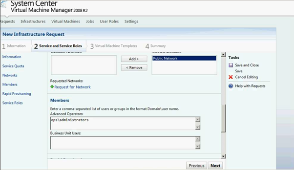
Figure 13: SCVMM Web Portal –Service Setup page
Click on Add Service Role link
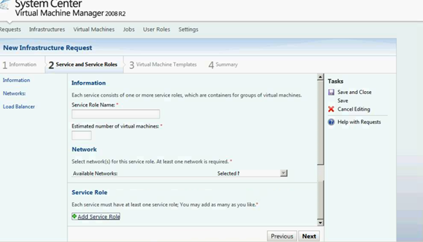
Figure 14: SCVMM Web Portal –Service Setup page
Enter the Service Role info on the below screen

Figure 15: SCVMM Web Portal –Service Role Setup page
Click on next and it will return to Service setup page.
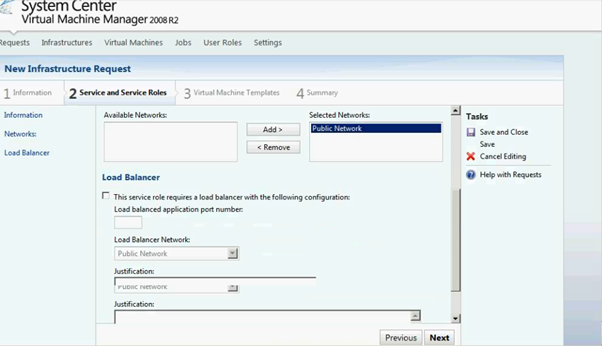
Figure 16: SCVMM Web Portal –Service Role Setup page
As you can see the screen below Service role has been added. You can delete / edit as it's required.

Figure 17: SCVMM Web Portal –Service Setup page

Figure 18: SCVMM Web Portal –Service Setup page
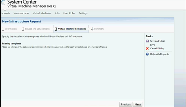
Figure 19: SCVMM Web Portal –Service Setup page
Add the VM Template.
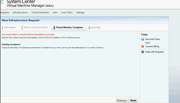
Figure 20: SCVMM Web Portal –Service Setup page
- Configure Exchange Server 2010
The Exchange 2010 OWA is exposing a new administrative interface. In the process OWA went through a name change and what we used to call "Options" became the Exchange Control Panel (ECP). Here is how OWA is venturing into the realm of user administration.
OWA does not stand for Outlook Web Access any longer! Starting from Exchange 2010 this acronym stands for Outlook Web App.
Who cares what the OWA acronym stands for? Certainly not me! What is more interesting is the new functionality this interface provides. Indeed OWA is now venturing in the realm of user administration, broadening its scope, and maybe justifying the name change.
- Exchange Control Panel
As you can imagine OWA continues to be a five star email web client. What is completely new is the addition of the Exchange Control Panel (ECP). When discussing a user interface nothing beats screenshots. So let's logon to OWA using an Exchange Administrator account.
To login, we use the Exchange Control Panel URL:
https://<CAS Server>/ecp
This is the control panel the administrator gets:
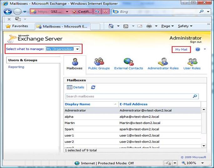
Figure 21: Exchange Server Configuration page
The ECP functionality will change depending on the rights granted to the login user. This administrator is a member of the Exchange Organization Management Universal Security Group, one of the security groups created on installing Exchange 2010. If we login using a regular user account (User4) that was granted no additional rights we of course get less functionality:
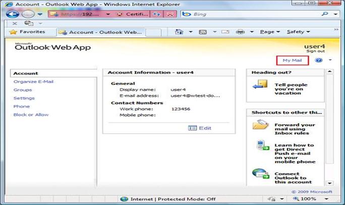
Figure 22: Exchange Server Configuration page
The ECP interface for User4 is very similar to what we already had in the Exchange 2007 OWA Options section. The interface looks different, but here we still find all the options to configure things like Client side rules, Out-of-Office auto-replies, Anti-Spam settings etc.
While looking at User4's interface, take note of the central pane titled 'Account Information - user4'. Clicking on Edit the user is able to modify his account information and personal details.
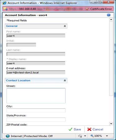
Figure 23: Exchange Server Configuration page
This allows administrators to empower users for them to keep their personal information updated. Indeed one of the key advancements brought about by the ECP, is the ability to better manage users and their configuration.
Looking at User4 we could easily consider the ECP to be little more than a shortcut to the OWA options. Clicking on the 'My Email' link we go to the user mailbox. From here we could click back Options and return to the User4 ECP landing page. However this is only the case because User4 has very limited rights.
Let's go back to the Administrator's ECP landing page shown in the first screenshot. The 'Select what to manage' combo box at the top, is what opens the administrative reach beyond the currently logged on user. Here we have the choice between Myself, My Organization and Another User. Changing the selection to Myself, we get the interface that was presented to User4 when logging to the ECP.
From the combo box we first select 'Another User'. This pops a selection box from where we can identify the user to manage.
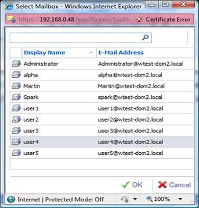
Figure 24: Exchange Server Configuration page
Here I selected User4 and we promptly got hold of his settings. So the administrator is now able to edit User4's options.
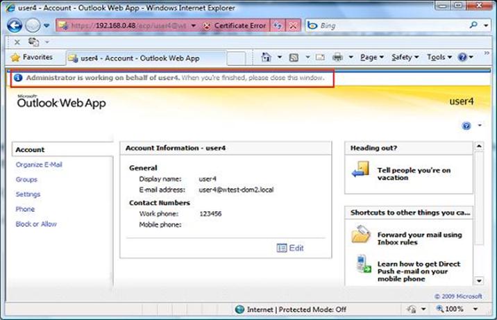
Figure 25: Exchange Server Configuration page
Note how at the top OWA reminds us that we are editing someone else's settings saying: 'Administrator is working on behalf of user4'
What is worth appreciating is that the Administrator account was not granted login rights over User4's mailbox. The Administrator is member of the Exchange Organization Management group that includes the right to manage user settings. This is part of the new Exchange 2010 Role Based Access Control (RBAC) that allows for more granular rights management. We will not discuss RBAC here although we will come across it again shortly.
Once finished with User4 we just close the Browser and go back to the Administrator's ECP landing page. Let's select 'My Organization' at the combo box now.

Figure 26: Exchange Server Configuration page
Here we have two categories Users & Groups and Reporting. At Users & Groups, the first three icons allow us to edit the settings of existing mailboxes, create/edit Distribution Groups and create/edit external Contacts. The ability to create new mailboxes was available in Exchange 2010 Beta but later dropped. Chances are that we will see this back maybe with some service pack. The idea here is to give you a general idea, not that of illustrating each and every setting. So we give a quick look at the Mailbox Details that are configurable here:

Figure 27: Exchange Server Configuration page
Note how this includes amongst others the selection of the Role assignment policy (which is part of RBAC) and the configuration of MailTips.
The remaining two icons at the Users & Groups category give access to more RBAC elements. From Administrator Roles we can configure the membership of Role Groups. Here is how this looks like for the Organization Management Role Group:
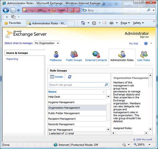
Figure 28: Exchange Server Configuration page
- Configuring Hosted Exchange using PowerShell
PowerShell Script
- Capture all steps with start-transcript in PowerShell
- Snapshot the VMs (Domain Controllers and Exchange Servers)

Figure 29: Start-trascript in PowerShell on exchange server
- Create Service Plans (copy existing service plan files to new names with descriptions)
- C:\Program Files\Microsoft\Exchange Server\V14\ClientAccess\ServicePlans
- Copy the HostingAllFeatures_Sample.servicePlan to Police.servicePlan
<?xml version="1.0" encoding="utf-8" ?>
<!-- ***************************************************************
Warning:
This is a Sample ServicePlan and should not be used as Production Offering.
This file will be replaced in case of Exchange Upgrade.
*************************************************************** -->
<Configuration Version="1.0">
<Organization>
<!-- Global Elements -->
<AddressListsEnabled>true</AddressListsEnabled>
<ApplicationImpersonationEnabled>true</ApplicationImpersonationEnabled>
<AutoForwardEnabled>true</AutoForwardEnabled>
<AutoReplyEnabled>true</AutoReplyEnabled>
<CommonConfiguration>true</CommonConfiguration>
<HideAdminAccessWarningEnabled>true</HideAdminAccessWarningEnabled>
<MailTipsEnabled>true</MailTipsEnabled>
<OfflineAddressBookEnabled>true</OfflineAddressBookEnabled>
<PermissionManagementEnabled>true</PermissionManagementEnabled>
<SearchMessageEnabled>true</SearchMessageEnabled>
<SkipToUAndParentalControlCheckEnabled>true</SkipToUAndParentalControlCheckEnabled>
<SMTPAddressCheckWithAcceptedDomainEnabled>true</SMTPAddressCheckWithAcceptedDomainEnabled>
<!-- Permission Elements -->
<ActiveSyncDeviceDataAccessPermissions>true</ActiveSyncDeviceDataAccessPermissions>
<ActiveSyncPermissions>true</ActiveSyncPermissions>
<ArchivePermissions>true</ArchivePermissions>
<CalendarConnectionPermissions>true</CalendarConnectionPermissions>
<ChangeMailboxPlanAssignmentPermissions>true</ChangeMailboxPlanAssignmentPermissions>
<EwsPermissions>true</EwsPermissions>
<ImapPermissions>true</ImapPermissions>
<JournalingRulesPermissions>true</JournalingRulesPermissions>
<LitigationHoldPermissions>true</LitigationHoldPermissions>
<MailTipsPermissions>true</MailTipsPermissions>
<ManagedFoldersPermissions>true</ManagedFoldersPermissions>
<MessageTrackingPermissions>true</MessageTrackingPermissions>
<ModeratedRecipientsPermissions>true</ModeratedRecipientsPermissions>
<NewUserPasswordManagementPermissions>true</NewUserPasswordManagementPermissions>
<OrganizationalAffinityPermissions>true</OrganizationalAffinityPermissions>
<OutlookAnywherePermissions>true</OutlookAnywherePermissions>
<OWAMailboxPolicyPermissions>true</OWAMailboxPolicyPermissions>
<OWAPermissions>true</OWAPermissions>
<PopPermissions>true</PopPermissions>
<ProfileUpdatePermissions>true</ProfileUpdatePermissions>
<RBACManagementPermissions>true</RBACManagementPermissions>
<RecipientManagementPermissions>true</RecipientManagementPermissions>
<ResetUserPasswordManagementPermissions>true</ResetUserPasswordManagementPermissions>
<RetentionTagsPermissions>true</RetentionTagsPermissions>
<RoleAssignmentPolicyPermissions>true</RoleAssignmentPolicyPermissions>
<SearchMessagePermissions>true</SearchMessagePermissions>
<SetHiddenFromAddressListPermissions>true</SetHiddenFromAddressListPermissions>
<SMSPermissions>true</SMSPermissions>
<TransportRulesPermissions>true</TransportRulesPermissions>
<UserMailboxAccessPermissions>true</UserMailboxAccessPermissions>
<!-- Quota Elements (Always Required) -->
<ContactCountQuota>600000</ContactCountQuota>
<DistributionListCountQuota>300000</DistributionListCountQuota>
<MailboxCountQuota>600000</MailboxCountQuota>
<MailUserCountQuota>300000</MailUserCountQuota>
<RecipientMailSubmissionRateQuota>Unlimited</RecipientMailSubmissionRateQuota>
</Organization>
<MailboxPlans>
<MailboxPlan Name="DefaultMailboxPlan" MailboxPlanIndex="0" ProvisionAsDefault="true">
<!-- Boolean Elements -->
<ActiveSyncEnabled>true</ActiveSyncEnabled>
<EwsEnabled>true</EwsEnabled>
<ImapEnabled>true</ImapEnabled>
<OrganizationalQueryBaseDNEnabled>true</OrganizationalQueryBaseDNEnabled>
<OutlookAnywhereEnabled>true</OutlookAnywhereEnabled>
<PopEnabled>true</PopEnabled>
<ShowInAddressListsEnabled>true</ShowInAddressListsEnabled>
<SkipResetPasswordOnFirstLogonEnabled>true</SkipResetPasswordOnFirstLogonEnabled>
<!-- Permission Elements-->
<ActiveSyncDeviceDataAccessPermissions>true</ActiveSyncDeviceDataAccessPermissions>
<ActiveSyncPermissions>true</ActiveSyncPermissions>
<AutoGroupPermissions>true</AutoGroupPermissions>
<ImapPermissions>true</ImapPermissions>
<MailTipsPermissions>true</MailTipsPermissions>
<MessageTrackingPermissions>true</MessageTrackingPermissions>
<ModeratedRecipientsPermissions>true</ModeratedRecipientsPermissions>
<OrganizationalAffinityPermissions>true</OrganizationalAffinityPermissions>
<PopPermissions>true</PopPermissions>
<ProfileUpdatePermissions>true</ProfileUpdatePermissions>
<ResetUserPasswordManagementPermissions>true</ResetUserPasswordManagementPermissions>
<RetentionTagsPermissions>true</RetentionTagsPermissions>
<SMSPermissions>true</SMSPermissions>
<UserMailboxAccessPermissions>true</UserMailboxAccessPermissions>
<!-- Quotas Elements -->
<MaxReceiveTransportQuota>1GB</MaxReceiveTransportQuota>
<MaxRecipientsTransportQuota>5000</MaxRecipientsTransportQuota>
<MaxSendTransportQuota>1GB</MaxSendTransportQuota>
<ProhibitSendReceiveMaiboxQuota>10GB</ProhibitSendReceiveMaiboxQuota>
</MailboxPlan>
</MailboxPlans>
</Configuration>
- Copy the HostingBusinessMAPI_Sample.servicePlan to Tourism.servicePlan
<?xml version="1.0" encoding="utf-8" ?>
<!-- ***************************************************************
Warning:
This is a Sample ServicePlan and should not be used as Production Offering.
This file will be replaced in case of Exchange Upgrade.
*************************************************************** -->
<Configuration Version="1.0">
<Organization>
<!-- Global Elements -->
<AddressListsEnabled>true</AddressListsEnabled>
<ApplicationImpersonationEnabled>true</ApplicationImpersonationEnabled>
<AutoForwardEnabled>true</AutoForwardEnabled>
<AutoReplyEnabled>true</AutoReplyEnabled>
<CommonConfiguration>true</CommonConfiguration>
<HideAdminAccessWarningEnabled>true</HideAdminAccessWarningEnabled>
<MailTipsEnabled>true</MailTipsEnabled>
<OfflineAddressBookEnabled>true</OfflineAddressBookEnabled>
<PermissionManagementEnabled>true</PermissionManagementEnabled>
<SearchMessageEnabled>true</SearchMessageEnabled>
<SkipToUAndParentalControlCheckEnabled>true</SkipToUAndParentalControlCheckEnabled>
<SMTPAddressCheckWithAcceptedDomainEnabled>true</SMTPAddressCheckWithAcceptedDomainEnabled>
<!-- Permission Elements -->
<ActiveSyncDeviceDataAccessPermissions>true</ActiveSyncDeviceDataAccessPermissions>
<ActiveSyncPermissions>true</ActiveSyncPermissions>
<ArchivePermissions>true</ArchivePermissions>
<CalendarConnectionPermissions>true</CalendarConnectionPermissions>
<ChangeMailboxPlanAssignmentPermissions>true</ChangeMailboxPlanAssignmentPermissions>
<EwsPermissions>true</EwsPermissions>
<ImapPermissions>true</ImapPermissions>
<JournalingRulesPermissions>true</JournalingRulesPermissions>
<LitigationHoldPermissions>true</LitigationHoldPermissions>
<MailTipsPermissions>true</MailTipsPermissions>
<MessageTrackingPermissions>true</MessageTrackingPermissions>
<ModeratedRecipientsPermissions>true</ModeratedRecipientsPermissions>
<NewUserPasswordManagementPermissions>true</NewUserPasswordManagementPermissions>
<OrganizationalAffinityPermissions>true</OrganizationalAffinityPermissions>
<OutlookAnywherePermissions>true</OutlookAnywherePermissions>
<OWAMailboxPolicyPermissions>true</OWAMailboxPolicyPermissions>
<OWAPermissions>true</OWAPermissions>
<PopPermissions>true</PopPermissions>
<ProfileUpdatePermissions>true</ProfileUpdatePermissions>
<RBACManagementPermissions>true</RBACManagementPermissions>
<RecipientManagementPermissions>true</RecipientManagementPermissions>
<ResetUserPasswordManagementPermissions>true</ResetUserPasswordManagementPermissions>
<RetentionTagsPermissions>true</RetentionTagsPermissions>
<RoleAssignmentPolicyPermissions>true</RoleAssignmentPolicyPermissions>
<SearchMessagePermissions>true</SearchMessagePermissions>
<SetHiddenFromAddressListPermissions>true</SetHiddenFromAddressListPermissions>
<SMSPermissions>true</SMSPermissions>
<TransportRulesPermissions>true</TransportRulesPermissions>
<UserMailboxAccessPermissions>true</UserMailboxAccessPermissions>
<!-- Quota Elements (Always Required) -->
<ContactCountQuota>600000</ContactCountQuota>
<DistributionListCountQuota>300000</DistributionListCountQuota>
<MailboxCountQuota>600000</MailboxCountQuota>
<MailUserCountQuota>600000</MailUserCountQuota>
<RecipientMailSubmissionRateQuota>500</RecipientMailSubmissionRateQuota>
</Organization>
<MailboxPlans>
<MailboxPlan Name="DefaultMailboxPlan" MailboxPlanIndex="0" ProvisionAsDefault="true">
<!-- Boolean Elements -->
<ActiveSyncEnabled>true</ActiveSyncEnabled>
<EwsEnabled>true</EwsEnabled>
<ImapEnabled>true</ImapEnabled>
<OrganizationalQueryBaseDNEnabled>true</OrganizationalQueryBaseDNEnabled>
<OutlookAnywhereEnabled>true</OutlookAnywhereEnabled>
<PopEnabled>true</PopEnabled>
<ShowInAddressListsEnabled>true</ShowInAddressListsEnabled>
<SkipResetPasswordOnFirstLogonEnabled>true</SkipResetPasswordOnFirstLogonEnabled>
<!-- Permission Elements-->
<ActiveSyncDeviceDataAccessPermissions>true</ActiveSyncDeviceDataAccessPermissions>
<ActiveSyncPermissions>true</ActiveSyncPermissions>
<AutoGroupPermissions>true</AutoGroupPermissions>
<ImapPermissions>true</ImapPermissions>
<MailTipsPermissions>true</MailTipsPermissions>
<MessageTrackingPermissions>true</MessageTrackingPermissions>
<ModeratedRecipientsPermissions>true</ModeratedRecipientsPermissions>
<OrganizationalAffinityPermissions>true</OrganizationalAffinityPermissions>
<PopPermissions>true</PopPermissions>
<ProfileUpdatePermissions>true</ProfileUpdatePermissions>
<ResetUserPasswordManagementPermissions>true</ResetUserPasswordManagementPermissions>
<RetentionTagsPermissions>true</RetentionTagsPermissions>
<SMSPermissions>true</SMSPermissions>
<UserMailboxAccessPermissions>true</UserMailboxAccessPermissions>
<!-- Quotas Elements -->
<MaxReceiveTransportQuota>20MB</MaxReceiveTransportQuota>
<MaxRecipientsTransportQuota>5000</MaxRecipientsTransportQuota>
<MaxSendTransportQuota>20MB</MaxSendTransportQuota>
<ProhibitSendReceiveMaiboxQuota>25GB</ProhibitSendReceiveMaiboxQuota>
</MailboxPlan>
</MailboxPlans>
</Configuration>
- Edit the mailbox plans (if req'd) for each service plan
- Edit the serviceplan files created above, MailboxPlan section is near the bo
- Add service plans to the service plan map
- Edit the ServicePlanHostingRemap.csv and add entries for Police and Tourism
- Tourism,5,Tourism
- Police,6,Police
# ServicePlanHostingRemap.csv, version 1
#Column headers:
#ProgramId,OfferId,ServicePlanName
# Hosting Sample Offers
##################
HostingSample,2,HostingAllFeatures_Sample
HostingSample,3,HostingBusinessMapi_Sample
HostingSample,4,HostingBusinessNonMapi_Sample
OCCTO,5,OCCTO_ServicePlan
Transportation,6,Transportation_ServicePlan
- Create Tenant Organizations
New-Organization -Name "police.ontoso.gov" -DomainName "police.contoso.gov" -Location "en-us" -ProgramId "Tourism" -OfferId "5"
New-Organization -Name "police.ontoso.gov" -DomainName "police.contoso.gov" -Location "en-us" -ProgramId "Police" -OfferId "6"
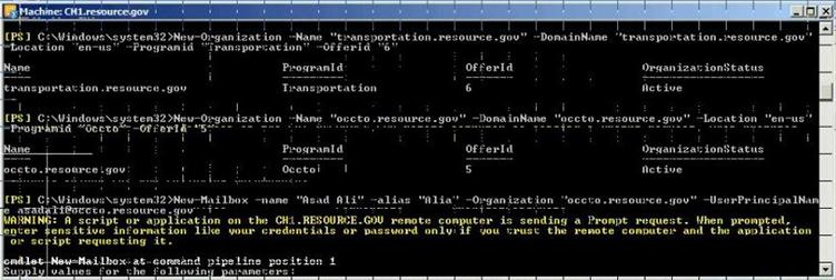
Figure 30: Create Tenenant Organization using PowerShell
- Create users
New-Mailbox -name "Pamela Erling" -alias "pamela" -Organization "police.contoso.gov" -UserPrincipalName pamela@police.contoso.gov
New-Mailbox -name "Patty Fisher" -alias "patty" -Organization "police.contoso.gov" -UserPrincipalName patty@police.contoso.gov
New-Mailbox -name "Tom Gregory" -alias "tom" -Organization "tourism.contoso.gov" -UserPrincipalName tom@tourism.contoso.gov
New-Mailbox -name "Ted Johnson" -alias "ted" -Organization "tourism.contoso.gov" -UserPrincipalName ted@tourism.contoso.gov
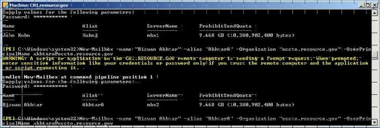
Figure 31: Create New User mailbox using PowerShell
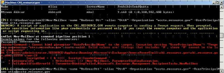
Figure 32: Create New User mailbox using PowerShell
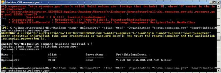
Figure 33: Create New User mailbox using PowerShell
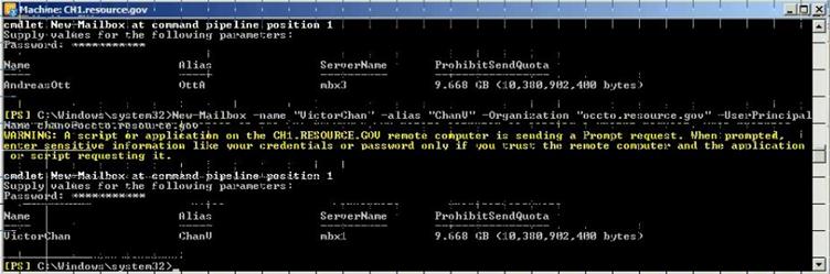
Figure 34: Create New User mailbox using PowerShell
- Check differences with Get-Mailbox
PowerShell Script
get-mailbox -organization police.contoso.gov
get-mailbox -organization tourism.contoso.gov
- Logon to OWA
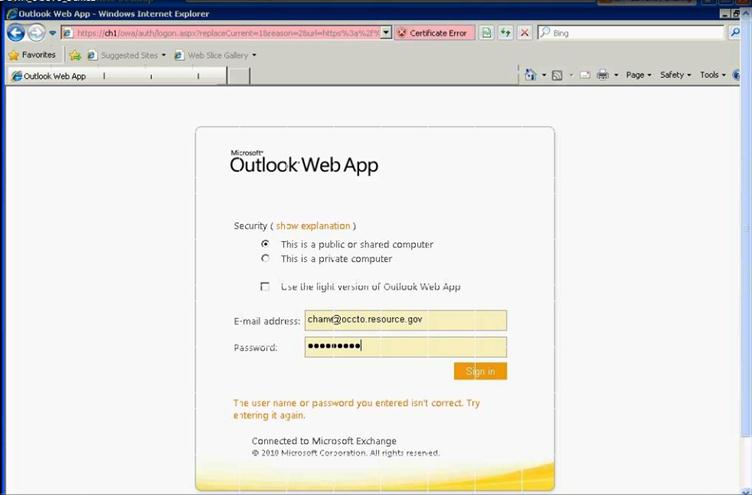
Figure 35: Access OWA to verify user mailbox setup
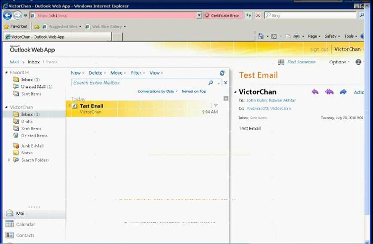
Figure 36: Access OWA to verify user mailbox setup
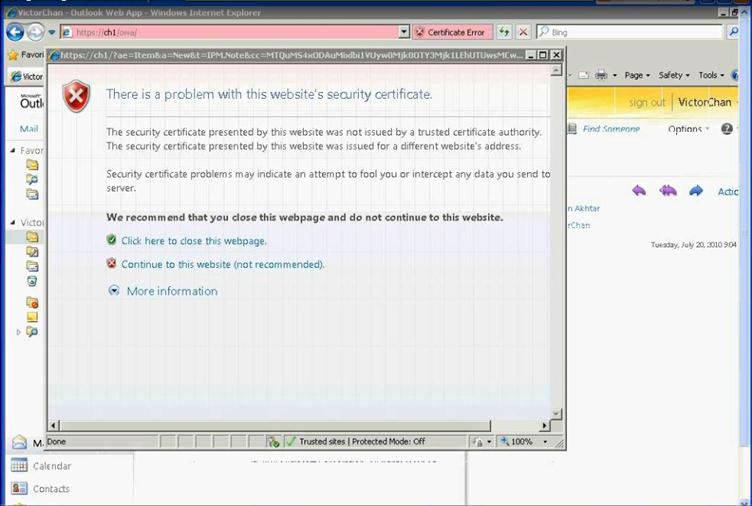
Figure 37: Access OWA to verify user mailbox setup
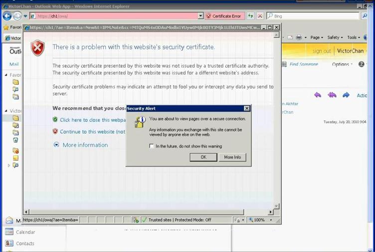
Figure 38: Access OWA to verify user mailbox setup
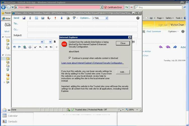
Figure 39: Access OWA to verify user mailbox setup
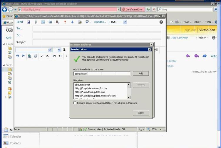
Figure 40: Access OWA to verify user mailbox setup
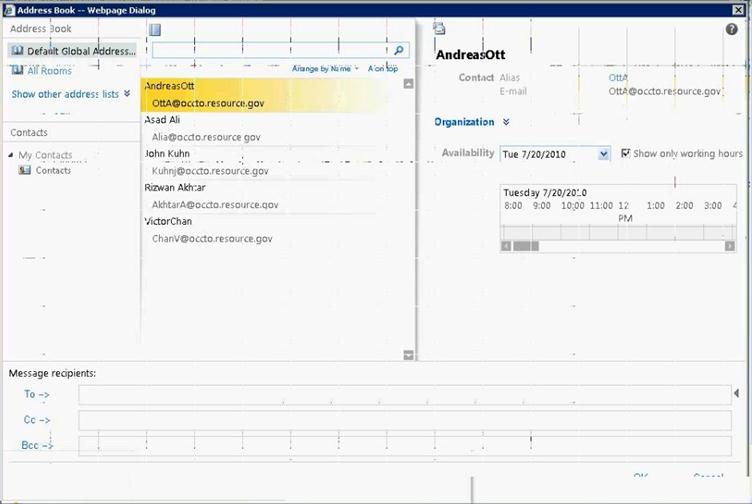
Figure 41: Access OWA to verify user mailbox setup

Figure 42: Access OWA to verify user mailbox setup

Figure 43: Access OWA to verify user mailbox setup
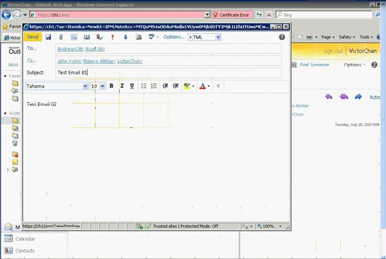
Figure 44: Access OWA to verify user mailbox setup
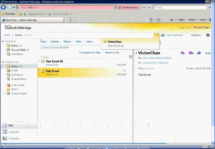
Figure 45: Access OWA to verify user mailbox setup

Figure 46: Access OWA to verify user mailbox setup
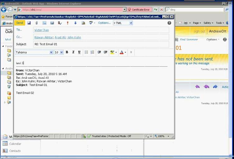
Figure 47: Access OWA to verify user mailbox setup
- TroubleShooting refrences
- Troubleshooting VMM
Please follow the link for troubleshooting any issue with VMM http://technet.microsoft.com/en-us/library/cc764272.aspx
- Troubleshooting Exchange Setup
- Troubleshooting the Exchange Management Console
http://technet.microsoft.com/en-us/library/dd876948.aspx
- Troubleshooting the Exchange Management Shell
http://technet.microsoft.com/en-us/library/dd351136.aspx
Appendix A – Hyper-V Host Server Farm Pattern
The Host Server Farm architecture pattern is illustrated below.
The architecture consists of a multi-node Windows Server 2008 R2 cluster leveraging a shared storage system such as an iSCSI or Fibre Channel storage area network (SAN) and storage array. Each node of the cluster runs Windows Server 2008 R2 with Hyper-V.
- This pattern provides server consolidation and high availability on a greater scale.
- Supports up to 16 nodes in a single cluster configuration.
- Virtual machines can run on any node of the cluster.
- In the event of a node failure, the virtual machines will be restarted automatically on any node that has the available capacity to host the failed resources.
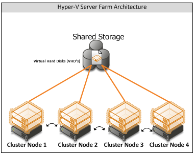
Figure i: Hyper-V Server Farm pattern
Information
The Host Server Farm pattern provides high availability as well as better use of hardware since a single physical host can serve a passive node for up to 15 active nodes.
Appendix B – Host Cluster patterns
- No Majority – Disk Only
The cluster has quorum if one node is available and in communication with a specific disk in the cluster storage. Only the nodes that are also in communication with that disk can join the cluster.
Microsoft Recommendations
This pattern is not recommended for High Availability as the disk can be a single point of failure.
- Node Majority
Node Majority is a quorum model where each node that is available and in communication can vote. The cluster functions only with a majority of the votes, that is, more than half.
Microsoft Recommendations
This pattern is recommended in Failover Cluster deployments containing an odd number of nodes.
- Node and Disk Majority
Node and Disk Majority is a quorum model in Windows Server 2008 R2 Failover Clustering. In this quorum model, a cluster remains active until half of the nodes and its witness disk is available. In case, the witness disk is offline, a cluster requires a majority of nodes to be up and running in order to successfully run the cluster. This model contains two or more nodes connected to a shared storage device. The witness disk is stored on the cluster disk. This quorum model is used in scenarios where all nodes are connected to a shared storage device on the same network.
Microsoft Recommendations
This pattern is recommended in Failover Cluster deployments containing an even number of nodes.
- Node and File Share Majority
The file share witness feature is an improvement to the current Majority Node Set (MNS) quorum model. This feature lets you use a file share that is external to the cluster as an additional "vote" to determine the status of the cluster.
Microsoft Recommendations
This pattern is recommended in Failover Cluster deployments containing an even number of nodes and for Multi-Site failover clusters.
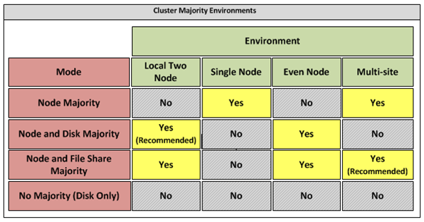
Figure ii: Host Cluster Patterns
Appendix C – Network Architecture
The network architecture of the host server is a frequently overlooked topic in host server sizing because Gigabit Ethernet NICs are now very inexpensive and most servers have at least two built in. The topic is important, however, because it is directly impacted by the host server architecture pattern selected. If one of the two host server cluster patterns is selected, a dedicated NIC per server is required for the cluster private (heartbeat) network. Gigabit Ethernet is a high-speed network transport, though a host server with a large number of guests may require greater than Gigabit speed, thus requiring additional NICs. Finally, it is recommended that each host server have a NIC dedicated to the host itself for network I/O and management.
A fairly large number of NICs per host server may be required. Recently, 10-Gigabit Ethernet has become commonly available and is starting to drift lower in price, similar to the way Gigabit Ethernet has done over the years. The ability for servers to utilize 10-Gigabit Ethernet NICs is a significant factor in increasing the consolidation ratio.
Microsoft Recommendations
Use multiple NICs and multi-port NICs on each host server.
- One NIC dedicated to the host machine only for management purposes
- One NIC dedicated to the private Cluster Heartbeat network
- One NIC dedicated to the Live Migration network
- One or more NICs dedicated to the guest virtual machines (use 10 gpbs NICS for highest consolidation)
- Two or more NICs dedicated to iSCSI with MPIO
Dedicate at least one NIC/Port on each host server for guest virtual machine network I/O. For maximum consolidation ratio, utilize one or more 10-Gigabit Ethernet NICs to virtual machine network I/O.
Warning
Microsoft does not support the use of NIC teaming software. Support for these third-party technologies must be provided by the vendor.
Appendix D - Processor Architecture
Windows Server 2008 R2 with Hyper-V requires x64 processor architecture from Intel or AMD, as well as support for hardware execute disable and hardware virtualization such as Intel VT or AMD-V.
Both Intel and AMD provide a wide range of processors that are appropriate for host servers. The industry competition between the two is very tight and at any one time; one may have a performance advantage over the other. Regardless of which manufacturer is chosen, several performance characteristics are important.
The number of processor cores is a key performance characteristic. Windows Server 2008 R2 with Hyper-V makes excellent use of multi-core processors, so the more cores the better. Another important characteristic is the processor clock speed, which is the speed at which all cores in the processor will operate. It's important because it will be the clock speed of all of the guest virtual machines. This is a key variable in the consolidation ratio because it impacts the amount of candidates that the host server can handle and the speed at which those guests will operate. As an example, choosing 2 GHz processor rather than a 3 GHz processor on a server that will host 20 guests means that all of those guests will run only at 2 GHz.
At a lower level of detail, the server processor architectures make design choices in terms of the type and quantity of processor cache, memory controller architecture, and bus/transport architecture. A detailed analysis of these factors is beyond the scope of this document.
Microsoft Recommendations
x64 processor architectures are required for all Hyper-V host server architecture patterns. If you are purchasing new servers, we recommend working with your server vendor to ensure that the selected hardware is capable of running Windows Server 2008 R2 and Hyper-V, and that it is validated for Windows Server 2008 R2 failover clustering. For new servers, we recommend selecting the maximum number of cores per processor available and choosing the fastest or second fastest clock speed available.
Appendix E – Memory Architecture
Once the system architecture and processor architecture choices are made, there are relatively few options remaining for memory architecture because it is usually predetermined by the manufacturer/system/processor combination. The memory architecture choices that remain are typically quantity, speed, and latency. For Hyper-V, the most important memory architecture choice is the quantity of RAM. Most consolidated workloads (that is, individual guest virtual machines) will require at least 512 MB to 1 GB of RAM or more. Since most commodity four-socket servers can only cost effectively support between 32 and 128 GB of RAM, this is frequently the limiting factor in host server capacity.
The quantity of RAM is a more important factor than RAM speed or latency. Once the maximum amount of RAM that is cost effective is determined, if there is a remaining choice between speed and latency, choosing the memory with lower latency is recommended.
Microsoft Recommendations
Given the system and processor architectures already selected, we recommend utilizing the maximum amount of RAM that can be cost effectively added to the host system. Typically, there is a price point where the cost of moving to the next DIMM size (that is, 2 GB DIMMs to 4 GB DIMMs) is more than twice the cost, and in some cases, it approaches the cost of an entire server. We recommend fully populating the server up to that price point. For example, if the server has 8 DIMM slots and 4 GB DIMMs are much more than twice the cost of 2 GB DIMMs, we recommend fully populating the server with 2 GB DIMMs and considering a second host server if additional capacity is required.
For all host server architecture patterns, we recommend a minimum of 16 GB of RAM.
For Multi-Node Host Server Farm patterns, we recommend a minimum of 64 GB per server.
Appendix F - Drive types
The type of hard drive utilized in the host server or the storage array the host servers will have a significant impact on the overall storage architecture performance. The critical performance factors for hard disks are the interface architecture (for example, U320 SCSI, SAS, SATA), the rotational speed of the drive (7200, 10k, 15k RPM), and the average latency in milliseconds. Additional factors, such as the cache on the drive, and support for advanced features, such as Native Command Queuing (NCQ), can improve performance. As with the storage connectivity, high IOPS and low latency are more critical than maximum sustained throughput when it comes to host server sizing and guest performance. When selecting drives, this translates into selecting those with the highest rotational speed and lowest latency possible. Utilizing 15k RPM drives over 10k RPM drives can result in up to 35% more IOPS per drive.
SCSI
SCSI drives are rapidly being replaced by SATA, SAS, and Fibre Channel drives. SCSI drives are not recommended for new host server architectures; however, existing servers with U320 SCSI drives can provide excellent performance characteristics.
SATA
SATA drives are a low cost and relatively high performance option for storage. SATA drives are available primarily in the 1.5 GB/s and 3.0 GB/s standards (SATA I and SATA II) with a rotational speed of 7200 RPM and average latency of around 4 ms. There are a few SATA I drives that operate at 10k RPM and average latency of 2 ms that can provide an excellent low cost storage solution.
SAS
SAS drives are typically much more expensive than SATA drives but can provide significantly higher performance in both throughput, and more importantly, low latency. SAS drives typically have a rotational speed of 10k or 15k RPM with an average latency of 2 to 3 ms.
Fibre Channel
Fibre Channel drives are usually the most expensive and typically have similar performance characteristics to SAS drives but use a different interface. The choice of Fibre Channel or SAS drives is usually determined by the choice of storage array. As with SAS, they are typically offered in 10k and 15k RPM variants with similar average latencies.
Microsoft Recommendations
Fibre Channel 15k RPM drives are recommended for Host Server Farm patterns.
If you are using a Fibre Channel SAN, ensure that the switch and director infrastructure is sized to handle the large amount of storage I/O that will be generated from the consolidated servers.
Appendix G - Disk Redundancy Architecture
Redundant Array of Inexpensive Disk (RAID) is strongly recommended for all Hyper-V host storage. By definition, Hyper-V hosts run and store data from multiple workloads. RAID is necessary to ensure that availability is maintained during disk failure. In addition, if properly selected and configured, RAID arrays can provide improvements in overall performance.
RAID 1
RAID 1 is disk mirroring. Two drives store identical information so that one is a mirror of the other. For every disk operation, the system must write the same information to both disks. Because dual write operations can degrade system performance, many employ duplexing, where each mirror drive has its own host adapter. While the mirror approach provides good fault tolerance, it is relatively expensive to implement because only half of the available disk space can be used for storage, while the other half is used for mirroring.
RAID 5
Also known as striping with parity, this level is a popular strategy for low- or mid-range storage systems. RAID 5 stripes the data in large blocks across the disks in an array. RAID 5 writes parity data across all the disks in the RAID 5 set. Data redundancy is provided by the parity information. The data and parity information is arranged on the disk array so that the two types of information are always on different disks. Striping with parity can offer better performance than disk mirroring (RAID 1). However, when a stripe member is missing, read performance is decreased (for example, when a disk fails). RAID 5 is a less expensive option because it utilizes drive space more efficiently than RAID 1.
RAID 1+0 (RAID 10)
For more information about these types of RAID systems, contact your storage hardware vendor.
RAID 1 or RAID 1+0 is recommended for the system volume in all host server architecture patterns.
RAID 1+0 is recommended for the data volumes in the Host Server Farm patterns.
Appendix H - Fibre Channel Storage Area Network
Architecture | Throughput (theoretical max Megabyte/sec) |
iSCSI (Gigabit Ethernet) | 125 MB/s |
Fibre Channel (2 GFC) | 212.5 MB/s |
SATA (SATA II) | 300 MB/s |
SCSI (U320) | 320 MB/s |
SAS | 375 MB/s |
Fibre Channel (4 GFC) | 425 MB/s |
Table i: Comparison of Disk Controller throughput speeds
Appendix I - Disk Controller or HBA Interface
Architecture | Throughput (theoretical max Megabyte/sec) |
iSCSI (Gigabit Ethernet) | 125 MB/s |
Fibre Channel (2 GFC) | 212.5 MB/s |
SATA (SATA II) | 300 MB/s |
SCSI (U320) | 320 MB/s |
SAS | 375 MB/s |
Fibre Channel (4 GFC) | 425 MB/s |
Table ii: Comparison of Disk Controller Interfaces
4 GFC Fibre Channel is recommended for the Host Server Farm architecture pattern.
Appendix J - Cluster Shared Volumes
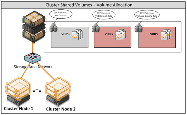
Figure iii: CSV Volume Allocation
Appendix K - System Center Virtual Machine Manager R2 2008
Virtual Machine Manager Server
Delegated Management and Provisioning Web Portal
Appendix L – Hyper-V Overview

Figure iv: Hyper-V Environment
Appendix M – Hardware Architecture
The recommended server configuration for the Hyper-V Management Server is:
Server Architecture |
2 x Xeon Quad Core Processors x64 |
32 GB of RAM |
2 x 150 GB (300GB) RAID 1 OS Partition with Array - SAS RAID Controller |
Local or External Storage (ISCSI/FC) |
Up to 4 x 1GBps Network ports (Management/Virtual/External and potentially ISCSI Networks) |
Table iv: Management Host Server Architecture
The Virtualised Management Servers which will be used have the following resource requirements:
The recommended server specification for each cluster node is:
Server Architecture |
2 x Xeon Quad Core Processors x64 |
48GB of RAM |
2 x 150 GB (300GB) RAID 1 OS Partition with Array - SAS RAID Controller |
Optional 2GBps FC HBA (if using FC SAN) |
External Storage (ISCSI/FC) – 5TB |
Up to 3 x 1GBps Network ports (Management/Virtual/Live Migration/ Heartbeat and potentially ISCSI Networks) Minimum required is 2. |
Table v: Cluster Host Server Architecture
The Hyper-V host servers should utilise local storage for the operating system and the paging file.
The drives utilised by the operating system should be configured as RAID 1.
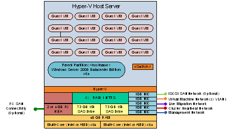 Figure iv: Cluster Host Server Overview
Appendix N – References
- For Deployment Scenario more details please refer to the link http://www.microsoft.com/downloads/details.aspx?FamilyID=fef38539-ae5a-462b-b1c9-9a02238bb8a7&displaylang=en and download a file VMM08R2_VMMSSPDocumentation.zip for more information.
- Failover clustering documents http://technet.microsoft.com/en-us/library/cc732181(WS.10).aspx#BKMK_Install
- Build SCVMM & SQLVM http://technet.microsoft.com/en-us/library/cc764289.aspx
- SQL 2008 Install http://technet.microsoft.com/en-us/library/bb500469(SQL.100).aspx
http://technet.microsoft.com/en-us/library/ms143506(SQL.100).aspx
- Exchange 2010 SP1 download link http://technet.microsoft.com/en-us/evalcenter/dd185495.aspx
- Unified Access Gateway http://technet.microsoft.com/en-us/library/dd857385.aspx
- For Deployment Scenario more details please refer to the link http://www.microsoft.com/downloads/details.aspx?FamilyID=fef38539-ae5a-462b-b1c9-9a02238bb8a7&displaylang=en and download a file VMM08R2_VMMSSPDocumentation.zip for more information.
- Lab Configuration excel sheet


 浙公网安备 33010602011771号