
私有云设计文档
Table of Contents
3 Constraints and Assumptions 2
4.1.1 Active Directory Server (DDC1-DC01) 4
4.1.2 Firewall Server (DDC1-TMG01) 4
4.1.3 Remote Desktop Gateway Server (DDC1-TSG01) 5
4.1.4 Provisioning Server (DDC1-APF01) 5
4.1.5 Web Portal Server (DDC1-WEB01) 5
4.1.6 System Center Virtual Machine Manager Server (DDC1-SCVMM01) 6
4.1.7 System Center Operations Manager Server (DDC1-SCOM01) 7
4.1.8 Hyper-V Server Cluster 7
4.5 Security Considerations 10
4.5.1 End User Access to the solution 10
4.5.3 Host Operating System Configuration 10
5.1.1 Hyper-V Management Server 11
5.1.2 Hyper-V Cluster Nodes 12
5.1.5 Operating System Version 13
5.1.6 Cluster Host Server Overview 13
5.2.1 Virtual Machine Networking 15
6 G-Cloud Demonstrator Web site 17
6.3 Setting the Cost Center and SMTP Settings 20
6.3.3 Set Parameters Scheduled Task 21
7 Deploying G-Cloud Demonstrator 22
8.1 Terms and Abbreviations 24
Appendix A – Hyper-V Host Server Farm Pattern 25
Appendix B – Host Cluster patterns 26
Node and File Share Majority 26
Appendix C – Network Architecture 28
Appendix D - Processor Architecture 29
Appendix E – Memory Architecture 30
Appendix G - Disk Redundancy Architecture 32
Appendix H - Fibre Channel Storage Area Network 33
Appendix I - Disk Controller or HBA Interface 34
Appendix J - Cluster Shared Volumes 35
Appendix K - System Center Virtual Machine Manager R2 2008 37
Virtual Machine Manager Server 37
Microsoft SQL Server Database 37
Delegated Management and Provisioning Web Portal 38
Table of Tables
Table 2: Management Host Server Architecture 11
Table 3: Cluster Host Server Architecture 12
Table 4: Terms and Abbreviations 24
Table 5: Comparison of Disk Controller throughput speeds 33
Table 6: Comparison of Disk Controller Interfaces 34
Table of Figures
Figure 1: G-Cloud Demonstrator Network Overview 8
Figure 2: Cluster Host Server Overview 13
Figure 3: Cluster Node Network Overview 14
Figure 4: Hyper-V Server Farm pattern 25
Figure 5: Host Cluster Patterns 27
Figure 6: CSV Volume Allocation 36
The scope of this document is concerned with Microsoft technologies only.
Assumption | Explanation |
Physical environment | It is assumed that a server environment exists with enough floor space, power, air conditioning, physical security etc. |
Stable network | It is assumed that the local and wide area network infrastructure which includes physical components switches, routers, cable etc. And the logical components like routing, broadcasts, collisions etc. Are stable and under control. Having an unstable network can result in unexpected behaviour. |
The Threat Management Gateway provides the secured end-user access to the Web Portal.
External Web URL: http://<external web ip address as per your environment>/GCloud
Web Chaining Rule – This will need to be updated with the details of your upstream proxy server.
APFSrc – holds the library of applications used by the automated build
APFTree – holds the manifest files and scripts used by the automated build
The Web Portal Server host the end-user interface to the G-Cloud Demonstrator.
Internal Web URL: http://ddc1-web01.ddc1.local/GCloud
Further info around the web site can be found in Section 6
- System Center Virtual Machine Manager Server (DDC1-SCVMM01)
The System Center Virtual Machine Manager is installed into the management network as a virtual machine; this instance manages the Hyper-V host servers and virtual machines. In addition, the administrator console and failover clustering toolset are installed for management of the server infrastructure. The Self-Service Portal is also implemented with role specific administration, as this functionality is used for accessing the provisioned virtual machines.
The Library holds a number of sysprepped images and hardware templates:
Name | Type | Notes |
| | |
| | |
| | |
| | |
| | |
| | |
| | |
| | |
| | |
| | |
| | |
| | |
| | |
| | |
- System Center Operations Manager Server (DDC1-SCOM01)
The System Center Operations Manager is installed for providing a means of consolidated health monitoring across both the management servers and the provisioned virtual machines.
Additional Management Packs installed:
- SUSE and Red Hat Linux
Note: That although the Linux management packs are installed, the Linux Images provided as part of the Solution do not contain the SCOM Agent and so will not be automatically monitored. This feature may be provided at a later date.
- Hyper-V Server Cluster
The virtualisation platform onto which new virtual machines are provisioned consists of a multi-node Windows Server 2008 R2 cluster leveraging a shared storage area network (SAN) array with a Node and Disk Majority cluster. Each node of the cluster runs Windows Server 2008 R2 Enterprise Edition Hyper-V. Each active node in the cluster hosts and runs the virtual machines.
In the event of a failure of one of the nodes or planned maintenance, cluster failover occurs. The virtual machine guest(s) are failed over to the remaining nodes in the site boundary. If resiliency against the failure of active nodes is desired, then the surviving nodes must be able to take on the entire load of the failing nodes. The recommended approach is to have each node be physically identical and size the load on each node so that it achieves the above rules.
- Network
The Network design has to accommodate the virtualised networking requirements for both the management server infrastructure and the provisioned virtual machines. Therefore, to simplify the portability of the solution we have chosen to implement a private IP addressing scheme for the management servers. This means that access to them is only via the host server unless specific routes are added.
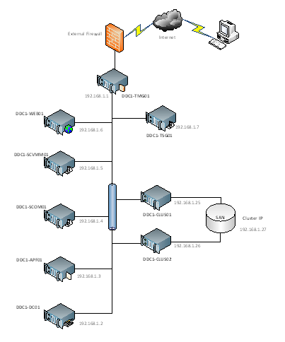
Figure 1: G-Cloud Demonstrator Network Overview
In addition, the physical management server(s) and the host cluster must both be on the same VLAN such that the virtual SCVMM and AD Servers can manage the host cluster and new virtual machines can be provisioned to it.
- Storage
The Storage design can be kept as simple as possible – either a FC/ISCSI connection is needed to the SAN and enough disk space to cater for the potential number of virtual machines is required for the host cluster.
- Backup and Restore
As this is purely a demonstrator, Virtual machines will not be backed up.
- Security Considerations
- End User Access to the solution
Access to the solution for end-users is via a HTTP link over the Internet and through the TMG Server to the Web Portal. It is assumed that the hosting environment has an outer firewall limiting traffic reaching the DDC1-TMG01 Server.
Note: As this is a pure demonstrator solution, the security of the environment will need to be reviewed against the requirements of the environment into which it is being deployed and as such firewall rules and further security lockdown measures may be required.
- Hyper-V
Microsoft Hyper-V was designed to minimize the attack surface on the virtual environment. The Hypervisor itself is isolated to a microkernel, independent of third-party drivers. Host portions of the Hyper-V activities are isolated in a parent partition, separate from each guest. The parent partition itself is a virtual machine. Each guest virtual machine operates in its own child partition.
These are the recommended security best practices on a Hyper-V environment, cumulative to the usual security best practices for physical servers:
- Securing the communications between the Hyper-V server and its administrators and users.
- Host Operating System Configuration
- Keep the management operating system up to date with the latest security updates.
- Use a separate network with a dedicated network adapter for the management operating system of the physical Hyper-V computer.
- Secure the storage devices where you keep virtual machine resource files.
- Harden the management operating system using the baseline security setting recommendations described in the Windows Server 2008 R2 Security Compliance Management Toolkit.
- Configure any real-time scanning antivirus software components installed on the management operating system to exclude Hyper-V resources.
- Do not use the management operating system to run applications.
- Do not grant virtual machine administrators permission on the management operating system.
- Use the security level of your virtual machines to determine the security level of your management operating system.
- Implementation of Design
The G-Cloud Demonstrator is based on a set of virtualised Management servers which provide the necessary support infrastructure for provisioning of virtual machines. Not included, but required is a Hyper-V Cluster (minimum 2-nodes) which can be managed from the included SCVMM Server. This then provides the location for new virtual machines to be provisioned onto via the web portal.
- Hardware Architecture
- Hyper-V Management Server
The recommended server configuration for the Hyper-V Management Server is:
Server Architecture |
2 x Xeon Quad Core Processors |
48GB of RAM |
2 x 73 GB RAID 1 OS Partition with Array - SAS RAID Controller |
Optional 2GBps FC HBA (if using FC SAN) |
Local or External Storage (ISCSI/FC) – 200GB |
Up to 4 x 1GBps Network ports (Management/Virtual/External and potentially ISCSI Networks) |
Table 2: Management Host Server Architecture
Note: Optionally, the virtual management servers can be installed on individual physical servers (running Hyper-V) where necessary to allow for more scaling of resources.
The Virtualised Management Servers which will be used have the following resource requirements:
Management Server | Machine Name | Memory | CPUs | Disk Size(s) |
Active Directory Server | DDC1-DC01 | 2GB | 2 | 1 x 60GB |
SCVMM Server | DDC1-SCVMM01 | 4GB | 2 | 1 x 60GB 1 x 100GB |
SCOM Server | DDC1-SCOM01 | 4GB | 2 | 1 x 60GB |
Web Portal Server | DDC1-WEB01 | 2GB | 2 | 1 x 60GB |
Provisioning Server | DDC1-APF01 | 2GB | 2 | 1 x 60GB 1 x 200GB |
Remote Desktop Gateway Server | DDC1-TSG01 | 1GB | 2 | 1 x 60GB |
Firewall Server | DDC1-TMG01 | 1GB | 2 | 1 x 60GB |
- Hyper-V Cluster Nodes
The recommended server specification for each cluster node is:
Server Architecture |
2 x Xeon Quad Core Processors |
48GB of RAM |
2 x 73 GB RAID 1 OS Partition with Array - SAS RAID Controller |
Optional 2GBps FC HBA (if using FC SAN) |
External Storage (ISCSI/FC) – 5TB |
Up to 5 x 1GBps Network ports (Management/Virtual/Live Migration/ Heartbeat and potentially ISCSI Networks) |
Table 3: Cluster Host Server Architecture
- Disk Storage
The Hyper-V host servers should utilise local storage for the operating system and the paging file.
The drives utilised by the operating system should be configured as RAID 1.
- HBA/ISCSI Interface
Each server should be fitted with either a separate ISCSI network adapter or a single channel FC HBA to connect to the SAN.
- Virtual Machine Storage
In Hyper-V R2, the performance of Dynamically Expanding disks has increased dramatically and are now viable options for production use, G-Cloud Demonstrator will use Dynamically Expanding disks for Virtual Hard Disks. This will reduce storage oversubscription and fragmentation.
In addition, the underlying storage should use Clustered Shared Volumes to store the Virtual Machines.
- Live Migration
All virtual machines that will be hosted on the Hyper-V infrastructure will be able to take advantage of the live migration feature. This will enable entire workloads to be moved between hosts in the event of planned downtime without service loss.
No guest modifications are needed or required and furthermore, Live Migration is also guest OS agnostic. The guest OS has no knowledge of a Live Migration and there are no restrictions as to what guest OS or workload can be migrated.
- Operating System Version
The G-Cloud Demonstrator will utilise Microsoft Windows Server 2008 R2 Enterprise or Datacenter editions as these support the memory and processing needs of large-scale, mission-critical applications.
Note: To be managed by the SCVMM server, it is necessary for the Cluster nodes to be part of the same Domain and as such the Cluster can only be built after the Management Servers are in place.
- Cluster Host Server Overview
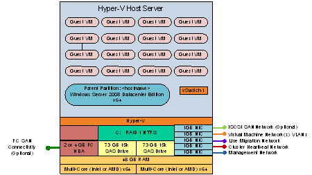
Figure 2: Cluster Host Server Overview
- Network Architecture
The Hyper-V servers within the environment will be connected to a number of different networks.
Each of the Cluster servers will be configured with up to 5 Networks:
- Management Network
- Virtual Machine Network
- Cluster Heartbeat network
- Live Migration Network (may be shared with Cluster Heartbeat Network if needed)
- Potentially an ISCSI network (if using an ISCSI SAN)
The Management connection is dedicated to the host itself for network I/O and management.
The Cluster heartbeat connection is used by all the cluster nodes to ascertain if all nodes within the cluster are responding and operational.
The Live migration network is used to failover virtual machines to alternate nodes in the cluster configuration with no loss of service to the end user.
The Virtual Machine network is dedicated to the guest virtual machines.
The ISCSI Network is used for connection to the ISCSI SAN (if used).
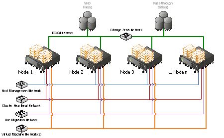
Figure 3: Cluster Node Network Overview
- Virtual Machine Networking
- Virtual Management Servers
The Virtualised Management Servers are pre-configured as follows:
Management Server | Machine Name | Host Network | VM Network | IP Address |
Active Directory Server | DDC1-DC01 | External Network 1 | Internal | 192.168.1.2 |
SCVMM Server | DDC1-SCVMM01 | External Network 1 | Internal | 192.168.1.5 |
SCOM Server | DDC1-SCOM01 | External Network 1 | Internal | 192.168.1.4 |
Web Portal Server | DDC1-WEB01 | External Network 1 | Internal | 192.168.1.6 |
Provisioning Server | DDC1-APF01 | External Network 1 | Internal | 192.168.1.3 |
Remote Desktop Gateway Server | DDC1-TSG01 | External Network 1 | Internal | 192.168.1.7 |
Firewall Server | DDC1-TMG01 | External Network 1 External Network 1 | DDC1 LAN External | 192.168.1.1 <External facing IP> |
Note: External Network 1 corresponds to the Virtual Machine Network in the Network Architecture
- New Virtual Machines
All new Virtual Machines will be built on the Host Cluster and be attached to External Network 1 (the Virtual Machine Network). They will also receive a DHCP address from the AD Server.
- User Access
The following user accounts have been created in the domain:
Domain\Username | Password |
| |
| |
| |
| |
And these have all been added to the following group:
- DDC1\Department Users
In SCVMM a new Self Service User Role has been created "Department Self Service Users" and the three department users have been added to this new role. The following rights have then been assigned:
- Scope – All Hosts
- VM Permissions – All Actions
- Create VM – No rights
- Store VM – No rights
On the TMG server, a Web Portal rule has been created to allow HTTP access for the users through to the DDC1-WEB01.ddc1.local server.
- G-Cloud Demonstrator Web site
On top of the G-Cloud Demonstrator infrastructure is the actual Web Site for provisioning and managing virtual machines. The capability being provided is as follows:
Managing Virtual Machines – the following options are available for managing machines:
- Start
- Stop
- De-Provision/Remove
- Connect to machine
Provisioning Virtual Machines – the following roles may be provisioned:
- Windows Server 2003 Base OS
- Windows Server 2008 R2 Base OS
- Red Hat Linux Base OS
- Windows Server 2008 R2 plus IIS Role
- Windows Server (supported version for Dynamics CRM)
- Windows Server (supported version for MOSS 2007)
- Windows Server 2008 R2 Base OS with Visual Studio 2010
Note: All Windows Servers have the username and password set to the following:
- Username: Administrator
- Password: Dynamic01!
Any Linux machines have the username and password set to:
- Username: root
- Password: pass@word1
- GCloud – Main Website
The GCloud website uses two configuration files which can be found in the following directory:
- C:\inetpub\wwroot\GCloud
- Web.Config
In the Web config file the following parameter which needs to be set for the proper functioning of the GCloud website as it designates the directory in which the log files are placed such that the Task Scheduler based "" task can collect the Cost Center and email address information for assigning to the virtual machine and initiating a notification email to the end-user once the machine provisioning is complete.
<appSettings>
<add key="provisioningLogsDirectory" value="c:\logs"/>
</appSettings>
- AvailableVMTypes.xml
In the GCloud Website directory there is also a file called AvailableVMTypes.xml, this can be changed to dynamically change the options found when attempting to provision a Virtual Machine through the GCloud demonstrator portal.
<?xml version="1.0" encoding="utf-8" ?>
<AvailableVMTypes>
<VMType
Name="Windows Server 2003 Base OS"
Template="Server 2003 Ent SP2 (x86)"
apfId="MS-BASE"/>
<VMType
Name="Windows Server 2008 R2 Base OS"
Template="Server 2008 R2 Ent (x64)"
apfId="MS-BASE"/>
<VMType Name="Windows Server 2008 R2 plus IIS Role" Template="Server 2008 R2 Ent (x64)" apfId="MS-IIS"/>
<VMType
Name="Windows Server (supported version for Dynamics CRM)"
Template="Server 2008 R2 Ent (x64)"
apfId="MS-DYN4"/>
<VMType
Name="Windows Server (supported version for MOSS 2007)"
Template="Server 2008 R2 Ent (x64)"
apfId="MS-MOSS2007"/>
<VMType
Name="Windows Server 2008 R2 plus Dev 10"
Template="Server 2008 R2 Ent (x64)"
apfId="MS-DEV2010"/>
<VMType Name="Red Hat Linux Base OS" Template="Redhat 5.3 (x64)" apfId=""/>
</AvailableVMTypes>
- VMM Service
The VMM Service uses two configuration files which can be found in the C:\inetpub\wwroot\VMMService directory:
- Web.Config
In the Web config file the following parameters are set for the proper functioning of Remote Control and the operation of the VMM Service itself:
<appSettings>
<add key="vmmServerName" value="ddc1-scvmm01.ddc1.local"/>
<add key="clientRDPPort" value=""/>
<!-- If this is set to 1 then the RDP ActiveX control will be supplied the rdpGateway settings shown below -->
<add key="rdpUseGateway" value="1"/>
<!-- Rdp ActiveX Gateway settings -->
<!-- See http://msdn.microsoft.com/en-us/library/aa381316(VS.85).aspx -->
<add key="rdpGatewayHostName" value="ddc1-tsg01.ddc1.local"/>
<add key="rdpGatewayUsageMethod" value="1"/>
<add key="rdpGatewayCredsSource" value="4"/>
<add key="rdpGatewayProfileUsageMethod" value="1"/>
</appSettings>
<client>
<endpoint address="http://ddc1-web01.ddc1.local/VMMService/VMMService.svc"
binding="basicHttpBinding" bindingConfiguration="BasicHttpBinding_IVirtualMachineManagerService"
contract="VMMService.IVirtualMachineManagerService" name="BasicHttpBinding_IVirtualMachineManagerService" />
</client>
- APF.XML
In the VMMService directory you will find a file called apf.xml which defines the details needed by the Provisioning engine:.
<MASTERAPF>
<CORELAB>
<DistUsr>APF_Source</DistUsr>
<DistPwd>Stimper12!</DistPwd>
<DistDom>DDC1</DistDom>
<APFSource>\\DDC1-APF01.DDC1.LOCAL\APFSrc</APFSource>
<APFTree>\\DDC1-APF01.DDC1.LOCAL\APFTree</APFTree>
<CompGrp>DDC1APF</CompGrp>
</CORELAB>
</MASTERAPF>
- Setting the Cost Center and SMTP Settings
A Powershell Script to set the Cost Center correctly in VMM and configure the SMTP settings is located on DDC1-WEB01.DDC1.LOCAL. The script can be found in the following location:
- D:\Scripts\SetParameters
In this folder there are two files:
- Config.xml
- SetParameters.ps1
- Config.XML
Config.xml holds the following configuration settings:
<CONFIG>
<VMMServer Name="DDC1-SCVMM01.DDC1.LOCAL" />
<ScriptDirectory Value="D:\Scripts\SetParameters" />
<BuildHost Value="\\DDC1-APF01.DDC1.LOCAL\APFTree" />
<BuildUsername Value="DDC1\administrator" />
<BuildPassword Value="Dynamic01!" />
<smtpserver Value="DDC1-WEB01.DDC1.LOCAL" />
<domain Value="DOMAINNAME" />
<Username Value="USERNAME" />
<Password Value="PASSWORD" />
<APFMon Value="http://DDC1-APF01.DDC1.LOCAL/APFMon/DDC1APF/1DayLogs.asp" />
<mailfrom Value="email@address.com" />
<EmailBcc Value="email@address.com" />
<logdir Value="C:\Logs\" />
<GCloudlogdir Value="C:\GCloud Logs\" />
<EmailFunctionality Value="No" />
<EmailCreds Value="No" />
</CONFIG>
Note: This config file is used by the SetParameters.ps1 script and should remain in the same directory as the script file.
If you wish to use the SMTP functionality you will need to specify the following values:
- SMTP Server – FQDN or IP address of SMTP Server or SMTP Relay – Currently DDC1-WEB01 is setup as a SMTP relay Server. To change the relay options locate the following:
- Internet Information Services (IIS) Manager – SMTP E-mail (From features View) and specify your SMTP Credentials
- If your SMTP Relay requires authentication then you must fill in the following field values:
- Domain
- Username
- Password
- Mailfrom – The email address the e-mail will be sent from
- EmailBcc – Email address to Bcc for archiving and Email verification
- There are 2 fields at the bottom of the config file for controlling the use of email and security:
- EmailFunctionality – toggles between two values
- No – EmailFunctionality is Disabled (Current Default)
- Yes – EmailFunctionality is Enabled
- EmailCreds – also toggles between two values
- No – Email credentials is not required (Current Default)
- Yes – Email credentials are required and will use values Domain, Username and Password from the configuration file.
- SetParameters.ps1
The SetParameters script does the following:
- Locates the Log directory that's stores created Virtual Machines from the GCloud Solution (Default is set to C:\Logs)
- Maps a drive to the APF Build Server so that it can gather build Status information.
- Gathers specific Variable information which includes:
- Virtual Machine Name($VMName)
- Email Address($Username)
- Virtual Host($VMHost)
- Cost Center Code($CC)
- Build($Build)
- Copies the log file to the GCloud log directory.
- Checks to see if the build is a linux build
- If a Linux build has been specified then the StartJob Function is called
- Uses the VM Name to check the status of the build from the build Server
- Tests the path to make sure the machines log file exists, if it doesn't script ends.
- If the path is true it then checks the status of the machine and looks for the tag "LogoffAtEnd"
- If LogoffAtEnd exists the StartJob Function is called
- The StartJob Function sets the cost center code for the specified Virtual Machine:
- Once set it deletes the log entry from the current build.
- If the Job completes successful the SendEmail function is called.
- Loops the script in case there is more than 1 entry.
- Set Parameters Scheduled Task
The script above runs as a Scheduled tasks on DDC1-WEB01.DDC1.LOCAL running under the DDC1\SVC_ProEng Account. The script currently runs every 15 minutes looking for log files in the log folder.
- Deploying G-Cloud Demonstrator
To deploy the G-Cloud Demonstrator into a new environment please follow the steps below:
- Provision one or more Windows 2008 R2 Hyper-V Host Servers to host the Virtual Management Servers.
- Ensure all these servers are on the same network and can communicate over a physical management network adapter.
- Next, create a Virtual Machine Network on each Hyper-V Host Server linked to a separate network adapter attached to the same VLAN called "External Network 1"
- Import the Virtual Management Servers into the Hyper-V Host Servers (as appropriate)
- Start up the machines and ensure that they come up ok and can communicate with each other over the network.
Note: All Administrator Account Passwords are set to "Dynamic01!"
- Build a new Hyper-V Cluster:
- Build at least two new Servers with Windows 2008 R2 Enterprise/Datacenter Edition
- Connect the networking up such that the following minimum connections are available:
- Management Network
- Heartbeat/Live Migration Network
- Adapter for Virtual Machine Network with a Virtual Network Name of "External Network 1"
- Join these servers to the DDC1 domain.
- Attached Storage to these servers.
- Cluster these machines.
- Create one or more Cluster Storage Volumes using the SAN storage
- Add the Cluster in DDC1-SCVMM01 so that it can be managed by SCVMM – Note: Ensure the Cluster is added into a new Host Group.
- Change the following configuration elements:
- DDC1-DC01 – Change the domain admin password
- All Management Servers – Change the local Administrator password
- DDC1-TMG01 – Check the access rule for external users and configure appropriately. Also change the web chaining rule to talk to your upstream proxy server.
- DDC1-APF01 – Run WSUS and synchronise the updates to make them available to the machines in the environment.
- DDC1-WEB01 – Change configuration files to reflect the environment – e.g. SMTP host, etc..
- User Accounts – either use existing DeptA/B/C accounts or rename appropriately
- Remote Desktop Gateway – this is currently setup to use a local certificate but in order to use that to connect you need to import it into the clients local Trusted Root Certificate Authority store. An alternate solution is to create another cert (with the correct computer name) from an existing Trusted Root Authority.
- Connect to http://ddc1-web01.ddc1.local/gcloud - from within the environment and check the website is up and running correctly. Then attempt the same from outside the DDC1 environment.
- Known Issues
- No limitations on the number of VMs that a user can request. Potential future enhancement.
- Cannot remote control a Linux machine currently (as there is no RDP connectivity). Potential to implement a telnet/X-Windows session instead in the future.
- No automatic SCOM agent install for provisioned Linux machines. Potential future enhancement to include the agent in the source.
- All Virtual machines are provisioned on same network and as such users can see all other machines on the network (but do not have logon access). Potential future enhancement to build VMs into separate VLANs but needs consideration of management infrastructure.
- Document Information
- Terms and Abbreviations
Abbreviation | Definition |
SCVMM | System Center Virtual Machine Manager |
SCOM | System Center Operations Manager |
VMM | Virtual Machine Manager |
WAN | Wide Area Network |
SAN | Storage Area Network |
SAS | Serial Attached SCSI |
TMG | Threat Management Gateway |
VHD | Virtual Hard disk |
VSV | Virtual save state file |
VSS | Volume shadow Copy Service |
Table 4: Terms and Abbreviations
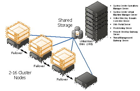
Appendix A – Hyper-V Host Server Farm Pattern
The Host Server Farm architecture pattern is illustrated below.
The architecture consists of a multi-node Windows Server 2008 R2 cluster leveraging a shared storage system such as an iSCSI or Fibre Channel storage area network (SAN) and storage array. Each node of the cluster runs Windows Server 2008 R2 with Hyper-V.
- This pattern provides server consolidation and high availability on a greater scale.
- Supports up to 16 nodes in a single cluster configuration.
- Virtual machines can run on any node of the cluster.
- In the event of a node failure, the virtual machines will be restarted automatically on any node that has the available capacity to host the failed resources.
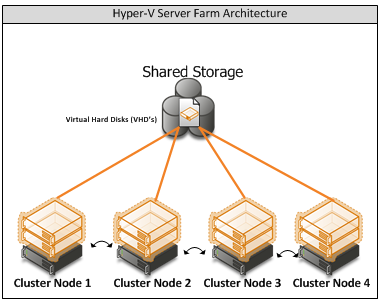
Figure 4: Hyper-V Server Farm pattern
Information
The Host Server Farm pattern provides high availability as well as better use of hardware since a single physical host can serve a passive node for up to 15 active nodes.
Appendix B – Host Cluster patterns
- No Majority – Disk Only
The cluster has quorum if one node is available and in communication with a specific disk in the cluster storage. Only the nodes that are also in communication with that disk can join the cluster.
Microsoft Recommendations
This pattern is not recommended for High Availability as the disk can be a single point of failure.
- Node Majority
Node Majority is a quorum model where each node that is available and in communication can vote. The cluster functions only with a majority of the votes, that is, more than half.
Microsoft Recommendations
This pattern is recommended in Failover Cluster deployments containing an odd number of nodes.
- Node and Disk Majority
Node and Disk Majority is a quorum model in Windows Server 2008 R2 Failover Clustering. In this quorum model, a cluster remains active until half of the nodes and its witness disk is available. In case, the witness disk is offline, a cluster requires a majority of nodes to be up and running in order to successfully run the cluster. This model contains two or more nodes connected to a shared storage device. The witness disk is stored on the cluster disk. This quorum model is used in scenarios where all nodes are connected to a shared storage device on the same network.
Microsoft Recommendations
This pattern is recommended in Failover Cluster deployments containing an even number of nodes.
- Node and File Share Majority
The file share witness feature is an improvement to the current Majority Node Set (MNS) quorum model. This feature lets you use a file share that is external to the cluster as an additional "vote" to determine the status of the cluster.
Microsoft Recommendations
This pattern is recommended in Failover Cluster deployments containing an even number of nodes and for Multi-Site failover clusters.
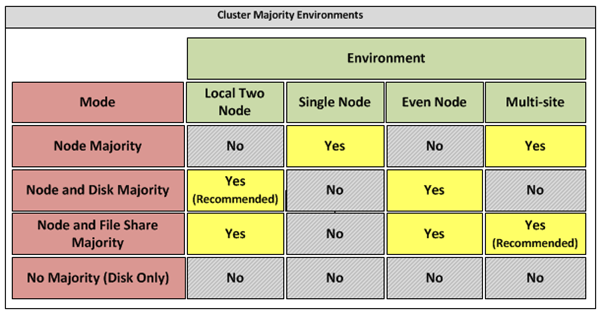
Figure 5: Host Cluster Patterns
Appendix C – Network Architecture
The network architecture of the host server is a frequently overlooked topic in host server sizing because Gigabit Ethernet NICs are now very inexpensive and most servers have at least two built in. The topic is important, however, because it is directly impacted by the host server architecture pattern selected. If one of the two host server cluster patterns is selected, a dedicated NIC per server is required for the cluster private (heartbeat) network. Gigabit Ethernet is a high-speed network transport, though a host server with a large number of guests may require greater than Gigabit speed, thus requiring additional NICs. Finally, it is recommended that each host server have a NIC dedicated to the host itself for network I/O and management.
A fairly large number of NICs per host server may be required. Recently, 10-Gigabit Ethernet has become commonly available and is starting to drift lower in price, similar to the way Gigabit Ethernet has done over the years. The ability for servers to utilize 10-Gigabit Ethernet NICs is a significant factor in increasing the consolidation ratio.
Microsoft Recommendations
Use multiple NICs and multi-port NICs on each host server.
- One NIC dedicated to the host machine only for management purposes
- One NIC dedicated to the private Cluster Heartbeat network
- One NIC dedicated to the Live Migration network
- One or more NICs dedicated to the guest virtual machines (use 10 gpbs NICS for highest consolidation)
- Two or more NICs dedicated to iSCSI with MPIO
Dedicate at least one NIC/Port on each host server for guest virtual machine network I/O. For maximum consolidation ratio, utilize one or more 10-Gigabit Ethernet NICs to virtual machine network I/O.
Warning
Microsoft does not support the use of NIC teaming software. Support for these third-party technologies must be provided by the vendor.
Appendix D - Processor Architecture
Windows Server 2008 R2 with Hyper-V requires x64 processor architecture from Intel or AMD, as well as support for hardware execute disable and hardware virtualization such as Intel VT or AMD-V.
Both Intel and AMD provide a wide range of processors that are appropriate for host servers. The industry competition between the two is very tight and at any one time; one may have a performance advantage over the other. Regardless of which manufacturer is chosen, several performance characteristics are important.
The number of processor cores is a key performance characteristic. Windows Server 2008 R2 with Hyper-V makes excellent use of multi-core processors, so the more cores the better. Another important characteristic is the processor clock speed, which is the speed at which all cores in the processor will operate. It's important because it will be the clock speed of all of the guest virtual machines. This is a key variable in the consolidation ratio because it impacts the amount of candidates that the host server can handle and the speed at which those guests will operate. As an example, choosing 2 GHz processor rather than a 3 GHz processor on a server that will host 20 guests means that all of those guests will run only at 2 GHz.
At a lower level of detail, the server processor architectures make design choices in terms of the type and quantity of processor cache, memory controller architecture, and bus/transport architecture. A detailed analysis of these factors is beyond the scope of this document.
Microsoft Recommendations
x64 processor architectures are required for all Hyper-V host server architecture patterns. If you are purchasing new servers, we recommend working with your server vendor to ensure that the selected hardware is capable of running Windows Server 2008 R2 and Hyper-V, and that it is validated for Windows Server 2008 R2 failover clustering. For new servers, we recommend selecting the maximum number of cores per processor available and choosing the fastest or second fastest clock speed available.
Appendix E – Memory Architecture
Once the system architecture and processor architecture choices are made, there are relatively few options remaining for memory architecture because it is usually predetermined by the manufacturer/system/processor combination. The memory architecture choices that remain are typically quantity, speed, and latency. For Hyper-V, the most important memory architecture choice is the quantity of RAM. Most consolidated workloads (that is, individual guest virtual machines) will require at least 512 MB to 1 GB of RAM or more. Since most commodity four-socket servers can only cost effectively support between 32 and 128 GB of RAM, this is frequently the limiting factor in host server capacity.
The quantity of RAM is a more important factor than RAM speed or latency. Once the maximum amount of RAM that is cost effective is determined, if there is a remaining choice between speed and latency, choosing the memory with lower latency is recommended.
Microsoft Recommendations
Given the system and processor architectures already selected, we recommend utilizing the maximum amount of RAM that can be cost effectively added to the host system. Typically, there is a price point where the cost of moving to the next DIMM size (that is, 2 GB DIMMs to 4 GB DIMMs) is more than twice the cost, and in some cases, it approaches the cost of an entire server. We recommend fully populating the server up to that price point. For example, if the server has 8 DIMM slots and 4 GB DIMMs are much more than twice the cost of 2 GB DIMMs, we recommend fully populating the server with 2 GB DIMMs and considering a second host server if additional capacity is required.
For all host server architecture patterns, we recommend a minimum of 16 GB of RAM.
For Multi-Node Host Server Farm patterns, we recommend a minimum of 64 GB per server.
Appendix F - Drive types
The type of hard drive utilized in the host server or the storage array the host servers will have a significant impact on the overall storage architecture performance. The critical performance factors for hard disks are the interface architecture (for example, U320 SCSI, SAS, SATA), the rotational speed of the drive (7200, 10k, 15k RPM), and the average latency in milliseconds. Additional factors, such as the cache on the drive, and support for advanced features, such as Native Command Queuing (NCQ), can improve performance. As with the storage connectivity, high IOPS and low latency are more critical than maximum sustained throughput when it comes to host server sizing and guest performance. When selecting drives, this translates into selecting those with the highest rotational speed and lowest latency possible. Utilizing 15k RPM drives over 10k RPM drives can result in up to 35% more IOPS per drive.
SCSI
SCSI drives are rapidly being replaced by SATA, SAS, and Fibre Channel drives. SCSI drives are not recommended for new host server architectures; however, existing servers with U320 SCSI drives can provide excellent performance characteristics.
SATA
SATA drives are a low cost and relatively high performance option for storage. SATA drives are available primarily in the 1.5 GB/s and 3.0 GB/s standards (SATA I and SATA II) with a rotational speed of 7200 RPM and average latency of around 4 ms. There are a few SATA I drives that operate at 10k RPM and average latency of 2 ms that can provide an excellent low cost storage solution.
SAS
SAS drives are typically much more expensive than SATA drives but can provide significantly higher performance in both throughput, and more importantly, low latency. SAS drives typically have a rotational speed of 10k or 15k RPM with an average latency of 2 to 3 ms.
Fibre Channel
Fibre Channel drives are usually the most expensive and typically have similar performance characteristics to SAS drives but use a different interface. The choice of Fibre Channel or SAS drives is usually determined by the choice of storage array. As with SAS, they are typically offered in 10k and 15k RPM variants with similar average latencies.
Microsoft Recommendations
Fibre Channel 15k RPM drives are recommended for Host Server Farm patterns.
If you are using a Fibre Channel SAN, ensure that the switch and director infrastructure is sized to handle the large amount of storage I/O that will be generated from the consolidated servers.
Appendix G - Disk Redundancy Architecture
Redundant Array of Inexpensive Disk (RAID) is strongly recommended for all Hyper-V host storage. By definition, Hyper-V hosts run and store data from multiple workloads. RAID is necessary to ensure that availability is maintained during disk failure. In addition, if properly selected and configured, RAID arrays can provide improvements in overall performance.
RAID 1
RAID 1 is disk mirroring. Two drives store identical information so that one is a mirror of the other. For every disk operation, the system must write the same information to both disks. Because dual write operations can degrade system performance, many employ duplexing, where each mirror drive has its own host adapter. While the mirror approach provides good fault tolerance, it is relatively expensive to implement because only half of the available disk space can be used for storage, while the other half is used for mirroring.
RAID 5
Also known as striping with parity, this level is a popular strategy for low- or mid-range storage systems. RAID 5 stripes the data in large blocks across the disks in an array. RAID 5 writes parity data across all the disks in the RAID 5 set. Data redundancy is provided by the parity information. The data and parity information is arranged on the disk array so that the two types of information are always on different disks. Striping with parity can offer better performance than disk mirroring (RAID 1). However, when a stripe member is missing, read performance is decreased (for example, when a disk fails). RAID 5 is a less expensive option because it utilizes drive space more efficiently than RAID 1.
RAID 1+0 (RAID 10)
For more information about these types of RAID systems, contact your storage hardware vendor.
RAID 1 or RAID 1+0 is recommended for the system volume in all host server architecture patterns.
RAID 1+0 is recommended for the data volumes in the Host Server Farm patterns.
Appendix H - Fibre Channel Storage Area Network
Architecture | Throughput (theoretical max Megabyte/sec) |
iSCSI (Gigabit Ethernet) | 125 MB/s |
Fibre Channel (2 GFC) | 212.5 MB/s |
SATA (SATA II) | 300 MB/s |
SCSI (U320) | 320 MB/s |
SAS | 375 MB/s |
Fibre Channel (4 GFC) | 425 MB/s |
Table 5: Comparison of Disk Controller throughput speeds
Appendix I - Disk Controller or HBA Interface
Architecture | Throughput (theoretical max Megabyte/sec) |
iSCSI (Gigabit Ethernet) | 125 MB/s |
Fibre Channel (2 GFC) | 212.5 MB/s |
SATA (SATA II) | 300 MB/s |
SCSI (U320) | 320 MB/s |
SAS | 375 MB/s |
Fibre Channel (4 GFC) | 425 MB/s |
Table 6: Comparison of Disk Controller Interfaces
4 GFC Fibre Channel is recommended for the Host Server Farm architecture pattern.
Appendix J - Cluster Shared Volumes
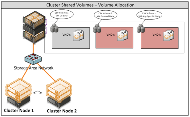
Figure 6: CSV Volume Allocation
Appendix K - System Center Virtual Machine Manager R2 2008
Virtual Machine Manager Server

 浙公网安备 33010602011771号