SONiC 之 testbed PTF简介
简介
PTF主要功能是通过收发包来验证DUT设备的转发面协议功能工作是否正常。
PTF是由OFTest继承而来,和OFTest不同在于PTF主要聚焦于转发面的测试框架。
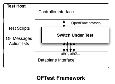
图 1. OFTest Framework
运行 PTF 所需软件:
- Python 2.7
- Scapy (recommend scapy-vxlan)
- pypcap (optional - VLAN tests will fail without this)
- tcpdump (optional - Scapy will complain if it's missing)
在SONiC Testbed中,PTF是以docker的形式运行在testbed server上,所以在搭建SONiC testbed之前,首先我们需要准备好PTF docker,并将它load进testbed server上。在整个testbed的测试中,PTF起到很大的作用,下面我们将结合testbed介绍PTF的相关功能,并解释其在testbed中的一些拓扑结构。
docker-ptf 编译
-
Build
docker-ptfimagegit clone --recursive https://github.com/Azure/sonic-buildimage.git cd sonic-buildimage make configure PLATFORM=vs ;#takes about 1 hour or more make target/docker-ptf.gz -
upload
docker-ptfto your registryclsnet@SDK-SONiC:~/george$ docker load -i docker-ptf.gz f14da82c36e2: Loading layer [==================================================>] 119.3MB/119.3MB 5e2c7951bac5: Loading layer [==================================================>] 1.724GB/1.724GB Loaded image: docker-ptf:latest clsnet@SDK-SONiC:~$ docker images REPOSITORY TAG IMAGE ID CREATED SIZE docker-ptf latest daeef4ab73fa 20 seconds ago 964MB clsnet@SDK-SONiC:~$ docker tag docker-ptf:latest localhost:5000/docker-ptf:latest clsnet@SDK-SONiC:~$ docker images REPOSITORY TAG IMAGE ID CREATED SIZE docker-ptf latest daeef4ab73fa About a minute ago 964MB localhost:5000/docker-ptf latest daeef4ab73fa About a minute ago 964MB clsnet@SDK-SONiC:~$ docker push localhost:5000/docker-ptf:latest The push refers to repository [localhost:5000/docker-ptf] f94269d57252: Pushed latest: digest: sha256:40482ca2f40bca4bc391ef79a22472f74a572bad26dd3cd5241a7cebfa7ced64 size: 529
如果没有本地仓库,使用如下命令创建本地仓库:
docker run -d -p 5000:5000 --name registry registry:2.7
具体docker仓库配置参考如下blog:
PTF端口类型
PTF的端口类型分为两类:直连口(direct port) 和 注入口(injected port)。
PTF with direct port
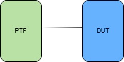
直连口就是DUT设备的面板口直接与PTF容器的端口相连。通常是PTF容器的eth0和DUT的Ethernet0相连,PTF的eth1和DUT的Ethernet4相连,依此类推。这种连接类型经常用于testbed PTF 拓扑以及T0 拓扑。
PTF with injected port
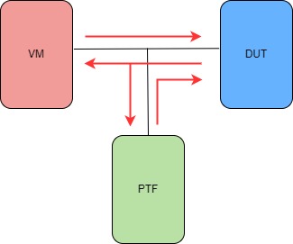
DUT的面板口和VMs的一个端口直连,但是与此同时PTF也挂载在这条连接上,报文从DUT物理端口可以同时发送给VMs和PTF docker。VM和PTF docker的报文都可以发送给DUT物理端口,这种连接方式允许我们通过PTF docker向VM和DUT之间的BGP域注入报文并验证报文,这种连接常用于testbed的T0及T1拓扑结构中。
这种连接的实现方式,是通过Open vSwitch 来实现,将VMs、PTF及DUT的端口连接到Open vSwitch上,通过配置Open vSwitch的规则,实现如上图红色箭头的报文转发规则。
testbed物理拓扑结构
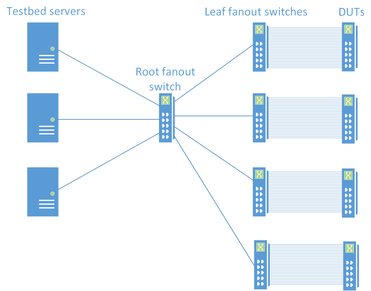
- DUT的端口和leaf fanout的端口一一对应相连
- 每个leaf fanout和DUT互连的端口,都会有一个唯一的vlan表示
- Root fanout用于连接leaf fanout和testbed server,root fanout不是必须的,简化的topo中,可以去掉root fanout,直接将leaf fanout的端口连接到testbed server上
- 和Root fanout的相连的端口,一般都是配置成802.1Q trunk口
- testbed server通过在报文中加入相应的vlan tag可以访问任意DUT的任何端口
testbed server的逻辑拓扑

在Testbed测试中,主要由DUT、FANOUT及testbed server组成,其中Fanout设备主要用于如上图所示的testbed server拓扑,在整个Testbed测试中,除了DUT外最重要的就是testbed server的拓扑配置,该拓扑主要包含VMs及PTF docker等模块,通过OVS及VLAN的划分,实现不同的testbed测试拓扑。
下面以testbed T0 拓扑结构为例,分别从management模块、back-plane模块已经PTF端口模式配置等方面,介绍PTF在其中所起的作用,通过本文的介绍,大家会对testbed如何管理PTF,bgp的实现,已经PTF端口模式的配置有一个大概的了解。
management port逻辑拓扑
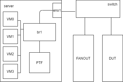
管理口是用来管理设备的通道,用户可以通过ssh等方式登录到设备上做一些操作。testbed server上是通过创建一个bridge,将VMs、 PTF以及server的management port添加到该bridge中实现相管理口互通。
br1             8000.6ab9a190c7c4       no              VM0300-m
                                                        VM0301-m
                                                        VM0302-m
                                                        VM0303-m
                                                        eno1
                                                        ptf-ptf1-m
拓扑结构如下图所示,每个VM有一个VMxxx-m的端口、PTF docker也有一个ptf-ptfx-m的端口,将这些端口和server的一个management端口绑定在一个bridge中,这样用户就可以通过server management端口访问所有的虚拟设备。
back-plane逻辑拓扑
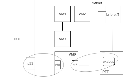
back-plane口之间的互联的主要用是实现VMs和PTF之间通过exabgp交换路由信息。同management port一样,也是将VMs和PTF的back-plane口加入一个bridge实现相互间通信,如下图所示。
br-b-ptf1               8000.8245a6e5194d       no      VM0300-back
                                                        VM0301-back
                                                        VM0302-back
                                                        VM0303-back
                                                        ptf-ptf1-b
进入ptf docker可以查看ptf上运行的exabgp服务:
root@6884a0fcd031:~# supervisorctl status
exabgp-ARISTA01T1                RUNNING   pid 118, uptime 2 days, 8:16:45
exabgp-ARISTA01T1-v6             RUNNING   pid 131, uptime 2 days, 8:16:42
exabgp-ARISTA02T1                RUNNING   pid 92, uptime 2 days, 8:16:53
exabgp-ARISTA02T1-v6             RUNNING   pid 105, uptime 2 days, 8:16:49
exabgp-ARISTA03T1                RUNNING   pid 66, uptime 2 days, 8:17:00
exabgp-ARISTA03T1-v6             RUNNING   pid 79, uptime 2 days, 8:16:57
exabgp-ARISTA04T1                RUNNING   pid 40, uptime 2 days, 8:17:07
exabgp-ARISTA04T1-v6             RUNNING   pid 53, uptime 2 days, 8:17:04
ptf_nn_agent                     RUNNING   pid 14, uptime 2 days, 10:35:21
sshd                             RUNNING   pid 13, uptime 2 days, 10:35:21
使用方法:
ptfhost.exabgp(name=k,
               state="started", \
               router_id = 10.0.0.1, \
               local_ip  = 10.0.0.1, \
               peer_ip   = 10.0.0.2, \
               local_asn = 65100, \
               peer_asn  = 65100, \
               port = 6000)
ptf direct port的逻辑拓扑
ptf和DUT端口对应关系由ptf docker中brcm_interface_to_front_map.ini文件配置,具体配置如下:
 brcm_interface_to_front_map.ini
 # ptf host interface @ switch front port name
 0@Ethernet0
 1@Ethernet4
 2@Ethernet8
 …………
 29@Ethernet116
 30@Ethernet120
 31@Ethernet124
具体是将端口配置成direct port 或者 inject port模式,是由testbed中ansible/vars/topo-xxx.yml文件中的配置决定,我们以T0拓扑为例,在该拓扑中,只定义了4个inject port,其它都市direct port。
topology:
  host_interfaces:
    - 0
    - 1
…………
    - 26
    - 27
  disabled_host_interfaces:
    - 0
    - 25
    - 26
    - 27
  VMs:
    ARISTA01T1:
      vlans:
        - 28
      vm_offset: 0
    ARISTA02T1:
      vlans:
        - 29
      vm_offset: 1
    ARISTA03T1:
      vlans:
        - 30
      vm_offset: 2
    ARISTA04T1:
      vlans:
        - 31
      vm_offset: 3
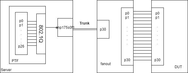
PTF端口和DUT的端口对应关系,如下图所示:
PTF docker 802.1Q info:
root@62960e1f493f:/# cat /proc/net/vlan/config
VLAN Dev name    | VLAN ID
Name-Type: VLAN_NAME_TYPE_RAW_PLUS_VID_NO_PAD
eth0           | 100  | enp175s0f1
eth1           | 101  | enp175s0f1
eth2           | 102  | enp175s0f1
eth3           | 103  | enp175s0f1
eth4           | 104  | enp175s0f1
eth5           | 105  | enp175s0f1
eth6           | 106  | enp175s0f1
eth7           | 107  | enp175s0f1
eth8           | 108  | enp175s0f1
eth9           | 109  | enp175s0f1
eth10          | 110  | enp175s0f1
eth11          | 111  | enp175s0f1
eth12          | 112  | enp175s0f1
eth13          | 113  | enp175s0f1
eth14          | 114  | enp175s0f1
eth15          | 115  | enp175s0f1
eth16          | 116  | enp175s0f1
eth17          | 117  | enp175s0f1
eth18          | 118  | enp175s0f1
eth19          | 119  | enp175s0f1
eth20          | 120  | enp175s0f1
eth21          | 121  | enp175s0f1
eth22          | 122  | enp175s0f1
eth23          | 123  | enp175s0f1
eth24          | 124  | enp175s0f1
eth25          | 125  | enp175s0f1
eth26          | 126  | enp175s0f1
ptf injected port的拓扑
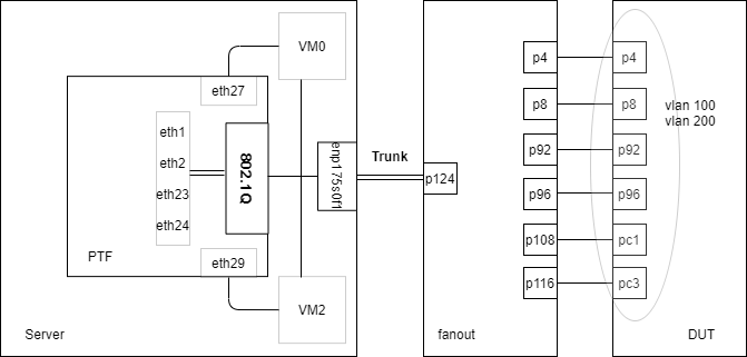
注入口相对于直连口要复杂一些,上面介绍PTF端口类型的时候有说过,injected port是通过Open vSwitch将PTF、VM及server Trunk口连接在一起,具体连接如下图所示:

查看server 上的802.1Q 信息:
clsnet@clsnet-PowerEdge-R540:~$ sudo cat /proc/net/vlan/config
[sudo] password for clsnet:
VLAN Dev name    | VLAN ID
Name-Type: VLAN_NAME_TYPE_RAW_PLUS_VID_NO_PAD
enp175s0f1.127 | 127  | enp175s0f1
enp175s0f1.128 | 128  | enp175s0f1
enp175s0f1.129 | 129  | enp175s0f1
enp175s0f1.130 | 130  | enp175s0f1
server上ovs bridge 信息如下,每个VM会创建一个bridge,将相应的端口加入进来,实现injected port功能。
clsnet@clsnet-PowerEdge-R540:~$ sudo ovs-vsctl show
51fa9729-7bc7-4225-87ce-f8bc845cf396
    Bridge "br-VM0300-0"
        Port "enp175s0f1.127"
            Interface "enp175s0f1.127"
        Port "VM0300-t0"
            Interface "VM0300-t0"
        Port "inje-ptf1-27"
            Interface "inje-ptf1-27"
        Port "br-VM0300-0"
            Interface "br-VM0300-0"
                type: internal
使用范例
利用vlan的一个testcase,具体解析一下ptf发包及收包验证的流程。
测试步骤
1、构建报文
首先,在ansible测试框架下,通过python脚本调用ptf库中封装的构包函数,封装一个以太网报文,示例代码如下所示。
import ptf.packet as scapy
import ptf.testutils as testutils
from ptf.mask import Mask

def build_icmp_packet(vlan_id, src_mac="00:22:00:00:00:02", dst_mac="ff:ff:ff:ff:ff:ff",
                         src_ip="192.168.0.1", dst_ip="192.168.0.2", ttl=64):

     pkt = testutils.simple_icmp_packet(pktlen=100 if vlan_id == 0 else 104,
                                 eth_dst=dst_mac,
                                 eth_src=src_mac,
                                 dl_vlan_enable=False if vlan_id == 0 else True,
                                 vlan_vid=vlan_id,
                                 vlan_pcp=0,
                                 ip_src=src_ip,
                                 ip_dst=dst_ip,
                                 ip_ttl=ttl)


pkt = build_icmp_packet(0)
         logger.info("Send untagged packet from {} ...".format(vlan_port["port_index"][0]))
         logger.info(pkt.sprintf("%Ether.src% %IP.src% -> %Ether.dst% %IP.dst%"))
2、发送报文
python脚本通过调用ptf中的send函数,将上一步封装的报文,从指定的port发往DUT设备处理。
def send(test, port_id, pkt, count=1):
3、验证报文
python脚本在发送完报文后通过使用ptf中dp_poll函数,在ptf中收包,poll指定端口是否收到和exp_pkt一致的报文,如收到表示测试成功,没有收到,则测试失败。
def dp_poll(test, device_number=0, port_number=None, timeout=None, exp_pkt=None):
vlan testcase 拓扑
dut vlan配置信息
admin@cel-silverstone-01:~$ show vlan brief
+--------+------------------+-----------------+----------+--------------+-------------+
|VLAN ID | IP Address       | Ports           | Port     | DHCP Helper  | Proxy ARP   |
|        |                  |                 | Tagging  |  Address     |             |
+========+==================+=================+==========+==============+=============+
|    100 | 192.168.100.1/24 | Ethernet0       | tagged   |              | disabled    |
|        |                  | Ethernet4       | untagged |              |             |
|        |                  | Ethernet8       | untagged |              |             |
|        |                  | Ethernet100     | tagged   |              |             |
|        |                  | PortChannel0001 | untagged |              |             |
|        |                  | PortChannel0003 | tagged   |              |             |
+--------+------------------+-----------------+----------+--------------+-------------+
|    200 | 192.168.200.1/24 | Ethernet0       | untagged |              | disabled    |
|        |                  | Ethernet4       | tagged   |              |             |
|        |                  | Ethernet8       | tagged   |              |             |
|        |                  | Ethernet100     | untagged |              |             |
|        |                  | PortChannel0001 | tagged   |              |             |
|        |                  | PortChannel0003 | untagged |              |             |
+--------+------------------+-----------------+----------+--------------+-------------+
|   1000 | 192.168.0.1/21   | Ethernet12      | untagged | 192.0.0.1    | disabled    |
|        | fc02:1000::1/64  | Ethernet16      | untagged | 192.0.0.2    |             |
|        |                  | Ethernet20      | untagged | 192.0.0.3    |             |
|        |                  | Ethernet24      | untagged | 192.0.0.4    |             |
|        |                  | Ethernet28      | untagged |              |             |
|        |                  | Ethernet32      | untagged |              |             |
|        |                  | Ethernet36      | untagged |              |             |
|        |                  | Ethernet40      | untagged |              |             |
|        |                  | Ethernet44      | untagged |              |             |
|        |                  | Ethernet48      | untagged |              |             |
|        |                  | Ethernet52      | untagged |              |             |
|        |                  | Ethernet56      | untagged |              |             |
|        |                  | Ethernet60      | untagged |              |             |
|        |                  | Ethernet64      | untagged |              |             |
|        |                  | Ethernet68      | untagged |              |             |
|        |                  | Ethernet72      | untagged |              |             |
|        |                  | Ethernet76      | untagged |              |             |
|        |                  | Ethernet80      | untagged |              |             |
|        |                  | Ethernet84      | untagged |              |             |
|        |                  | Ethernet88      | untagged |              |             |
|        |                  | Ethernet92      | untagged |              |             |
|        |                  | Ethernet96      | untagged |              |             |
+--------+------------------+-----------------+----------+--------------+-------------+
dut route配置信息
S>* 0.0.0.0/0 [200/0] via 10.250.0.1, eth0, weight 1, 01:50:35
C>* 10.1.0.32/32 is directly connected, Loopback0, 01:50:26
C>* 10.250.0.0/24 is directly connected, eth0, 01:50:37
K>* 100.1.1.2/32 [0/0] via 192.168.100.2, Vlan100, 00:00:10
K>* 100.1.1.4/32 [0/0] via 192.168.100.4, Vlan100, 00:00:09
K>* 100.1.1.5/32 [0/0] via 192.168.100.5, Vlan100, 00:00:11
K>* 100.1.1.8/32 [0/0] via 192.168.100.8, Vlan100, 00:00:08
K>* 100.1.1.10/32 [0/0] via 192.168.100.10, Vlan100, 00:00:07
K>* 100.1.1.23/32 [0/0] via 192.168.100.23, Vlan100, 00:00:10
C>* 192.168.0.0/21 is directly connected, Vlan1000, 01:50:16
C>* 192.168.100.0/24 is directly connected, Vlan100, 00:01:40
C>* 192.168.200.0/24 is directly connected, Vlan200, 00:01:38
K>* 200.1.1.2/32 [0/0] via 192.168.200.2, Vlan200, 00:00:10
K>* 200.1.1.4/32 [0/0] via 192.168.200.4, Vlan200, 00:00:09
K>* 200.1.1.5/32 [0/0] via 192.168.200.5, Vlan200, 00:00:11
K>* 200.1.1.8/32 [0/0] via 192.168.200.8, Vlan200, 00:00:08
K>* 200.1.1.10/32 [0/0] via 192.168.200.10, Vlan200, 00:00:08
K>* 200.1.1.23/32 [0/0] via 192.168.200.23, Vlan200, 00:00:11
