使用寄存器点亮LED——2
1. 项目:使用stm32寄存器点亮LED, 分别点亮红、绿、蓝3个灯。
2. 步骤
- 先新建个文件夹保存项目
- 再新建项目
- 将startup_stm32f10x_hd.s拷贝到该文件夹下
- 新建main.c子项目
- 再次在文件夹中新建stm32f10.h文件
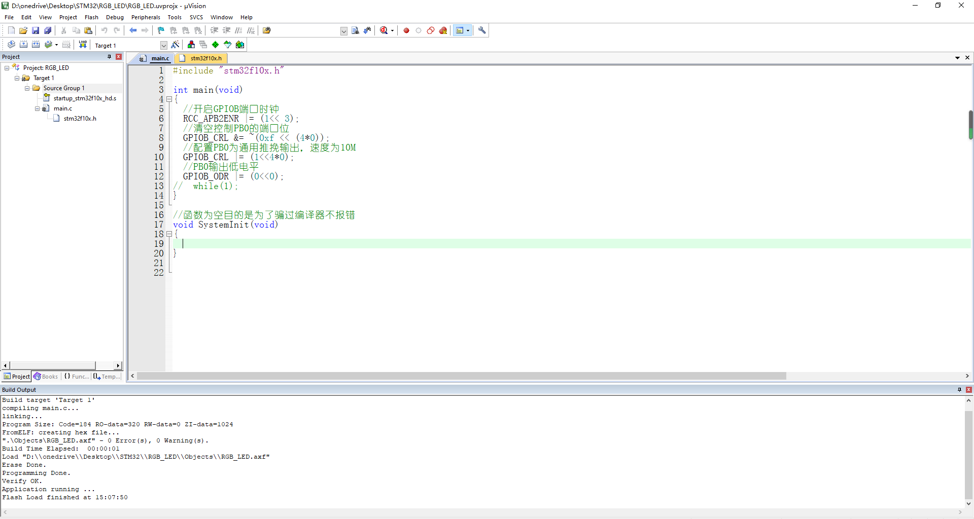
- 编写main.c,将stm32f10.h导入编译
- 编写stm32f10.h子项目
3. 代码
main.c
1 2 3 4 5 6 7 8 9 10 11 12 13 14 15 16 17 18 19 20 | #include "stm32f10x.h"int main(void){ //开启GPIOB端口时钟 RCC_APB2ENR |= (1<< 3); //清空控制PB0的端口位 GPIOB_CRL &= ~(0xf << (4*0)); //配置PB0为通用推挽输出,速度为10M GPIOB_CRL |= (1<<4*0); //PB0输出低电平 GPIOB_ODR |= (0<<0);// while(1);}//函数为空目的是为了骗过编译器不报错void SystemInit(void){ } |
stm32f10.h
1 2 3 4 5 6 7 8 9 10 11 12 13 14 15 16 17 18 19 20 21 22 23 24 25 26 27 | //列表3:代码清单:点亮LED-3外设地址定义/*片上外设基地址*/#define PERIPH_BASE ((unsigned int )0x40000000)/*总线基地址,GPIO 都挂载到APB2上*/#define APB2PERIPH_BASE (PERIPH_BASE + 0x10000)/*AHB系统总线,APB1,APB2总线都挂载到AHB系统总线上*/#define AHBPERIPH_BASE (PERIPH_BASE + 0x20000)/*GPIOB外设基地址*/#define GPIOB_BASE (APB2PERIPH_BASE + 0x0c00)/*GPIOB寄存器地址,强制转换成指针*/#define GPIOB_CRL *(unsigned int*)(GPIOB_BASE + 0x00)#define GPIOB_CRH *(unsigned int*)(GPIOB_BASE + 0x04)#define GPIOB_IDR *(unsigned int*)(GPIOB_BASE + 0x08)#define GPIOB_ODR *(unsigned int*)(GPIOB_BASE + 0x0c)#define GPIOB_BSRR *(unsigned int*)(GPIOB_BASE + 0x10)#define GPIOB_BRR *(unsigned int*)(GPIOB_BASE + 0x14)#define GPIOB_LCKR *(unsigned int*)(GPIOB_BASE + 0x18)/*RCC外设基地址*/#define RCC_BASE (AHBPERIPH_BASE + 0x1000)/*RCC的AHB1时钟使能寄存器地址,强制转换成指针*/#define RCC_APB2ENR *(unsigned int*)(RCC_BASE + 0x18) |
4. 这里我使用的时野火的指南者开发板,点亮的绿灯,如果需要点亮红蓝灯,只需要修改main.c 中的PB1, PB5端口设置即可。
5. 参考图片


分类:
stm32


【推荐】国内首个AI IDE,深度理解中文开发场景,立即下载体验Trae
【推荐】编程新体验,更懂你的AI,立即体验豆包MarsCode编程助手
【推荐】抖音旗下AI助手豆包,你的智能百科全书,全免费不限次数
【推荐】轻量又高性能的 SSH 工具 IShell:AI 加持,快人一步
· 基于Microsoft.Extensions.AI核心库实现RAG应用
· Linux系列:如何用heaptrack跟踪.NET程序的非托管内存泄露
· 开发者必知的日志记录最佳实践
· SQL Server 2025 AI相关能力初探
· Linux系列:如何用 C#调用 C方法造成内存泄露
· 震惊!C++程序真的从main开始吗?99%的程序员都答错了
· 【硬核科普】Trae如何「偷看」你的代码?零基础破解AI编程运行原理
· 单元测试从入门到精通
· 上周热点回顾(3.3-3.9)
· winform 绘制太阳,地球,月球 运作规律