树莓派图形编程(Python,C++,Scratch,BlockPi)Part.1 RGB灯间隔亮
爬虫最近搞不懂动了
为了毕设,开始弄一下树莓派
为了图方便,先摸了摸scratch图形编程,虽然自己也会C++和Python。
有图形编程在前,后面的就很好理解了,先开第一章,努力写好树莓派和传感器的日志(不敢说教程,太菜了)。
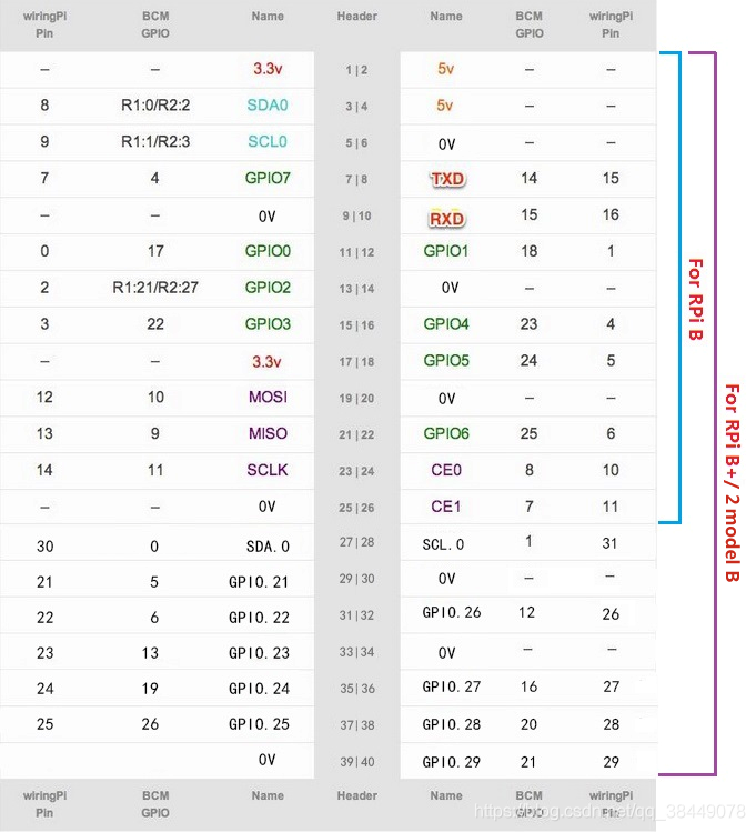
嵌入式第一条!针脚定义要知道
针脚定义图:

C++用得wiringPi模块,所以用的是wiringPi Pin对应的针脚;Scratch用的是BCM;Python有setmode()函数(这函数BCM和实际物理管脚定义都可以),所以我这里用Header那一列实际物理管脚给GPIO口就可以了。
这是本节用的接线方式,底下是个面包板,当然了,你可以选择直接每个杜邦线插在树莓派上对应的针脚也是一样的。
接线示意图:

没有扩展板的对应针管示意图:

LED灯图:

RGB分别接G17,G18,G27,GND接地(就是0V)(因为我这个转接板用得是BCM编码,所以我这里针脚号是BCM GPIO对应那一列号)。
1.Scratch

2.Python
(先按 Ctrl+C停止子函数的调用,再点程序停止,否则程序会直接关闭,忘了把所有针脚占空比改为0)
import RPi.GPIO as GPIO
import time

makerobo_pins = (11,12,13)  # PIN管脚字典

GPIO.setmode(GPIO.BOARD)     # 采用实际的物理管脚给GPIO口
GPIO.setwarnings(False)      # 去除GPIO口警告
GPIO.setup(makerobo_pins, GPIO.OUT)   # 设置Pin模式为输出模式
GPIO.output(makerobo_pins, GPIO.LOW)  # 设置Pin管脚为低电平(0V)关闭LED

p_R = GPIO.PWM(makerobo_pins[0], 2000)  # 设置频率为2KHz
p_G = GPIO.PWM(makerobo_pins[1], 2000)  # 设置频率为2KHz
p_B = GPIO.PWM(makerobo_pins[2], 2000)

# 初始化占空比为0(led关闭)
p_R.start(0)
p_G.start(0)
p_B.start(0)

def makerobo_set_Color():
	p_R.ChangeDutyCycle(100)     # 改变占空比
	time.sleep(0.5)
	p_R.ChangeDutyCycle(0)
	p_G.ChangeDutyCycle(100)     # 改变占空比
	time.sleep(0.5)
	p_G.ChangeDutyCycle(0)
	p_B.ChangeDutyCycle(100)     # 改变占空比
	time.sleep(0.5)
	p_B.ChangeDutyCycle(0)

# 调用循环函数
def makerobo_loop():
	while True:
		makerobo_set_Color()

# 释放资源
def makerobo_destroy():
	p_G.stop()
	p_R.stop()
	GPIO.output(makerobo_pins, GPIO.LOW)    # 关闭所有LED
	GPIO.cleanup()                          # 释放资源

# 程序入口
if __name__ == "__main__":
	try:
		makerobo_loop()       # 调用循环函数
	except KeyboardInterrupt:  # 当按下Ctrl+C时,将执行destroy()子程序。
		makerobo_destroy()    # 释放资源
3.C++
#include <wiringPi.h>
#include <softPwm.h>
#include <stdio.h>

#define uchar unsigned char

#define makerobo_Led_PinRed    0 // 红色LED 管脚
#define makerobo_Led_PinGreen  1 // 绿色LED 管脚
#define makerobo_Led_PinBlue   2 // 蓝色LED 管脚

// LED 初始化
void makerobo_led_Init(void)
{
	softPwmCreate(makerobo_Led_PinRed,  0, 100);
	softPwmCreate(makerobo_Led_PinGreen,0, 100);
	softPwmCreate(makerobo_Led_PinBlue, 0, 100);
}
// LED 颜色设置
void makerobo_led_Color_Set(uchar r_val, uchar g_val, uchar b_val)
{
	softPwmWrite(makerobo_Led_PinRed,   r_val);
	softPwmWrite(makerobo_Led_PinGreen, g_val);
	softPwmWrite(makerobo_Led_PinBlue,  b_val);
}

//-------------主程序-----------------
int main(void)
{
    //初始化连接失败时,将消息打印到屏幕
	if(wiringPiSetup() == -1){
		printf("setup wiringPi failed !");
		return 1;
	}
	makerobo_led_Init();

	while(1)
	{
		makerobo_led_Color_Set(0xff,0x00,0x00);   // 红色
		delay(500);                      // 延时500ms
		makerobo_led_Color_Set(0x00,0xff,0x00);   // 绿色
		delay(500);                      // 延时500ms
		makerobo_led_Color_Set(0x00,0x00,0xff);   // 蓝色
		delay(500);

		makerobo_led_Color_Set(0xff,0xff,0x00);   //黄色
		delay(500);                      // 延时500ms
		makerobo_led_Color_Set(0xff,0x00,0xff);   //pick
		delay(500);                      // 延时500ms
		makerobo_led_Color_Set(0xc0,0xff,0x3e);
		delay(500);                     // 延时500ms
4.BlockPi
这是一个比Scratch3还要强大的开源项目,图形化编程超级爽!
介绍和简单安装
以及
作者大大的知乎专栏
这个在你给完图形编程的同时,有对应的Python代码生成,多的我就不多赞述了,搭积木的快乐~
比Scratch内的树莓派模块强大很多
直接上图:

与之对应生成的代码:
from gpiozero import *
from colorzero import Color
import time

rgbled = None


rgbled = RGBLED(17, 18, 27)
rgbled.on()
for count in range(10):
  rgbled.color = Color('#ff0000')
  time.sleep(1)
  rgbled.color = Color('#009900')
  time.sleep(1)
  rgbled.color = Color('#3333ff')
  time.sleep(1)
  continue
rgbled.close()


