WebGL 光线追踪 Ray Tracing
Update:git地址 https://github.com/mahiru23/raytrace
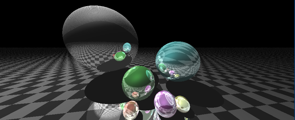
本文的根本目标是在WebGL中使用GLSL实现光线追踪,无图(懒得放了),仅供参考。
在一切开始之前,我们默认对GLSL的基本语法有所了解,不理解请自行查找。
一些需要重点关注的东西,请确认自己完全明白这一点再继续:
MVP变换:模型坐标空间 – 世界坐标空间 – 相机坐标空间 – 投影坐标空间。
在工作的时候一定要明白自己当前是在哪个坐标系下进行操作。
OpenGL 光线追踪其一:Phong光照模型
在渲染管线中,模型转换之后的工作就是Illumination(光照,这个过程我们也叫shading,着色)。简单来说,本阶段的工作就是对于光照的处理。
在计算机图形学中,对于光源,我们模拟的是光子(photon)。
一些物理概念:
albedo(反照率):衡量物体对光线的反射水平,the average reflectivity of the surface ornaments
flux(通量) : Radiation flux (electromagnetic flux, radiant flux)
Radiance(辐射) – radiant flux per unit solid angle per unit projected area,在图形学的角度上就是测量物体上某个点的反光量
Irradiance(辐照度) – differential flux falling onto differential area,理解为电磁辐射入射于曲面时每单位面积的功率
此处我们采用的Phong模型是BRDF反射模型,这一阶段我们单纯考虑反射,不考虑透明材质或次平面反射等。Phong光照模型在片元着色器中依赖于插值进行计算。
光源分为方向光源(平行光源不衰减)、点光源(随距离衰减)、面光源(蒙特卡洛法)等,本文基本采用单个点光源的方式进行处理,其他类型的光源暂时不考虑。
Phong光照模型
跳过繁杂的理论推导,我们直接从实现层面简单说明,Phong光照模型由以下三部分组成:
- Ambient:环境光源,不管什么遮挡/阴影等效果,所有位置都需要附上。在实际的视觉效果上提供基础照明,保证你不会得到一大片黑色。
- Specular Reflectance:镜面反射,在实际的视觉效果上提供高光,表现为物体表面的亮斑(如果有的话),一般在镜面材质上较强。
- Diffuse Reflectance:漫反射,一般是粗糙表面较多,在实际的视觉效果上表现为一大片晕染开的光。
最终得到的光照数值就是把以上三个光照加起来,简单粗暴,但是有效。
在此处,我们使用vec4类型的变量进行处理,最后一位没有实际意义,具体看个人实现。
假设n是平面法向量,l是光线方向,d是光源点到光照点的距离,v指向视点位置,r是反射后的光线。其中outNormal和outPosition从顶点着色器中传过来。Ambient/ diffuse/ specular为三个提前设定的光照参数,按需调整。
代码如下:
vec3 ads()
{
	vec3 n = outNormal;
    vec3 l = normalize(lightPositionCam - outPosition);
    float d = length(lightPositionCam - outPosition);
	vec3 v = normalize(-outPosition);
	vec3 r = reflect(-l, n);
    float lightIntensity = light/(4.0*3.1415926*d*d);
	vec4 res =  ambient +
                lightIntensity * (diffuse * max(dot(l, n), 0.0) +
                specular * pow(max(dot(r,v), 0.0), shininess));
    return vec3(res);
}
OpenGL 光线追踪其二:Texture纹理
在接下来的实际光线追踪中,我们期待能够让我们的玻璃球反射/折射出外部的贴图。
但如果你只关心如何实现光线追踪,而不考虑贴图效果,那么这一步可以跳过。
最简单的贴图只需要一张照片,使用六张照片构成一个Box,将我们的玻璃球放在其中。
请直接从这里:https://github.com/JoeyDeVries/LearnOpenGL 获取对应的texture资源。其中提供了很多基础的材质贴图和场景贴图。
将贴图应用到物体:如果是普通的model可以直接直接texture。如果你需要将一张贴图应用到球体/非实体平面/……等几何结构,或许需要做一些相应的几何变换以适应。
此外,一些其他的贴图(如凹凸贴图等)也进行了实现,此处暂不说明。
这是一个对于球体的典型贴图,textureSampler2自行导入:
uniform sampler2D textureSampler2;
intersec.colour = mix(thisSphere.colour, vec3(texture(textureSampler2,vec2(0.5+asin(intersec.normal.x)/(3.14),0.5-asin(intersec.normal.y)/(3.14)))), 0.5);
这个是对于平面的,这里直接使用了黑白格子:
if((modx<modbase/2.0 && modz<modbase/2.0) || (modx>=modbase/2.0 && modz>=modbase/2.0))
        intersec.colour = 1.0 - thisPlane.colour;
    else
        intersec.colour = thisPlane.colour;
OpenGL 光线追踪其三:反射(reflect)、折射(refract)和阴影(shadow)
光线追踪就是从视点出发,逆向查找投射进视点的光路。
这个过程是递归的,有对应的生成树,每一层都对应着反射(reflect)、折射(refract)和阴影(shadow)三个操作。
实际实现中大部分逻辑在片元着色器中实现。
第一步:求交点
这里我们只使用了球体和平面,
对于球体:显然,解线和球体相交的方程会有两个解,这里我们暂且称它们为u1和u2。这里我们只取u2,原因是我们这里不考虑一束光线在球体内部反复反射/折射,只有与u1相交的那个点才是合法的。
首先判断是否有交点(方程有解),已经交点是否合法(u1>0),在光线路径上而不是反向延长线上。之后取对应位置的贴图颜色。
Intersection sphereIntersection(vec3 p0, vec3 d, Sphere thisSphere) {

    Intersection intersec;
    vec3 ps = thisSphere.centre;
    float r = thisSphere.radius;
    vec3 delta_p = p0 - ps;
    float temp = pow(dot(d, delta_p), 2.0) - pow(length(delta_p), 2.0) + r*r;
    float u1 = -dot(d, delta_p) - sqrt(temp);
    float u2 = -dot(d, delta_p) + sqrt(temp);


    if((temp <= 0.001 || u1 <= 0.001)) {
        intersec.flag = false;
        return intersec;
    }

    // calculate the Intersection
    intersec.flag = true;
    intersec.u = u1;
    intersec.position = p0 + u1 * d;
    intersec.normal = normalize(intersec.position - ps);
    intersec.colour = thisSphere.colour;
    return intersec;
}
对于平面:与球体同理,但是只可能有一个交点,所以只需要取唯一的交点即可。
Intersection planeIntersection(vec3 p0, vec3 d, Plane thisPlane) {
    Intersection intersec;
    vec3 p1 = thisPlane.point;
    vec3 n = thisPlane.normal;
    float u = -dot(p0-p1, n)/dot(d, n);
    if(u <= 0.001) { // add offset to avoid self-shadowing
        intersec.flag = false;
        return intersec;
    }

    // calculate the Intersection
    intersec.flag = true;
    intersec.u = u;
    intersec.position = p0 + u * d;
    intersec.normal = n;
    float modbase = 1.0;
    float modx = mod(intersec.position.x, modbase);
    float modz = mod(intersec.position.z, modbase);

    // checkerboard pattern results even-odd cross grid
    if((modx<modbase/2.0 && modz<modbase/2.0) || (modx>=modbase/2.0 && modz>=modbase/2.0))
        intersec.colour = vec3(0.7, 0.7, 0.7);
    else
        intersec.colour = vec3(0.3, 0.3, 0.3);

    return intersec;
}
这里没有使用贴图,球体和平面均返回预设颜色。
第二步:找最近的交点
从第一步中返回的交点列表中选取最近的那个,若无交点则直接从该循环中返回。
            for(int i=0; i<sphere_num+1; i++) {
                if(intersectionList[i].flag == true) {
                    if(valid_flag == -1) {
                        closeIntersection = intersectionList[i];
                        min_u = intersectionList[i].u;
                        valid_flag = i;
                    }
                    else if(intersectionList[i].u < min_u) {
                        closeIntersection = intersectionList[i];
                        min_u = intersectionList[i].u;
                        valid_flag = i;
                    }
                    else {
                        ;
                    }
                }
            }

            if(valid_flag == -1) { // no valid intersection
                    Result[res_pos] = vec3(0.0);
                    res_pos++;
                    if(depth != maxRayTraceDepth-1) {
                        new_ray_list[now_list_size] = defalult_ray();
                        new_ray_list[now_list_size+1] = defalult_ray();
                        now_list_size += 2;
                    }
                    continue;
            }
第三步:检测阴影
阴影的检测方法是做该点与光源点的连线,检查中间是否有其他的物体,如果有则设为交点。
阴影仅考虑在单个点光源下的表现形式,不考虑多点光源带来的软阴影(soft shadow)问题。
// Shadow
bool shadow_check(Intersection intersection) {
    // slightly move the ray origin outwards of the object along the surface normal
    vec3 p0 = vec3(lightPosition);
    vec3 d = normalize(intersection.position - vec3(lightPosition));

    float u_this = length(intersection.position - vec3(lightPosition));

    float min_u = 100000.0;
    bool flag_sphere = false;
    for(int i=0; i<sphere_num; i++) {
        Intersection intersectionSphere = sphereIntersection(p0, d, sphere[i]);
        if(intersectionSphere.flag == true) {
            flag_sphere = true;
            min_u = min(min_u, intersectionSphere.u);
            //break;
        }
    }
    Intersection intersectionPlane = planeIntersection(p0, d, plane);
    if(intersectionPlane.flag == true) {
        min_u = min(min_u, intersectionPlane.u);
    }

    if(intersectionPlane.flag == false && flag_sphere == false) {
        return false;
    }

    if(min_u < u_this-0.001) {
        return true;
    }
    return false;
}
第四步:反射/折射
反射和折射可以用glsl的内置函数实现。需要注意的是,对于反射和折射的光线占比,可以根据物体折射率和光线角度,使用菲涅尔定律进行求解。
增加球体内部的反射和折射没什么必要,性能消耗过大了。
Ray Refract(Ray ray, Intersection intersection) {
    Ray new_ray;
    new_ray.p0 = intersection.position - intersection.normal*0.002; // another side
    new_ray.d = normalize(refract(ray.d, intersection.normal, 0.6));
    new_ray.intensity_k = ray.intensity_k*(1.0-k_fresnel);
    return new_ray;
}

Ray Reflect(Ray ray, Intersection intersection) {
    Ray new_ray;
    new_ray.p0 = intersection.position + intersection.normal*0.001;
    new_ray.d = normalize(reflect(ray.d, intersection.normal));
    new_ray.intensity_k = ray.intensity_k * k_fresnel;
    return new_ray;
}
图像效果

需要注意的问题:
在取交点的时候,记得沿法线外表面稍微延伸一小段距离(如0.001),否则由于浮点数精度丢失问题会出现粗糙表面。
在glsl中,由于该语言不支持递归,只能使用循环替代递归操作。因此需要使用额外的栈空间来进行过程中的中间值存储,并在完成后统一累加结果。
个人实际测试,递归到三层就会有很好的视觉效果,且光线追踪操作对于性能的消耗是随着生成树指数级递增的,因此尽量减少额外空间的使用(否则会爆显存),追踪3-4次即可,实测RTX2070的最大追踪深度在6-7层,谨慎使用过深。
final
毫无疑问这个实现效果是比较拉的,可以考虑增加菲涅尔效果/模糊阴影/抗锯齿超采样等等......理论确实是学了不少,但是限于工期,也不可能每一项都实现,毕竟也不打算从事图形学,只能说是丰富一下眼界罢了。
感谢看到这里,欢迎批评指正。


