Prj2:智能移动物体监测计数拍照记录设备
一、所需硬件:
STM32F103C8T6 / STM32F4。
OV2640 摄像头。
W25Q128 存储。
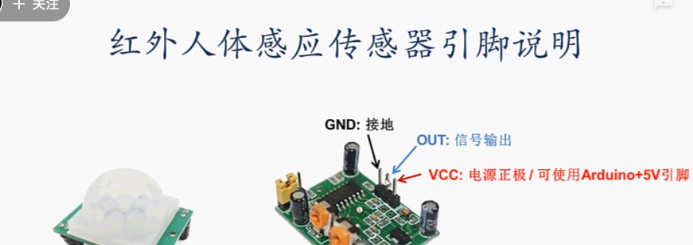
HC-SR501 人体红外感应模块。
蜂鸣器。
二、接线。
三、程序编写。
驱动代码编写。github使用。stm32 cubemx连接ov2640。ChatGPT对话开源。
Arduino Uno + 红外传感器HC-SR501 + 蜂鸣器 + 蓝牙模块返回最新数据:
 1 #include <EEPROM.h>  // 引入EEPROM库
 2 #include <SoftwareSerial.h>
 3
 4 SoftwareSerial bluetooth(0, 1);  // 设置蓝牙模块的软串口引脚
 5 // 红外传感器信号引脚
 6 const int irSensorPin = 7;
 7
 8 //红外传感器输出信号
 9 bool irSensorOutput;
10 const int buzzerPin = 3;  // 蜂鸣器的引脚
11 int motionCnt = 0;        // 存储移动物体的计数值
12
13 void setup() {
14   // 开启串口通信
15   Serial.begin(9600);
16   bluetooth.begin(9600);         // 初始化蓝牙软串口通信
17   // 设置红外人体感应模块的引脚为输入
18   pinMode(irSensorPin, INPUT);
19   Serial.println("irSensor ready!");
20   Serial.println("Bluetooth ready!");
21   // bluetooth.println("Bluetooth ready!");
22   motionCnt = EEPROM.read(0);    // 从EEPROM中读取计数值
23
24 }
25
26 void loop() {
27   // 读取红外人体感应模块的输出信号
28   irSensorOutput = digitalRead(irSensorPin);
29
30   // 打印检测结果
31   if (irSensorOutput == HIGH) {
32     motionCnt++;                   // 计数值自增1
33     Serial.print("Motion detected! ");
34     Serial.println(motionCnt);
35     pinMode(buzzerPin, OUTPUT);
36
37     if (motionCnt > 1000) {
38       Serial.println("Max 1000, back to zero");
39       motionCnt = 0;
40     }
41     EEPROM.write(0, motionCnt);  // 将计数值写入EEPROM
42     // bluetooth.print("OK: ");              // 发送"OK"给蓝牙设备
43     // bluetooth.println(motionCnt);
44     delay(1000);
45   } else {
46     pinMode(buzzerPin, INPUT);
47     // digitalWrite(buzzerPin, LOW);  // 关闭蜂鸣器
48   }
49   // 等待2s
50   delay(1000);
51 }
注意事项:
#1在Arduino的EEPROM中,每个字节都有一个独特的地址(从0到EEPROM大小-1)。EEPROM.read()函数用于读取指定地址上存储的数据,并将其转换为字节类型。
EEPROM的大小取决于Arduino板子的型号。例如,在Arduino Uno和Nano上,EEPROM的大小为1024字节,因此可以使用地址范围从0到1023的所有地址。
如果你想要读取或写入EEPROM中的数据,你需要了解你所使用的Arduino板子的EEPROM大小,并确保你所使用的地址不超出范围。
#2上电后蜂鸣器一直会响,无论高低电平,这时把蜂鸣器引脚设为输入模式(在此是无效模式,可暂停响声)pinMode(buzzerPin, INPUT);。
#3由于Arduino Uno板子只有一组硬串口(RX和TX引脚),当硬串口已经被占用时,不能再使用Serial.begin()函数进行初始化。
在这种情况下,可以使用SoftwareSerial库来创建一个软串口来与蓝牙模块进行通信。
请注意,使用软串口可能会导致通信速度较慢,因此可以尝试调整波特率和延时时间来优化通信效果。
作为从机的蓝牙模块也可以直接返回数据。首先,你需要确保你的蓝牙模块支持透明传输模式(Transparent Transmission Mode)。
在透明传输模式下,蓝牙模块会将从串口接收到的数据直接发送到主机设备,同时将主机设备发送的数据直接转发到串口输出。
STM32F103C8T6连接红外传感器HC-SR501:
 1 #include "stm32f4xx_hal.h"
 2
 3 #define PIR_GPIO_PORT   GPIOA
 4 #define PIR_GPIO_PIN    GPIO_PIN_0
 5
 6 void SystemClock_Config(void);
 7 static void MX_GPIO_Init(void);
 8
 9 int main(void)
10 {
11   HAL_Init();
12   SystemClock_Config();
13   MX_GPIO_Init();
14
15   while (1)
16   {
17     if(HAL_GPIO_ReadPin(PIR_GPIO_PORT, PIR_GPIO_PIN) == GPIO_PIN_SET)
18     {
19       // 运动检测到
20       // 在此处添加你的逻辑代码
21     }
22     else
23     {
24       // 没有运动检测到
25       // 在此处添加你的逻辑代码
26     }
27   }
28 }
29
30 void SystemClock_Config(void)
31 {
32   RCC_OscInitTypeDef RCC_OscInitStruct = {0};
33   RCC_ClkInitTypeDef RCC_ClkInitStruct = {0};
34
35   __HAL_RCC_PWR_CLK_ENABLE();
36   __HAL_PWR_VOLTAGESCALING_CONFIG(PWR_REGULATOR_VOLTAGE_SCALE1);
37
38   RCC_OscInitStruct.OscillatorType = RCC_OSCILLATORTYPE_HSI;
39   RCC_OscInitStruct.HSIState = RCC_HSI_ON;
40   RCC_OscInitStruct.HSICalibrationValue = RCC_HSICALIBRATION_DEFAULT;
41   RCC_OscInitStruct.PLL.PLLState = RCC_PLL_NONE;
42   if (HAL_RCC_OscConfig(&RCC_OscInitStruct) != HAL_OK)
43   {
44     Error_Handler();
45   }
46
47   RCC_ClkInitStruct.ClockType = RCC_CLOCKTYPE_HCLK | RCC_CLOCKTYPE_SYSCLK
48                               | RCC_CLOCKTYPE_PCLK1 | RCC_CLOCKTYPE_PCLK2;
49   RCC_ClkInitStruct.SYSCLKSource = RCC_SYSCLKSOURCE_HSI;
50   RCC_ClkInitStruct.AHBCLKDivider = RCC_SYSCLK_DIV1;
51   RCC_ClkInitStruct.APB1CLKDivider = RCC_HCLK_DIV1;
52   RCC_ClkInitStruct.APB2CLKDivider = RCC_HCLK_DIV1;
53   if (HAL_RCC_ClockConfig(&RCC_ClkInitStruct, FLASH_LATENCY_0) != HAL_OK)
54   {
55     Error_Handler();
56   }
57 }
58
59 static void MX_GPIO_Init(void)
60 {
61   GPIO_InitTypeDef GPIO_InitStruct = {0};
62
63   __HAL_RCC_GPIOA_CLK_ENABLE();
64
65   GPIO_InitStruct.Pin = PIR_GPIO_PIN;
66   GPIO_InitStruct.Mode = GPIO_MODE_INPUT;
67   GPIO_InitStruct.Pull = GPIO_PULLDOWN;
68   HAL_GPIO_Init(PIR_GPIO_PORT, &GPIO_InitStruct);
69 }
搞清楚C8T6调用程序和驱动程序的区别,理解上述代码。
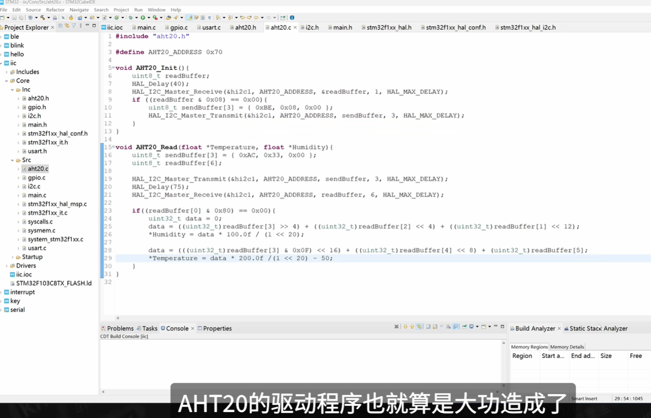
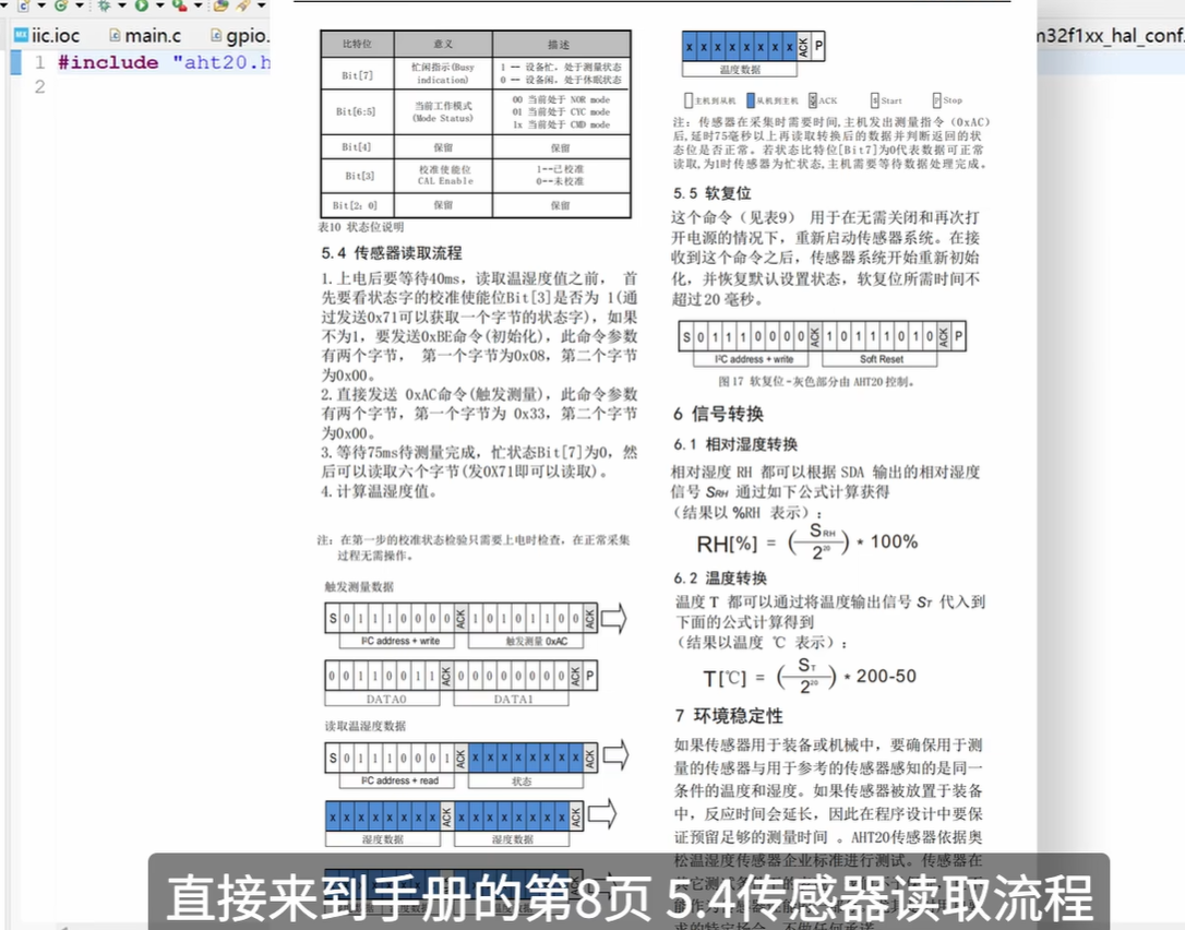
驱动程序实例(初始化以及读取AHT20温湿度传感器。)用什么传感器就对应数据手册写驱动程序
连接W25Q128。
连接OV2640。
这里C8T6没有DCMI接口。可能换为STM32F4含驱动源码板。
参考链接:
https://www.bilibili.com/video/BV1ae41167E6/?spm_id_from=333.337.search-card.all.click&vd_source=1c8d8b3756b33ac6eb1115e22c4073cd。(点亮OV2640摄像头的完整教程)
https://github.com/SimpleMethod/STM32-OV2640/。
https://zhuanlan.zhihu.com/p/669697776。
驱动源码:https://pan.baidu.com/s/19Tm1-7rWh6qeOVImOoBbXQ。
(简化版本):
1.移动物体监测。(serial.keysking.com,Web串口调试工具)
2.监测到高电平后每隔1秒,将时间和数据写入文件(高电平一直蜂鸣)。低电平不发数据。
