Q3a:FSM
1.Decade counter2.Four-bit binary counter3.Decade counter again4.Slow decade counter5.Counter 1-126.Counter 10007.4-digit decimal counter8.12-hour clock9.Hdlbits博文分布10.4-bit shift register11.Left/right rotator12.Left/right arithmetic shift by 1 or 813.5-bit LFSR14.3-bit LFSR15.32-bit LFSR16.Shift register17.Shift register(2)18.3-input LUT19.Rule 9020.Rule 11021.Conway's Game of Life 16x1622.Simple FSM1(asynchronous reset)23.Simple FSM1(synchronous reset)24.Simple FSM2(asynchronous reset)25.Simple FSM2(synchronous reset)26.Simple state transition 327.Simple one-hot state transition 328.Simple FSM 3(asynchronous reset)29.Simple FSM 3(synchronous reset)30.Design a Moore FSM31.Lemmings 132.Lemmings 233.Lemmings 334.Lemmings 435.One-hot FSM36.PS/2 packet parser37.PS/2 packet parser and datapath38.Serial receiver39.Serial receiver and datapath40.Serial receiver with parity checking41.Sequence recognition42.Q8:Design a Mealy FSM43.Q5a:Serial two's complementer(Moore FSM)44.Q5b:Serial two's complementer(Moore FSM)
45.Q3a:FSM
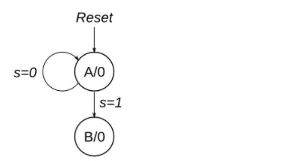
46.Q3b:FSM47.Q3c:FSM logic48.Q6b:FSM next-state logic49.Q6c:FSM next-state logic50.Q6:FSM51.Q2a:FSM52.Q2:One-hot FSM equations53.Q2a: FSM54.Q2b:Another FSM55.Counter with period 100056.4-bit shift register and down counter57.FSM:Sequence 1101 recognizer58.FSM:Enable shift register59.FSM:The complete FSM60.The complete timer61.FSM:One-hot logic equations62.UARTConsider a finite state machine with inputs s and w. Assume that the FSM begins in a reset state called A, as depicted below. The FSM remains in state A as long as s = 0, and it moves to state B when s = 1. Once in state B the FSM examines the value of the input w in the next three clock cycles. If w = 1 in exactly two of these clock cycles, then the FSM has to set an output z to 1 in the following clock cycle. Otherwise z has to be 0. The FSM continues checking w for the next three clock cycles, and so on. The timing diagram below illustrates the required values of z for different values of w.
Use as few states as possible. Note that the s input is used only in state A, so you need to consider just the w input.
考虑一个具有输入 s 和 w 的有限状态机。假设 FSM 以名为 A 的复位状态开始, 如下图所示。只要 s = 0,FSM 就会保持在状态 A,当 s = 1 时,它会移动到状态 B。一旦进入状态 B,FSM 就会在接下来的三个状态中检查输入 w 的值 时钟周期。如果 w = 1 恰好是其中两个时钟周期,则 FSM 必须在下一个时钟周期中将输出 z 设置为 1。否则,z 必须为 0。FSM 继续检查 w 接下来的三个时钟周期,依此类推。下面的时序图说明了所需的值 的 z 表示不同的 w 值。
使用尽可能少的状态。请注意,s 输入仅在状态 A 中使用,因此您只需要考虑 w 输入。
题目网站

module top_module (
    input clk,
    input reset,   // Synchronous reset
    input s,
    input w,
    output z
);
    parameter A=2'b00,B=2'b01,C=2'b10,D=2'b11;

    reg [1:0] state,next,count;

    always@(*)
        begin
            case(state)
                A:next = s ? B : A;
                B:next = C;
                C:next = D;
                D:next = B;
            endcase
        end

    always@(posedge clk)
        begin
            if(reset)
                state = A;
            else
                begin
                    if(state == A)
                        count = 2'b0;
                    else if(state == B)
                        count = w;
                    else
                        count = count + w;
                	state = next;
                end
        end

    always@(*)
        begin
            z = (state == B && count == 2);
        end
endmodule
自己写的在波形图不匹配,问题在于,希望在B状态进行复杂描述,反而出错。这里参考了CSDN上的一个写法。
CSDN网站
if(state == A)
                        count = 2'b0;
                    else if(state == B)
                        count = w;
                    else
                        count = count + w;
                	state = next;
这里的处理方法挺好的,是自己没有想到的,我是想用卡诺图实现,但没能成功。


【推荐】国内首个AI IDE,深度理解中文开发场景,立即下载体验Trae
【推荐】编程新体验,更懂你的AI,立即体验豆包MarsCode编程助手
【推荐】抖音旗下AI助手豆包,你的智能百科全书,全免费不限次数
【推荐】轻量又高性能的 SSH 工具 IShell:AI 加持,快人一步
· winform 绘制太阳,地球,月球 运作规律
· 震惊!C++程序真的从main开始吗?99%的程序员都答错了
· AI与.NET技术实操系列(五):向量存储与相似性搜索在 .NET 中的实现
· 超详细:普通电脑也行Windows部署deepseek R1训练数据并当服务器共享给他人
· 【硬核科普】Trae如何「偷看」你的代码?零基础破解AI编程运行原理