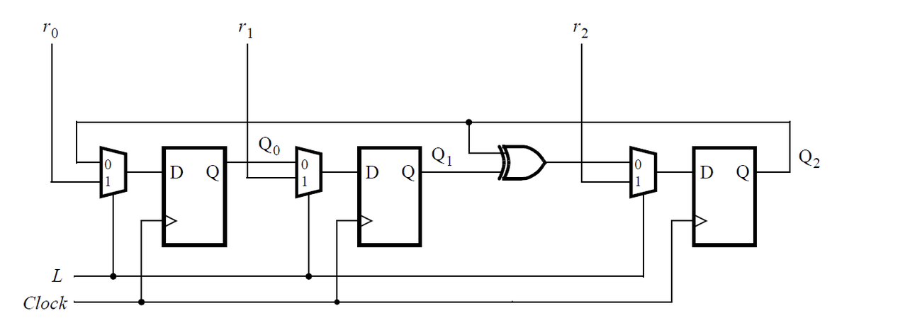
3-bit LFSR
1.Decade counter2.Four-bit binary counter3.Decade counter again4.Slow decade counter5.Counter 1-126.Counter 10007.4-digit decimal counter8.12-hour clock9.Hdlbits博文分布10.4-bit shift register11.Left/right rotator12.Left/right arithmetic shift by 1 or 813.5-bit LFSR
14.3-bit LFSR
15.32-bit LFSR16.Shift register17.Shift register(2)18.3-input LUT19.Rule 9020.Rule 11021.Conway's Game of Life 16x1622.Simple FSM1(asynchronous reset)23.Simple FSM1(synchronous reset)24.Simple FSM2(asynchronous reset)25.Simple FSM2(synchronous reset)26.Simple state transition 327.Simple one-hot state transition 328.Simple FSM 3(asynchronous reset)29.Simple FSM 3(synchronous reset)30.Design a Moore FSM31.Lemmings 132.Lemmings 233.Lemmings 334.Lemmings 435.One-hot FSM36.PS/2 packet parser37.PS/2 packet parser and datapath38.Serial receiver39.Serial receiver and datapath40.Serial receiver with parity checking41.Sequence recognition42.Q8:Design a Mealy FSM43.Q5a:Serial two's complementer(Moore FSM)44.Q5b:Serial two's complementer(Moore FSM)45.Q3a:FSM46.Q3b:FSM47.Q3c:FSM logic48.Q6b:FSM next-state logic49.Q6c:FSM next-state logic50.Q6:FSM51.Q2a:FSM52.Q2:One-hot FSM equations53.Q2a: FSM54.Q2b:Another FSM55.Counter with period 100056.4-bit shift register and down counter57.FSM:Sequence 1101 recognizer58.FSM:Enable shift register59.FSM:The complete FSM60.The complete timer61.FSM:One-hot logic equations62.UARTWrite the Verilog code for this sequential circuit (Submodules are ok, but the top-level must be named top_module). Assume that you are going to implement the circuit on the DE1-SoC board. Connect the R inputs to the SW switches, connect Clock to KEY[0], and L to KEY[1]. Connect the Q outputs to the red lights LEDR.
为此时序电路编写Verilog代码(子模块可以,但顶层必须命名为top_module)。假设您要在 DE1-SoC 板上实现该电路。将 R 输入连接到 SW 开关,将 Clock 连接到 KEY[0],将 L 连接到 KEY[1]。将 Q 输出连接到红灯 LEDR。

module top_module (
	input [2:0] SW,      // R
	input [1:0] KEY,     // L and clk
	output [2:0] LEDR);  // Q

    wire clk;
    assign clk = KEY[0];

    always @(posedge clk)begin
        if(KEY[1])begin
            LEDR[0] <= SW[0];
            LEDR[1] <= SW[1];
            LEDR[2] <= SW[2];
        end
        else begin
            LEDR[0] <= LEDR[2];
            LEDR[1] <= LEDR[0];
            LEDR[2] <= LEDR[2] ^ LEDR[1];
        end
    end

endmodule
再写:
首先是对上述写法的理解:
其实就是三个D触发器,只不过在d段对输入进行一个二分之一的选择,情况较为简单,可以直接将二分之一选择并入D触发器的代码
而且因为三个D触发器的选择都是由L来控制,所以可以一下控制三个,也即:
        if(KEY[1])begin
            LEDR[0] <= SW[0];
            LEDR[1] <= SW[1];
            LEDR[2] <= SW[2];
然后再提供一种先写子模块,然后实例化的写法,如下:
module top_module (
	input [2:0] SW,      // R
	input [1:0] KEY,     // L and clk
	output [2:0] LEDR);  // Q
    wire d21;
    assign d21=LEDR[1]^LEDR[2];

    little littleq0(.clk(KEY[0]),.d1(LEDR[2]),.d2(SW[0]),.l(KEY[1]),.q(LEDR[0]));
    little littleq1(.clk(KEY[0]),.d1(LEDR[0]),.d2(SW[1]),.l(KEY[1]),.q(LEDR[1]));
    little littleq2(.clk(KEY[0]),.d1(d21),.d2(SW[2]),.l(KEY[1]),.q(LEDR[2]));

endmodule

module little(
	input clk,
	input d1,
	input d2,
	input l,
    output q);
    wire d;
    assign d=(l)?d2:d1;
    always@(posedge clk)begin
        q<=d;
    end
endmodule
我自己的写法在命名上有些杂乱,但是只要抓住几个关键点即可:
input [1:0] KEY, // L and clk意思是L用KEY[0],clk用KEY[1]表示- 线稍微有些多,理清楚
合集:
Verilog学习


【推荐】国内首个AI IDE,深度理解中文开发场景,立即下载体验Trae
【推荐】编程新体验,更懂你的AI,立即体验豆包MarsCode编程助手
【推荐】抖音旗下AI助手豆包,你的智能百科全书,全免费不限次数
【推荐】轻量又高性能的 SSH 工具 IShell:AI 加持,快人一步
· winform 绘制太阳,地球,月球 运作规律
· 震惊!C++程序真的从main开始吗?99%的程序员都答错了
· AI与.NET技术实操系列(五):向量存储与相似性搜索在 .NET 中的实现
· 超详细:普通电脑也行Windows部署deepseek R1训练数据并当服务器共享给他人
· 【硬核科普】Trae如何「偷看」你的代码?零基础破解AI编程运行原理