Unity Shaderlab: Object Outlines
One of the simplest and most useful effects that isn’t already present in Unity is object outlines.
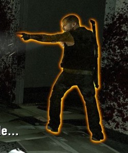 Screenshot from Left 4 Dead. Image Source:
http://gamedev.stackexchange.com/questions/16391/how-can-i-reduce-aliasing-in-my-outline-glow-effect
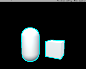
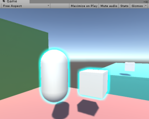
There are a couple of ways to do this, and the Unity Wiki covers one of these. But, the example demonstrated in the Wiki cannot make a “blurred” outline, and it requires smoothed normals for all vertices. If you need to have an edge on one of your outlined objects, you will get the following result:
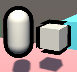 The WRONG way to do outlines
While the capsule on the left looks fine, the cube on the right has artifacts. And to the beginners: the solution is NOT to apply smoothing groups or smooth normals out, or else it will mess with the lighting of the object. Instead, we need to do this as a simple post-processing effect. Here are the basic steps:
- Render the scene to a texture(render target)
- Render only the selected objects to another texture, in this case the capsule and box
- Draw a rectangle across the entire screen and put the texture on it with a custom shader
- The pixel/fragment shader for that rectangle will take samples from the previous texture, and add color to pixels which are near the object on that texture
- Blur the samples
Step 1: Render the scene to a texture
First things first, let’s make our C# script and attach it to the camera gameobject:
using UnityEngine;
using System.Collections;

public class PostEffect : MonoBehaviour
{
    Camera AttachedCamera;
    publicShader Post_Outline;

    voidStart ()
    {
        AttachedCamera = GetComponent<Camera>();
    }

    voidOnRenderImage(RenderTexture source, RenderTexture destination)
    {

    }

}
OnRenderImage() works as follows: After the scene is rendered, any component attached to the camera that is drawing receives this message, and a rendertexture containing the scene is passed in, along with a rendertexture that is to be output to, but the scene is not drawn to the screen. So, that’s step 1 complete.
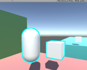
 Here’s the scene by itself
Step 2: Render only the selected objects to another texture
There are again many ways to select certain objects to render, but I believe this is the cleanest way. We are going to create a shader that ignores lighting or depth testing, and just draws the object as pure white. Then we re-draw the outlined objects, but with this shader.
//This shader goes on the objects themselves. It just draws the object as white, and has the "Outline" tag.

Shader "Custom/DrawSimple"
{
    SubShader
    {
        ZWrite Off
        ZTest Always
        Lighting Off
        Pass
        {
            CGPROGRAM
            #pragma vertex VShader
            #pragma fragment FShader

            structVertexToFragment
            {
                float4 pos:SV_POSITION;
            };

            //just get the position correct
            VertexToFragment VShader(VertexToFragment i)
            {
                VertexToFragment o;
                o.pos=mul(UNITY_MATRIX_MVP,i.pos);
                returno;
            }

            //return white
            half4 FShader():COLOR0
            {
                returnhalf4(1,1,1,1);
            }

            ENDCG
        }
    }
}
Now, whenever the object is drawn with this shader, it will be white. We can make the object get drawn by using Unity’s Camera.RenderWithShader() function. So, our new camera code needs to render the objects that reside on a special layer, rendering them with this shader, to a texture. Because we can’t use the same camera to render twice in one frame, we need to make a new camera. We also need to handle our new RenderTexture, and work with binary briefly.
Our new C# code is as follows:
using UnityEngine;
using System.Collections;

public class PostEffect : MonoBehaviour
{
    Camera AttachedCamera;
    publicShader Post_Outline;
    publicShader DrawSimple;
    Camera TempCam;
   // public RenderTexture TempRT;


    voidStart ()
    {
        AttachedCamera = GetComponent<Camera>();
        TempCam =new GameObject().AddComponent<Camera>();
        TempCam.enabled =false;
    }

    voidOnRenderImage(RenderTexture source, RenderTexture destination)
    {
        //set up a temporary camera
        TempCam.CopyFrom(AttachedCamera);
        TempCam.clearFlags = CameraClearFlags.Color;
        TempCam.backgroundColor = Color.black;

        //cull any layer that isn't the outline
        TempCam.cullingMask = 1 << LayerMask.NameToLayer("Outline");

        //make the temporary rendertexture
        RenderTexture TempRT =new RenderTexture(source.width, source.height, 0, RenderTextureFormat.R8);

        //put it to video memory
        TempRT.Create();

        //set the camera's target texture when rendering
        TempCam.targetTexture = TempRT;

        //render all objects this camera can render, but with our custom shader.
        TempCam.RenderWithShader(DrawSimple,"");

        //copy the temporary RT to the final image
        Graphics.Blit(TempRT, destination);

        //release the temporary RT
        TempRT.Release();
    }

}
Bitmasks
The line:
TempCam.cullingMask = 1 << LayerMask.NameToLayer("Outline");means that we are shifting the value (Decimal: 1, Binary: 00000000000000000000000000000001) a number of bits to the left, in this case the same number of bits as our layer’s decimal value. This is because binary value “01” is the first layer and value “010” is the second, and “0100” is the third, and so on, up to a total of 32 layers(because we have 32 bits up here). Unity uses this order of bits to mask what it draws, in other words, this is aBitmask.
So, if our “Outline” layer is 8, to draw it, we need a bit in the 8th spot. We shift a bit that we know to be in the first spot over to the 8th spot. Layermask.NameToLayer() will return the decimal value of the layer(8), and the bit shift operator will shift the bits that many over(8).
To the beginners: No, you cannot just set the layer mask to “8”. 8 in decimal is actually 1000, which, when doing bitmask operations, is the 4th slot, and would result in the 4th layer being drawn.
Q: Why do we even do bitmasks?
A: For performance reasons.
Moving along…
Make sure that at render time, the objects you need outlined are on the outline layer. You could do this by changing the object’s layer in LateUpdate(), and setting it back in OnRenderObject(). But out of laziness, I’m just setting them to the outline layer in the editor.
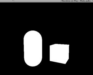 Objects to be outlined are rendered to a texture
The above screenshot shows what the scene should look like with our code. So that’s step 2; we rendered those objects to a texture.
Step 3: Draw a rectangle to the screen and put the texture on it with a custom shader.
Except that’s already what’s going on in the code; Graphics.Blit() copies a texture over to a rendertexture. It draws a full-screen quad(vertex coordinates 0,0, 0,1, 1,1, 1,0) an puts the texture on it.
And, you can pass in a custom shader for when it draws this.
So, let’s make a new shader:
Shader "Custom/Post Outline"
{
    Properties
    {
        //Graphics.Blit() sets the "_MainTex" property to the texture passed in
        _MainTex("Main Texture",2D)="black"{}
    }
    SubShader
    {
        Pass
        {
            CGPROGRAM

            sampler2D _MainTex;
            #pragma vertex vert
            #pragma fragment frag
            #include "UnityCG.cginc"

            struct v2f
            {
                float4 pos : SV_POSITION;
                float2 uvs : TEXCOORD0;
            };

            v2f vert (appdata_base v)
            {
                v2f o;

                //Despite the fact that we are only drawing a quad to the screen, Unity requires us to multiply vertices by our MVP matrix, presumably to keep things working when inexperienced people try copying code from other shaders.
                o.pos = mul(UNITY_MATRIX_MVP,v.vertex);

                //Also, we need to fix the UVs to match our screen space coordinates. There is a Unity define for this that should normally be used.
                o.uvs = o.pos.xy / 2 + 0.5;

                return o;
            }


            half4 frag(v2f i) : COLOR
            {
                //return the texture we just looked up
                return tex2D(_MainTex,i.uvs.xy);
            }

            ENDCG

        }
        //end pass
    }
    //end subshader
}
//end shader
If we put this shader onto a new material, and pass that material into Graphics.Blit(), we can now re-draw our rendered texture with our custom shader.
using UnityEngine;
using System.Collections;

public class PostEffect : MonoBehaviour
{
    Camera AttachedCamera;
    public Shader Post_Outline;
    public Shader DrawSimple;
    Camera TempCam;
    Material Post_Mat;
   // public RenderTexture TempRT;


    void Start ()
    {
        AttachedCamera = GetComponent<Camera>();
        TempCam = new GameObject().AddComponent<Camera>();
        TempCam.enabled = false;
        Post_Mat = new Material(Post_Outline);
    }

    void OnRenderImage(RenderTexture source, RenderTexture destination)
    {
        //set up a temporary camera
        TempCam.CopyFrom(AttachedCamera);
        TempCam.clearFlags = CameraClearFlags.Color;
        TempCam.backgroundColor = Color.black;

        //cull any layer that isn't the outline
        TempCam.cullingMask = 1 << LayerMask.NameToLayer("Outline");

        //make the temporary rendertexture
        RenderTexture TempRT = new RenderTexture(source.width, source.height, 0, RenderTextureFormat.R8);

        //put it to video memory
        TempRT.Create();

        //set the camera's target texture when rendering
        TempCam.targetTexture = TempRT;

        //render all objects this camera can render, but with our custom shader.
        TempCam.RenderWithShader(DrawSimple,"");

        //copy the temporary RT to the final image
        Graphics.Blit(TempRT, destination,Post_Mat);

        //release the temporary RT
        TempRT.Release();
    }

}
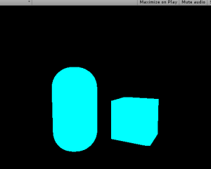
Which should lead to the results above, but the process is now using our own shader.
Step 4: add color to pixels which are near white pixels on the texture.
For this, we need to get the relevant texture coordinate of the pixel we are rendering, and look up all adjacent pixels for existing objects. If an object exists near our pixel, then we should draw a color at our pixel, as our pixel is within the outlined radius.
Shader "Custom/Post Outline"
{
    Properties
    {
        _MainTex("Main Texture",2D)="black"{}
    }
    SubShader
    {
        Pass
        {
            CGPROGRAM

            sampler2D _MainTex;

            //<SamplerName>_TexelSize is a float2 that says how much screen space a texel occupies.
            float2 _MainTex_TexelSize;

            #pragma vertex vert
            #pragma fragment frag
            #include "UnityCG.cginc"

            struct v2f
            {
                float4 pos : SV_POSITION;
                float2 uvs : TEXCOORD0;
            };

            v2f vert (appdata_base v)
            {
                v2f o;

                //Despite the fact that we are only drawing a quad to the screen, Unity requires us to multiply vertices by our MVP matrix, presumably to keep things working when inexperienced people try copying code from other shaders.
                o.pos = mul(UNITY_MATRIX_MVP,v.vertex);

                //Also, we need to fix the UVs to match our screen space coordinates. There is a Unity define for this that should normally be used.
                o.uvs = o.pos.xy / 2 + 0.5;

                return o;
            }


            half4 frag(v2f i) : COLOR
            {
                //arbitrary number of iterations for now
                int NumberOfIterations=9;

                //split texel size into smaller words
                float TX_x=_MainTex_TexelSize.x;
                float TX_y=_MainTex_TexelSize.y;

                //and a final intensity that increments based on surrounding intensities.
                float ColorIntensityInRadius;

                //for every iteration we need to do horizontally
                for(int k=0;k<NumberOfIterations;k+=1)
                {
                    //for every iteration we need to do vertically
                    for(int j=0;j<NumberOfIterations;j+=1)
                    {
                        //increase our output color by the pixels in the area
                        ColorIntensityInRadius+=tex2D(
                                                      _MainTex,
                                                      i.uvs.xy+float2
                                                                   (
                                                                        (k-NumberOfIterations/2)*TX_x,
                                                                        (j-NumberOfIterations/2)*TX_y
                                                                   )
                                                     ).r;
                    }
                }

                //output some intensity of teal
                return ColorIntensityInRadius*half4(0,1,1,1);
            }

            ENDCG

        }
        //end pass
    }
    //end subshader
}
//end shader
And then, if an object exists under the pixel, discard the pixel:
//if something already exists underneath the fragment, discard the fragment.
if(tex2D(_MainTex,i.uvs.xy).r>0)
{
    discard;
}
And finally, add a blend mode to the shader:
Blend SrcAlpha OneMinusSrcAlphaAnd the resulting shader:
Shader "Custom/Post Outline"
{
    Properties
    {
        _MainTex("Main Texture",2D)="white"{}
    }
    SubShader
    {
    Blend SrcAlpha OneMinusSrcAlpha
        Pass
        {
            CGPROGRAM

            sampler2D _MainTex;

            //<SamplerName>_TexelSize is a float2 that says how much screen space a texel occupies.
            float2 _MainTex_TexelSize;

            #pragma vertex vert
            #pragma fragment frag
            #include "UnityCG.cginc"

            struct v2f
            {
                float4 pos : SV_POSITION;
                float2 uvs : TEXCOORD0;
            };

            v2f vert (appdata_base v)
            {
                v2f o;

                //Despite the fact that we are only drawing a quad to the screen, Unity requires us to multiply vertices by our MVP matrix, presumably to keep things working when inexperienced people try copying code from other shaders.
                o.pos = mul(UNITY_MATRIX_MVP,v.vertex);

                //Also, we need to fix the UVs to match our screen space coordinates. There is a Unity define for this that should normally be used.
                o.uvs = o.pos.xy / 2 + 0.5;

                return o;
            }


            half4 frag(v2f i) : COLOR
            {
                //arbitrary number of iterations for now
                int NumberOfIterations=9;

                //split texel size into smaller words
                float TX_x=_MainTex_TexelSize.x;
                float TX_y=_MainTex_TexelSize.y;

                //and a final intensity that increments based on surrounding intensities.
                float ColorIntensityInRadius;

                //if something already exists underneath the fragment, discard the fragment.
                if(tex2D(_MainTex,i.uvs.xy).r>0)
                {
                    discard;
                }

                //for every iteration we need to do horizontally
                for(int k=0;k<NumberOfIterations;k+=1)
                {
                    //for every iteration we need to do vertically
                    for(int j=0;j<NumberOfIterations;j+=1)
                    {
                        //increase our output color by the pixels in the area
                        ColorIntensityInRadius+=tex2D(
                                                      _MainTex,
                                                      i.uvs.xy+float2
                                                                   (
                                                                        (k-NumberOfIterations/2)*TX_x,
                                                                        (j-NumberOfIterations/2)*TX_y
                                                                   )
                                                     ).r;
                    }
                }

                //output some intensity of teal
                return ColorIntensityInRadius*half4(0,1,1,1);
            }

            ENDCG

        }
        //end pass
    }
    //end subshader
}
//end shader
Step 5: Blur the samples
Now, at this point, we don’t have any form of blur or gradient. There also exists the problem of performance: If we want an outline that is 3 pixels thick, there are 3×3, or 9, texture lookups per pixel. If we want to increase the outline radius to 20 pixels, that is 20×20, or 400 texture lookups per pixel!
We can solve both of these problems with our upcoming method of blurring, which is very similar to how most gaussian blurs are performed.It is important to note that we are not doing a gaussian blur in this tutorial, as the method of weight calculation is different.I recommend that if you are experienced with shaders, you should do a gaussian blur here, but color it one single color.
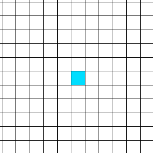
We start with a pixel:
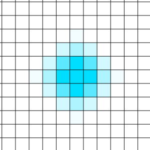
Which we can sample all neighboring pixels in a circle and weight them based on their distance to the sample input:
Which looks really good! But again, that’s a lot of samples once you reach a higher radius.
Fortunately, there’s a cool trick we can do.
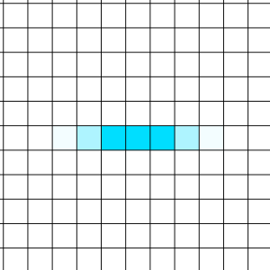
We can blur the texel horizontally to a texture….
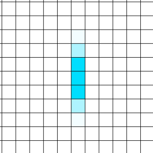
And then read from that new texture, and blur vertically…
Which leads to a blur as well!
And now, instead of an exponential increase in samples with radius, the increase is now linear. When the radius is 5 pixels, we blur 5 pixels horizontally, then 5 pixels vertically. 5+5 = 10, compared to our other method, where 5×5 = 25.
To do this, we need to make 2 passes. Each pass will function like the shader code above, but remove one “for” loop. We also don’t bother with the discarding in the first pass, and instead leave it for the second.
The first pass also uses a single channel for the fragment shader; No colors are needed at that point.
Because we are using two passes, we can’t simply use a blend mode over the existing scene data. Now, we need to do blending ourselves, instead of leaving it to the hardware blending operations.
Shader "Custom/Post Outline"
{
    Properties
    {
        _MainTex("Main Texture",2D)="black"{}
        _SceneTex("Scene Texture",2D)="black"{}
    }
    SubShader
    {
        Pass
        {
            CGPROGRAM

            sampler2D _MainTex;

            //<SamplerName>_TexelSize is a float2 that says how much screen space a texel occupies.
            float2 _MainTex_TexelSize;

            #pragma vertex vert
            #pragma fragment frag
            #include "UnityCG.cginc"

            struct v2f
            {
                float4 pos : SV_POSITION;
                float2 uvs : TEXCOORD0;
            };

            v2f vert (appdata_base v)
            {
                v2f o;

                //Despite the fact that we are only drawing a quad to the screen, Unity requires us to multiply vertices by our MVP matrix, presumably to keep things working when inexperienced people try copying code from other shaders.
                o.pos = mul(UNITY_MATRIX_MVP,v.vertex);

                //Also, we need to fix the UVs to match our screen space coordinates. There is a Unity define for this that should normally be used.
                o.uvs = o.pos.xy / 2 + 0.5;

                return o;
            }


            half frag(v2f i) : COLOR
            {
                //arbitrary number of iterations for now
                int NumberOfIterations=20;

                //split texel size into smaller words
                float TX_x=_MainTex_TexelSize.x;

                //and a final intensity that increments based on surrounding intensities.
                float ColorIntensityInRadius;

                //for every iteration we need to do horizontally
                for(int k=0;k<NumberOfIterations;k+=1)
                {
                    //increase our output color by the pixels in the area
                    ColorIntensityInRadius+=tex2D(
                                                    _MainTex,
                                                    i.uvs.xy+float2
                                                                (
                                                                    (k-NumberOfIterations/2)*TX_x,
                                                                    0
                                                                )
                                                    ).r/NumberOfIterations;
                }

                //output some intensity of teal
                return ColorIntensityInRadius;
            }

            ENDCG

        }
        //end pass

        GrabPass{}

        Pass
        {
            CGPROGRAM

            sampler2D _MainTex;
            sampler2D _SceneTex;

            //we need to declare a sampler2D by the name of "_GrabTexture" that Unity can write to during GrabPass{}
            sampler2D _GrabTexture;

            //<SamplerName>_TexelSize is a float2 that says how much screen space a texel occupies.
            float2 _GrabTexture_TexelSize;

            #pragma vertex vert
            #pragma fragment frag
            #include "UnityCG.cginc"

            struct v2f
            {
                float4 pos : SV_POSITION;
                float2 uvs : TEXCOORD0;
            };

            v2f vert (appdata_base v)
            {
                v2f o;

                //Despite the fact that we are only drawing a quad to the screen, Unity requires us to multiply vertices by our MVP matrix, presumably to keep things working when inexperienced people try copying code from other shaders.
                o.pos=mul(UNITY_MATRIX_MVP,v.vertex);

                //Also, we need to fix the UVs to match our screen space coordinates. There is a Unity define for this that should normally be used.
                o.uvs = o.pos.xy / 2 + 0.5;

                return o;
            }


            half4 frag(v2f i) : COLOR
            {
                //arbitrary number of iterations for now
                int NumberOfIterations=20;

                //split texel size into smaller words
                float TX_y=_GrabTexture_TexelSize.y;

                //and a final intensity that increments based on surrounding intensities.
                half ColorIntensityInRadius=0;

                //if something already exists underneath the fragment (in the original texture), discard the fragment.
                if(tex2D(_MainTex,i.uvs.xy).r>0)
                {
                    return tex2D(_SceneTex,float2(i.uvs.x,1-i.uvs.y));
                }

                //for every iteration we need to do vertically
                for(int j=0;j<NumberOfIterations;j+=1)
                {
                    //increase our output color by the pixels in the area
                    ColorIntensityInRadius+= tex2D(
                                                    _GrabTexture,
                                                    float2(i.uvs.x,1-i.uvs.y)+float2
                                                                                    (
                                                                                        0,
                                                                                        (j-NumberOfIterations/2)*TX_y
                                                                                    )
                                                    ).r/NumberOfIterations;
                }


                //this is alpha blending, but we can't use HW blending unless we make a third pass, so this is probably cheaper.
                half4 outcolor=ColorIntensityInRadius*half4(0,1,1,1)*2+(1-ColorIntensityInRadius)*tex2D(_SceneTex,float2(i.uvs.x,1-i.uvs.y));
                return outcolor;
            }

            ENDCG

        }
        //end pass
    }
    //end subshader
}
//end shader
And the final result:
Where you can go from here
First of all, the values, iterations, radius, color, etc are all hardcoded in the shader. You can set them as properties to be more code and designer friendly.
Second, my code has a falloff based on the number of filled texels in the area, and not the distance to each texel. You could create a gaussian kernel table and multiply the blurs with your values, which would run a little bit faster, but also remove the artifacts and uneven-ness you can see at the corners of the cube.
Don’t try to generate the gaussian kernel at runtime, though. That is super expensive.
I hope you learned a lot from this! If you have any questions or comments, please leave them below.



 浙公网安备 33010602011771号