RTT设备与驱动之I2C:
I2C主从结构(可以有多个主机,但同一时间只能有一个):I2C有两种地址结构7位/10位

总线空闲时,SDA 和 SCL 都处于高电平状态。
开始信号: SCL 为高电平时,主机将 SDA 拉低
结束信号: 在 SDA 为低电平时,主机将 SCL 拉高并保持高电平,然后在将 SDA 拉高,表示传输结束
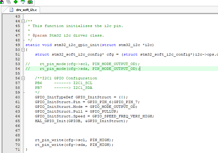
软件包:AT24CXX这个是IO模拟的I2C,可以同时模拟多个,但要注意的是:IO模拟时,管脚被配置成了OD输出不带上拉,此时必须有外部电阻上拉,否则是用不了的(可以用HAL接口函数代替);但若用硬件I2C,系统默认配置为复用推挽输出,可以设置内部上拉,还可以用。

API函数:
rt_device_t rt_device_find(const char* name);
rt_size_t rt_i2c_transfer(struct rt_i2c_bus_device *bus,
                          struct rt_i2c_msg         msgs[],
                          rt_uint32_t               num);
 struct rt_i2c_msg
{
  rt_uint16_t addr; /* 从机地址 */

  rt_uint16_t flags; /* 读、写标志等 */

  rt_uint16_t len; /* 读写数据字节数 */

  rt_uint8_t *buf; /* 读写数据缓冲区指针 */

}
读写寄存器示例:
struct rt_i2c_msg
{
  rt_uint16_t addr; /* 从机地址 */

  rt_uint16_t flags; /* 读、写标志等 */

  rt_uint16_t len; /* 读写数据字节数 */

  rt_uint8_t *buf; /* 读写数据缓冲区指针 */

}
读写寄存器示例:
#include <rtthread.h>
#include <rtdevice.h>

#define AHT10_I2C_BUS_NAME          "i2c1"  /* 传感器连接的I2C总线设备名称 */
#define AHT10_ADDR                  0x38    /* 从机地址 */
#define AHT10_CALIBRATION_CMD       0xE1    /* 校准命令 */
#define AHT10_NORMAL_CMD            0xA8    /* 一般命令 */
#define AHT10_GET_DATA              0xAC    /* 获取数据命令 */

static struct rt_i2c_bus_device *i2c_bus = RT_NULL;     /* I2C总线设备句柄 */
static rt_bool_t initialized = RT_FALSE;                /* 传感器初始化状态 */

/* 写传感器寄存器 */
static rt_err_t write_reg(struct rt_i2c_bus_device *bus, rt_uint8_t reg, rt_uint8_t *data)
{
    rt_uint8_t buf[3];
    struct rt_i2c_msg msgs;

    buf[0] = reg; //cmd
    buf[1] = data[0];
    buf[2] = data[1];

    msgs.addr = AHT10_ADDR;
    msgs.flags = RT_I2C_WR;
    msgs.buf = buf;
    msgs.len = 3;

    /* 调用I2C设备接口传输数据 */
    if (rt_i2c_transfer(bus, &msgs, 1) == 1)
    {
        return RT_EOK;
    }
    else
    {
        return -RT_ERROR;
    }
}

/* 读传感器寄存器数据 */
static rt_err_t read_regs(struct rt_i2c_bus_device *bus, rt_uint8_t len, rt_uint8_t *buf)
{
    struct rt_i2c_msg msgs;

    msgs.addr = AHT10_ADDR;
    msgs.flags = RT_I2C_RD;
    msgs.buf = buf;
    msgs.len = len;

    /* 调用I2C设备接口传输数据 */
    if (rt_i2c_transfer(bus, &msgs, 1) == 1)
    {
        return RT_EOK;
    }
    else
    {
        return -RT_ERROR;
    }
}
I2C的开发模式:硬件,软件模拟,设备驱动框架
I2C的开发模式:硬件,软件模拟,设备驱动框架


【推荐】国内首个AI IDE,深度理解中文开发场景,立即下载体验Trae
【推荐】编程新体验,更懂你的AI,立即体验豆包MarsCode编程助手
【推荐】抖音旗下AI助手豆包,你的智能百科全书,全免费不限次数
【推荐】轻量又高性能的 SSH 工具 IShell:AI 加持,快人一步
· .NET Core 中如何实现缓存的预热?
· 从 HTTP 原因短语缺失研究 HTTP/2 和 HTTP/3 的设计差异
· AI与.NET技术实操系列:向量存储与相似性搜索在 .NET 中的实现
· 基于Microsoft.Extensions.AI核心库实现RAG应用
· Linux系列:如何用heaptrack跟踪.NET程序的非托管内存泄露
· TypeScript + Deepseek 打造卜卦网站:技术与玄学的结合
· Manus的开源复刻OpenManus初探
· AI 智能体引爆开源社区「GitHub 热点速览」
· 三行代码完成国际化适配,妙~啊~
· .NET Core 中如何实现缓存的预热?
2018-01-15 三极管