WRF学习之 ch5 WRF模式(七)运行WRF(q-t)
q. WRF-Hydro
This is a new capability in V3.5. It couples WRF model with hydrology processes (such as routing and channeling). Using WRF-Hydro requires a separate compile by using environment variable WRF_HYDRO. In c-shell environment, do
setenv WRF_HYDRO 1
before doing ‘configure’ and ‘compile’. Once WRF is compiled, copy files from hydro/Run/ directory to your working directory (e.g. test/em_real/). A separately prepared geogrid file is also required. Please refer the following web site for detailed information: http://www.ral.ucar.edu/projects/wrf_hydro/. (From W. Yu)
r. Using IO Quilting
This option allows a few processors to be set aside to be responsible for output only. It can be useful and performance-friendly if the domain size is large, and/or the time taken to write an output time is becoming significant when compared to the time taken to integrate the model in between the output times. There are two variables for setting the option:
nio_tasks_per_group: How many processors to use per IO group for IO quilting.
Typically 1 or 2 processors should be sufficient for this purpose.
nio_groups: How many IO groups for IO. Default is 1.
*Note: This option is only used for wrf.exe. It does not work for real or ndown.
s. Using Physics Suites
Beginning in Version 3.9, an option to use physics suites was introduced. There are currently 2 available approved suites ("CONUS" and “tropical”) that require a one-line specification in namelist.input, and consist of a combination of physics options that have been highly tested and have shown good and reasonable results.
To use one of these options, simply set the "physics_suite" parameter in namelist.input, within the &physics namelist record, e.g.,
physics_suite = 'CONUS'
and this will set the packaged physics options for the chosen suite (specifically mp_physics, cu_physics, ra_lw_physics, ra_sw_physics, bl_pbl_physics, sf_sfclay_physics, and sf_surface_physics). At runtime, the model prints to the rsl files a summary of the physics schemes that will be used in the simulation, which are as follows (note: this is an example for a 2 domain run. All nests are assumed to use the same physics options unless the user specifically overrides these options - see example below):
physics_suite = 'tropical' physics_suite = 'CONUS'
mp_physics = 6, 6 mp_physics = 8, 8
cu_physics = 16, 16 cu_physics = 6, 6
ra_lw_physics = 4, 4 ra_lw_physics = 4, 4
ra_sw_physics = 4, 4 ra_sw_physics = 4, 4
bl_pbl_physics = 1, 1 bl_pbl_physics = 2, 2
sf_sfclay_physics = 91, 91 sf_sfclay_physics = 2, 2
sf_surface_physics = 2, 2 sf_surface_physics = 2, 2
It is possible to override any of the above options by simply adding that particular parameter to the namelist. For example, if you wish to use the CONUS suite but would like to turn off cu_physics for domain 3:
physics_suite = 'CONUS'
cu_physics = -1, -1, 0
If you wish to use CONUS suite but would like to use a different cu_physics option, and to turn cu_physics off for domain 3:
physics_suite = 'CONUS'
cu_physics = 2, 2, 0
t. Hybrid Vertical Coordinate
Beginning in Version 3.9, the option is available to use either a terrain following (TF) vertical coordinate (the vertical coordinate in the WRF model that has been used for the Eulerian mass model since the initial release) or a hybrid vertical coordinate (HVC). Here, the HVC is a coordinate that is terrain following near the ground and becomes isobaric at a pre-defined user level.
The new definition of the coordinate has been implemented with a modification to the meaning of the variable “mu”. Previously, this variable was both the 2d column pressure and the 2d d(PDRY)/d(h). With the selection of the hybrid vertical coordinate, now the dry pressure is defined as:
PDRY(i,j,k) = B(k) (PDRY SFC(i,j) – PTOP) + (h(k) – B(k)) (P0 – PTOP) + PTOP
where the B(k) field is a 1d weighting array computed internally.
When B(k) ≡ h(k), this definition simplifies to the current TF coordinate.
When B(k) ≡ 0, this definition simplifies to an isobaric coordinate system.
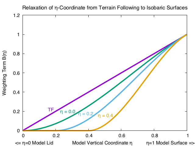
The vertical value where the B(k) arrays transitions to isobaric, hC, determines how many of the h layers (downward from the model lid) are isobaric. The default value for ETAC is set in a registry file, and is safe for usage across the globe. Figure 5.1 shows the transitioning of the coordinate surfaces from TF to HVC under several values of ETAC.

Description: relax_mono
Fig. 5.1 The transition of the h coordinate surfaces from terrain following (TF) to isobaric is a function of the critical value of h at which the user requests that an isobaric surface be achieved. The fundamental property of the TF vs. the HVC system is seen when tracing a horizontal line from any value on the “Weighting Term B(h)” axis. The degree of model coordinate “flatness”, for example, is the same in the TF system at h = 0.2 as in the HVC system for hC = 0.4 when the approximate value of h = 0.6.
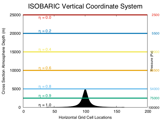
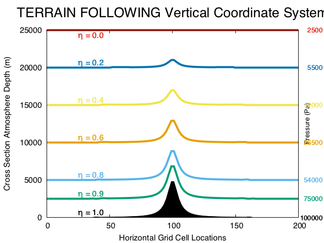
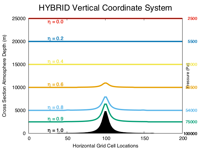
The depiction of the vertical location of an h surface for an isobaric coordinate (figure 5.2a), a terrain following coordinate (figure 5.2b), and a hybrid coordinate (figure 5.2c) is given with a simple 2d cross section. The depth of the atmosphere (m) is and the pressure are shown.

Description: xsect_isobaric

Description: xsect_tf

Description: xsect_hybrid
Fig. 5.2 Three cross section plots show the vertical location of the h surfaces for a given model lid (25 km is approximately 25 hPa) and for a given hC = 0.2.
This option becomes default in V4.0. Setting hybrid_opt = 0 option returns to the model to the full terrain-following coordinate.
It is important that the real.exe and the wrf.exe programs both run with the same hybrid_opt value.
The “mu” fields in the WRF model have changed meaning. Due to the large number of source lines that needed to modified, an automatic text processing method was chosen to introduce the changes. This automatic method is employed during the build process. Users are strongly warned against modifying any source code line that has any of the various “mu” arrays.
Users must also use care when pushing the HVC data through post-processors. The post-processors must know the new definition of dry pressure. It is preferable that either the hydrostatic pressure (P_HYD) or the total pressure (PB + P) be used for diagnostics and for vertical interpolations.
| 2021-01-12 16:46 | header |
|---|---|


 浙公网安备 33010602011771号