翻译:几何裁剪图下的使用嵌套的规则格网渲染地形
Geometry Clipmaps: Terrain Rendering Using Nested Regular Grids
几何裁剪图下的使用嵌套的规则格网渲染地形
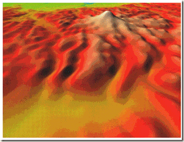
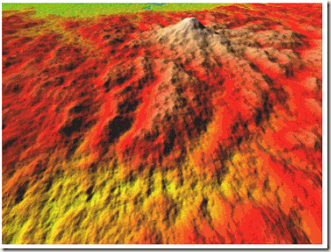
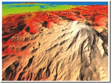
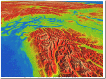
| 使用粗糙的geometry clipmap插图 (size n=31) | 216,000×93,600美国大峡谷附近观察图 (n=255) |
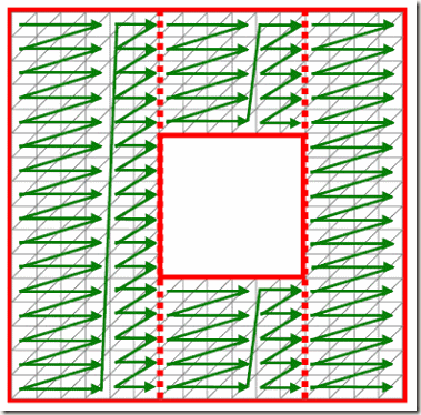
图1:使用geometry clipmaps的地形渲染, 展示clipmap各层次 (size n×n)以及过渡区域(右图蓝色)
摘要(Abstract )
渲染吞吐量已经达到能够用一种新的LOD(细节层次技术)去控制地形渲染的程度。我们介绍geometry clipmap,它能够通过一系列位于观察者中心的嵌套网格加速地形渲染。网格以顶点缓冲(vertex buffers)的形式存储在显示内存,当视点移动时不断地填充。这个简单的框架提供了可视的连贯性,帧约束(同一的帧速),complexity throttling,和graceful degradation。而且,它允许两种新的令人兴奋的实时功能特性: 解压缩(decompression)和合成(synthesis)。我们的主要数据是一个40GB的整个美国的高度图。一个压缩的图像金字塔使数据大小减少100倍。所以它完全适合在内存中。这压缩数据同样有助于法线图(normal map)的着色. 当观察者接近表面,我们通过分形噪声位移(fractal noise displacement)合成格网层次,比存储着的地形解压缩后要好。合成和normal-map计算是不断进行,因此使得我们能够以60帧每秒的速度交互飞行。
关键字(Keywords):细节层次控制(level-of-detail control)、地形压缩和综合(terrain compression and synthesis)
1、简介(Introduction)
地形几何是室外场景的一个重要组成部分,作为电影、虚拟环境、cartography、和游戏的实例。特别是对于室外游戏,包括飞行模拟、赛车模拟和大量多人游戏。在这篇文章,我们关注如何实时渲染地形高程。
大规模地形高度图包括十亿多的地形采样,离直接进行交互渲染还有很远的距离。此外,由于从象素抽样的未过滤的多对一映射,渲染统一的密集的三角形会导致混淆(aliasing)效果,正像没有多重映射(mipmap)的纹理。 [Williams 1983]。所以细节层次(LOD)控制对于调整地形tessellation是必须的,常以观察的参数作为因子。
在地形细节层次简化(LOD)方面已经有大量的研究,在第二节中我们将会回顾,过往的方案调整细分不但基于观察距离,还基于具体的地形几何。根据直觉我们可以看出,平坦的区域安排大的三角形,会带来更小三角形的不规则网格渲染。但是,这样的框架有几个缺点。细分准则和细分操作必须预计算,并且消耗额外的内存。数据结构设计会涉及带有不在同一个缓冲的随机存储访问。改变tessellation需要更慢的立即模式渲染,当对静态区域进行加速时会干扰时间的连续性。为了维持一致的帧速,细分阙值必须随着地形的起伏不平而改变。最终,表面着色需要纹理图形,它们分开存储用在整个不同的LOD结构上。
渲染吞吐量在现在的GPU上已经达到100M个三角形每秒,足够以视频速度基于象素大小地填充整个帧缓冲(framebuffer)。此外,顶点处理速度不断增加,接近象素处理速度,所以我们预测好的LOD策略不再是本质的,我们取而代之的是寻找所有三角形基于象素的地形的统一的屏幕。关键是开发一套LOD框架能够优化图形流水线的倚赖。
我们的贡献是geometry clipmap,它能以一系列以观察者为中心的嵌套网格加速地形渲染。这些网格而不同的power-of-two分辨率过滤的形式展现。并且以顶点缓冲的形式存储再显存。当观察者移动时,clipmap层次改变并且不断重新填充数据。
这个方法于与纹理映射中的图像LOD处理很类似。为了避免空间混淆(spatial aliasing),图像预过滤到一个power-of-two 网格的mipmap(多重映射)金子塔[Williams 1983]。Mipmap层次被渲染的每一个象素是屏幕空间参数微分的函数,倚赖于观察参数,不倚赖于图像内容。纹理裁剪图加速(cache)视点倚赖的Mipmap金字塔的子集 [Tanner et al 1998]。快速不断的纹理clipmap更新允许探索巨大的图像。
我们的几何裁剪图(geometry clipmaps)灵感来源于纹理裁剪图(texture clipmaps),但有一些关键的不同点。纹理裁剪图计算每个象素的LOD基于屏幕空间投影几何,但是对于地形,屏幕空间几何直到地形LOD选择前都不能获得——循环倚赖。更重要的是,每个象素的LOD选择会让保持网格密不透水和时间上的平滑变得困难。
取而代之,我们在世界空间基于观察距离选择LOD,使用一系列关于视点的嵌套的矩形区域。我们创建渐变区域以平滑和混合层次之间,使用0面积三角形缝补层次边界避免T-junctions。LOD过渡方案允许clipmap层次独立过渡,并且让各个层次裁剪胜于invalidated atomically像[Tanner et al 1998]表述。并且,我们应用一样的方案到纹理图像,获得统一的LOD框架对于几何和图像,并且不像纹理裁剪图,它不需要特别的硬件。
Geometry clipmaps提供了一系列的优点对于过往的地形LOD方案:
l 简单(Simplicity). 没有在基于指针/索引的结构上的不规则移动,并且没有细化倚赖的跟踪(tracking of refinement dependencies)。
l 优化的渲染吞吐量. Clipmap顶点存储在显示内存之中,并且它们的规则结构允许我们以带有优化顶点缓冲再用(with optimal vertex-cache reuse)的triangle-strip索引方式渲染。
l 可见的连贯性(Visual continuity ) 分别在顶点程序和象素程序使用一些指令,内部的层的渐变区域对于几何和纹理均提供空间和时间上的连贯性。
l 稳定的渲染(Steady rendering) 由于tessellation完全独立,不倚赖于地形粗糙度,无需参数用于动态调整,所以使得渲染速度接近常数。
• Immediate complexity throttling. 正因为有固定的clipmap大小,我们能够收缩渲染区域以减少渲染负荷。Tanner等[1998]使用一种近似的想法控制纹理裁剪图的更新带宽。
• Graceful degradation. 当观察者迅速移动的时候,更新带宽(重新填充clipmap)会变为瓶颈问题。就像在纹理裁剪图,我们更新尽可能多的层次在一次预算当中,这带来的结果是快速移动使地形丢失了它的高频细节。
l 表面着色(Surface shading). 法线图(Normal maps)在飞行时从几何体上方计算,并且使用一样的LOD结构作为地形几何。
地形几何同样提供两个新的运行时功能:
l 压缩(Compression).既然不单裁剪图需要扩展到顶点缓冲,剩余的地形金字塔也能够以压缩形式存储。我们通过二维的图像编码压缩金字塔各层之间差值(residuals),高的数据一致性允许我们压缩比达到60%—100%. 存储整个地形在内存中以避免磁盘分页停顿。
l 合成(Synthesis) 简单的规则格网结构允许我们on-the-fly地形合成,以便于粗糙的几何部分能够通过程序上生成细节得到增强。我们示范了简单的分形噪音,它可能在不久的将来能由GPU自己实现。
局限性(Limitations)
渲染网格比过往的LOD方案复杂。本质地,我们总是假设最差情况下的地形,带有同一的细节(每个地方有所有的频率),因此不利于局部调整。另一方面,网格是规则的,能够分配到显存。因而我们瞄准这种差的情况优化渲染渲染。
另外一个限制是地形被假设为像第9节所描述那样有边界频谱密度。举个例子,一个高的像针的特征地形会morph到观察范围比较迟。幸运的是,实际上地形是比较好和平滑的,不是十分常出现这种明显变化的问题。值得注意的是,建筑物、植物和其它对象被组合到环境上的,我们要使用其它LOD技术分别渲染
2. 过往的地形LOD技术(Previous terrain LOD techniques)
地形LOD算法使用层次网格细分合并操作以调整表面tessellation。算法能够根据结构分为下面这些:
l 不规则网格(Irregular meshes)
l 二叉树(Bin-tree hierarchies)
l 二叉区域(Bin-tree regions)
l 拼接块(Tiled blocks)
(4种过往的LOD方案详细介绍暂略)
理想化地,视点倚赖的LOD算法适应细化(分割)和粗糙化(合并)网格基于屏幕几何误差,几何误差被定义为以象素表示的网格和原地形点的距离。屏幕误差联合考虑影响来自下面个几个:(1)观察者距离(2)表面方位(3) 表面几何。既然表面方位很少提供重要的LOD影响,很多方案选择忽略它。一个通常的细分准则[Blow 2000]是每个顶点存储一个半径定义一个包围球。预计算半径编码了局部的表面近似误差,如果视点进入包围球则顶点的邻接顶点被细分。
几何裁剪图相当不同于过往这些工作。细分层次基于观察者为中心的规则格网,geomorph提供内部的连续性。这些细分准则仍然考虑观察者距离,但忽略局部几何。如:所有顶点共享一样的椭球半径。
视点倚赖的位移贴图映射(View-dependent displacement mapping)
地形能够被看成一个平坦的几何面上的位移图。一些最近的文献提出了硬件相关的方案用于调整位移贴图的tessellation [Gumhold and Hüttner 1999; Doggett and Hirche 2000; Moule and McCool 2002]。到目前为止,这些方案仅仅在简单的格网上模拟,并且他们假设整个格网是能容纳在内存的。
纹理(Textures) 到目前为止,没有很多工作关于如何处理伴随地形的巨大纹理图除了关于纹理裁剪图的[Tanner et al 1998],标准的方法是纹理拼接,还有更普通的纹理层次引入方案,如Döllner等[2000]。
根据我们的知识,没有过往的地形LOD技术能够达到有较大的压缩比和实现地形合成。
3. Geometry clipmap 概述
几何裁剪图(geometry clipmap),通过一系列m个层次构成一个地形金字塔, 以2n分辨率区域嵌套形式展现,如文章首部图1。每一个层次包含n×n个顶点的数组,存储在显存中的顶点缓冲。为了能够不断地进行有效更新,数组以环形(toroidally)方式编码,通过在x和y上的求模(mod)操作形成环形编码。每个顶点包含(x, y, z, zc)坐标,zc 是下一个粗糙层次的高度值(x, y),用于几何渐变。(6.2节)。
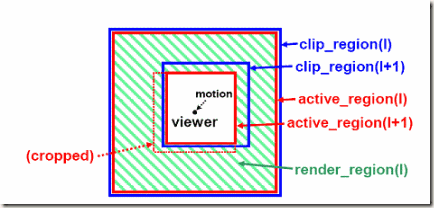
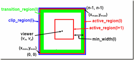
图2:geometry clipmap各区域定义
Clipmap regions
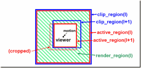
对于每一个clipmap层次,我们定义一系列矩形区域(见图2)。裁剪区域(clip region)是世界空间范围内每一层存储的n×n规则格网数据。活动区域(active region)是期望渲染的区域,特定为一个n×n区域位于观察者中心。当观察者移动时,我们通过裁剪区域(clip region)更新每一层匹配期望的活动区域的clipmap。但是,这样的更新在快速移动时是很耗费的,我们让裁剪区域(clip region)落后于观察者,并且裁剪活动区域(active region)到现有数据范围,如图2。最终,渲染区域(render region)被设计成空心的(图中绿色部分),它的外部边界是l层活动区域(active_region(l)),内部边界是l+1层活动区域(active_region(l+1))。
对于最好的m层,m+1层活动区域(active_region(m+1)),被定义为空,即最高层为实心方形区域。活动和裁剪区域在观察参数改变时更新,如第4节和第5节描述。
纹理(Vertex Shader Texture)
每一个clipmap层次同样包含关联的纹理图像。我们为每一个用到的表面存储一个8位每通道(8-bit-per-channel)的法线纹理图像,这比每个顶点(per-vertex)存储法线有效。对于可靠的着色,法线图(normal map)有相对于几何结构两倍的分辨率,即为几何格网两倍大小,因为一个顶点一个法线太模糊了 [Vlachos et al 2001]。法线图 (normal map)通过地形几何在clipmap更新的时候计算。额外的图像,如地形每个顶点的颜色属性同样可以存储为不同的分辨率。就像顶点数组,纹理也是以环形编址(toroidally)的方式以有效地更新。在现代GPU中,通常以Vertex Shader Texture Fetch(在顶点着色程序段访问纹理)实现。
每一帧的算法(Per-frame algorithm)
下面步骤是每一帧都要做的:
1. 检测期望的活动区域 (第4部分).
2. 更新地形几何 (第5部分).
3. 裁剪活动区域到裁剪区域(clip regions),并且渲染(第6部分)
4. 期望的活动区域运动的计算(Computation of desired active regions motion)
视点倚赖的refinement,通过clipmap 中每一层的活动区域选择被检测。我们通过一个简单的策略,对于在世界空间中格网间距为![]() 的每一层L,我们让期望的活动区域为以视点坐标(x,y)为中心的n×n区域。换句话,期望的clipmap被定位到观察者中心,我们希望渲染每一层的全部区域。
的每一层L,我们让期望的活动区域为以视点坐标(x,y)为中心的n×n区域。换句话,期望的clipmap被定位到观察者中心,我们希望渲染每一层的全部区域。
让我们考虑屏幕空间三角形大小和clipmap大小n之间的关系。我们假设地形有很小的坡度,所以每一个三角形近似一个大小为![]() 的直角三角形。(我们在第九节提供一个大致的误差分析)
的直角三角形。(我们在第九节提供一个大致的误差分析)
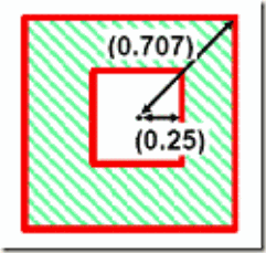
对于任意的可见的世界空间的点,屏幕大小反比例于屏幕空间的深度。如果视线方向是水平的,屏幕深度可以在XY平面量度。观察者坐落于l层渲染区域(render_region(l))的中心,它有n×![]() 的外边界大小,以及n×
的外边界大小,以及n×![]() /2的内边界大小。对于90度宽的视野,屏幕空间平均深度(遍及各个方向)大约0.4×n×
/2的内边界大小。对于90度宽的视野,屏幕空间平均深度(遍及各个方向)大约0.4×n×![]() 。所以近似的屏幕空间以象素表示的三角形大小s如下:
。所以近似的屏幕空间以象素表示的三角形大小s如下:
W是窗口大小,![]()
![]() ,我们定义W=640象素,
,我们定义W=640象素,![]() =90度,我们获得clipmap大小n=255的好结果。这符合一个屏幕空间三角形3象素的大小。所以我们的法线图(normal maps)以两倍于地形几何格网的分辨率存储。这给我们近似1.5象素每个纹理抽样(sample),对于纹理抽样设置来说是合情合理的。
=90度,我们获得clipmap大小n=255的好结果。这符合一个屏幕空间三角形3象素的大小。所以我们的法线图(normal maps)以两倍于地形几何格网的分辨率存储。这给我们近似1.5象素每个纹理抽样(sample),对于纹理抽样设置来说是合情合理的。
当我们的视线方向不是水平时,渲染区域l(render_region(l))的屏幕深度大于上面期望的0.4×n×![]() ,并且因此屏幕空间三角形变得小于s,如果直接从地形上空向下俯视,三角形大小是很小的,并且明显变得混淆难以分辩。解决方法是不渲染不必要的好的精度的层次。特别地,我们计算观察者处于地形上方的的高度通过访问有效的最好的clipmap层次。对于每一个层次l,如果观察者高度大于0.4×n×
,并且因此屏幕空间三角形变得小于s,如果直接从地形上空向下俯视,三角形大小是很小的,并且明显变得混淆难以分辩。解决方法是不渲染不必要的好的精度的层次。特别地,我们计算观察者处于地形上方的的高度通过访问有效的最好的clipmap层次。对于每一个层次l,如果观察者高度大于0.4×n×![]() 我们把活动区域设置为空。
我们把活动区域设置为空。
把活动区域简单定位于观察者中心的缺点是:当视觉变窄时clipmap大小n必须增大。解决的方法是:相对于视锥调整clipmap的位置和大小。这里我们采取了上述不考虑视觉变窄的简单替代方案,选择以观察者为中心的区域,因为它们能够让观察立即围绕当前视点旋转。这已经能够满足多数应用的需求(比如飞行模拟器通过可以转换遥控杆让用户观察各个方向)。其它的问题我们可以倚赖于视锥消隐避免渲染观察范围以外的地形(6.4节)。
综上所述,活动区域定义为以视点坐标(x,y)为中心的n×n区域,格网间距为![]() ,如果观察者高度大于0.4×n×
,如果观察者高度大于0.4×n×![]() 我们把活动区域设置为空。
我们把活动区域设置为空。
5. 几何裁剪图更新(Geometry clipmap update)
当期望的活动区域随着观察者的运动而改变时,裁剪区域(clip regions)应该同样跟着改变。注意到我们采用上面提及的环形方式编址,我们在改变一个层次时不必要复制旧的数据,而是简单填充新的L形暴露的区域。数据有两种来源:直接从地形压缩数据中解压或者通过地形综合程序合成。(见第7和第8部分)。通常,粗糙的层次从地形压缩数据中解压缩,好的层次通过分形综合得到。
无论通过解压缩或者合成更新clipmap,我们以插入细分的方案通过粗糙的层次预测好的层次几何。我们选择著名的四点细分曲线(four-point subdivision interpolant)的张量积(tensor-product)方案 [Kobbelt 1996],它有(–1/16, 9/16, 9/16, –1/16) 掩码权重(mask weight) [Dyn et al 1987] 。这种采样过滤器(upsampling filter)U具有期望的C1 平滑度属性。
二者选一的更新方案将会是预测未来当裁剪区域改变时观察者的运动,以减少频繁的更新动作。由于我们能够在小的区域有效地执行解压缩和合成,更新粒度不是当前重要的因素。
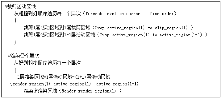
当观察者快速运动,更新全部层次的过程变得过多和漫长。就像在纹理裁剪图(texture clipmaps),我们更新各个层次以从粗糙到好(coarse-to-fine )的顺序,在达到处理预算时停止。我们选择以更新的采样(updated samples)数量超过n2时停止,因为在未更新好的层次的裁剪区域(clip regions)是落后的,它们逐渐地裁剪关联的活动区域,直到它们为空。这样做的后果是接近观察者的快速运动丢失了高精度细节。一个有趣的结果是渲染负荷事实上降低了当观察者运动时。
我们在裁剪区域(clipmap regions)定义下面约束:
1. l+1层裁剪区域属于l层裁剪区域,通过一个分级的距离表示,我们需要裁剪区域嵌套以进行从粗糙到好的地形几何预测。预测需要在各个方面维持一个网格。
2. l+1活动区域属于l层活动区域,渲染数据必须是呈现的在clipmap中的数据的一个子集。
3. l层活动区域的周长必须取决于连续的顶点,以构成一个在比较粗糙的l-1层的密封的边界。
4. l+1层活动区域属于l层活动区域,渲染区域必须至少两个格网单元宽度以允许在两个层次之间两许的渐变。
6. 几何裁剪图渲染(Geometry clipmap rendering)
6.1 基本的渲染算法(Basic rendering algorithm)
给出期望的活动区域,我们通过下面算法渲染地形:
从第5节我们了解到,活动区域被裁剪为裁剪区域,并且比较粗糙的活动区域满足约束条件2-4。注意到,如果一个活动区域为空,则构造完全的活动区域l,l>k同样为空。这相当普遍对于好的层次是空的。活动区域,由于它们的裁剪区域已经在时间内被更新了(如观察者运动得很快),或者由于好的层次是无必要的(如观察者远高于地形表面观察地形)。
既然好的层次是解决观察者的,我们渲染各层从好到粗糙的顺序以利用硬件遮挡消隐。L层渲染区域被分割为4各矩形区域,它们分别通过triangle strips渲染,如图3。最多的strip长度为顶点优化而选择 [Hoppe 1999] ,并且三角形带(triangle strips)分组在一起以实现大批量渲染(batch)。连续的规则格网访存在显存层次中的各层能够很好处理。当前,二维的环形访问(toroidal access)需要CPU反复计算顶点索引每帧,但是,这很快会得到解决在以后。
图3:一个渲染区域的三角带(triangle strip)生成图示(在实际中,三角带达到20个三角形长度)
6.2渐变区域为了可视的连贯性(Transition regions for visual continuity)
上面提及的简单算法描述,由于2的幂(power-of-two mismatch)在边界上的不匹配,存在不同渲染区域之间的裂缝。为了除去裂缝并且提供时间上的连续性。我们让 每层渲染区域外边界附近的几何网格morph 以便于让几何网格过渡到较为粗糙的l-1层。Morph是相对于视点(vx,vy)的地形顶点的空间网格坐标(x,y)的函数。所以这种渐变不是基于时间的,但能代替跟踪连续的观察者位置。
通过实现,我们发现一次渐变的宽度约为10n个网格单元时效果很好,如果w更加小,层次边界会变得明显,如果W比较大,好的细节会存在不必要的丢失。如果好的l+1层活动区域太接近,我们计算w = min(10n, min_width(l)), 容易看出,min_width(l)最少为2 (参见图4)。
想起前面提到的,每个顶点存储为(x, y, z, zc)向量,zc 是下一个l-1粗糙层的高度,我们从下面的公式活动morphed后的高度:
![]() 可以类似计算得到。这里的
可以类似计算得到。这里的![]() 指示在区域L的格网中的视点的连续的坐标,xmin 和xmax 为以整数表示的活动区域L的范围。期望的熟悉是α的估值为0除非渐变区域在边界上直线地倾斜到1。这样的评估大约需要十条GPU顶点程序,看来这会添加渲染负荷。
指示在区域L的格网中的视点的连续的坐标,xmin 和xmax 为以整数表示的活动区域L的范围。期望的熟悉是α的估值为0除非渐变区域在边界上直线地倾斜到1。这样的评估大约需要十条GPU顶点程序,看来这会添加渲染负荷。
T-junction removal. 尽管几何渐变能够避免裂缝,但是边界上的T-junctions仍然由于丢失了象素而存在。为了缝合相邻的层以形成密不透水的网格,我们使用 在渲染边界上渲染o面积三角形 的简单简介方案。
图4:边界外附近的渐变区域,让l层平滑地和比较粗糙的l-1层混合
6.3 Texture mapping
回想起前面提到的每个clipmap层次需要存储纹理用于光栅化(如:normal map)。一个可行的方案是让硬件mip mapping(Multi-Image pyramid mapping多重贴图映射,近距离用简单图像,远距离用细节的图像)控制纹理的LOD。纹理在每一clipmap层将会有它自己的mipmap金字塔。这需要效果33%倍更多的内存。注意到金子塔中比较粗糙的mipmap层次准确地符合在较粗糙clipmap层次中的子区域。所以它们应该能够在在纹理clipmaps中共享 [Tanner et al 1998]。但我们缺少硬件能力,值得注意的是,让硬件来控制mipmap层次是有问题的。如果存储在纹理中的分辨率不是十分高,由于mipmap层次没达到下一个粗糙层次,会在渲染区域边界出现明显的纹理分辨率过渡。这种明显的过渡当观察者在地形表明上向前移动时可以看得出来。
一种代替的计划是,我们设计一个轮流的方案。我们全部禁止mipmapping,并且通过在几何网格上应用同样的空间渐变实现在纹理上进行LOD(细节层次简化)。因此,Thus texture LOD is based on viewer distance rather than on screen-space derivatives as in hardware mipmapping. The main element lost in this approximation is the dependence of texture LOD on surface orientation. When a surface is oriented obliquely, one can no longer access a coarser mipmap level to prevent aliasing. How-ever, graphics hardware commonly supports anisotropic filtering, whereby more samples are combined from the original finest level. Consequently, the absence of mipmaps is not a practical issue for surface orientation dependence.
The spatially based texture LOD scheme is easily implemented in the GPU pixel shader. When rendering level l, we provide the shader with the textures from levels l and l-1, and blend these using the same α parameter already computed in the vertex shader for geometry transitions. Figure 5 shows an example.
| No transitions (gaps) | Blend regions (α) |
| Geometry transitions | Geometry + texture transitions |
Figure 5: Visual continuity achieved with transition morphs (demonstrated with a low-resolution clipmap of size n=127).
6.4 视锥剔除消隐(View-frustum culling)
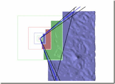
接下来,我们应用视锥剔除。对于裁减图中的每一层,我们保持该地形的zmin, zmax 边界。前面提过,每个渲染区域被分割为四个矩形区域。每个二维矩形的范围由地形边界[zmin,zmax]决定。我们将这个盒与四棱锥型的视锥相交,并将结果映射到XY平面上。沿轴向分布的矩形边界用来裁剪给定的矩形区域,如图6。视锥剔除能够降低1/3的渲染量对于90度的视野来说。
图6:视锥剔除消隐的结果(从上往下观察)
7. Terrain compression
地形高度图Height maps are remarkably coherent in practice, significantly more so than typical color images, and thus offer a huge opportu-nity for compression. To interact efficiently with the geometry clipmap structure, the decompression algorithm must support “region-of-interest” (ROI) queries at any power-of-two resolution.
We have adopted a simple pyramid compression scheme. We first create a terrain pyramid T1..Tm by successively downsam-pling the fine terrain Tm into coarser levels using a linear filter 1l−. Then, each pyramid level T()lT DT =l is predicted from its next coarser level Tl-1 through interpolatory subdivision 1 (Section 5), and the residual 1()lUT−()lllRTUT−=− is compressed using an image coder.1 Since the compression is lossy, Rl is approxi-mated by l. Therefore, we reconstruct the levels in coarse-to-fine order as lTUR1()ll T R − = + 1 () l l l R T UT−= − , and compress the residuals rede-fined as , so that the errors do not accumulate.
Since coarser levels are viewed from afar, our first approach was to give their approximations lT less absolute accuracy. Specifi-cally, we would scale the residuals lR by 2lm− prior to quantization. However, while this is a correct argument for geometric fidelity, we discovered that this results in poor visual fidelity, because both the normal map and z-based coloring then present quantization artifacts (since they are inferred from the decompressed geometry). The solution is to compress all level residuals with the same absolute accuracy.
The quantized residuals are compressed using the PTC image coder of Malvar [2000], which has several nice properties for our purpose. It avoids blocking artifacts by defining overlapping basis functions, yet the bases are spatially localized to permit efficient regional decompression. Also, the coder supports im-ages of arbitrary size (if the encoding fits within 2 GB). Decompression takes place only during the incremental uploads to video memory, and is thus sufficiently fast (Table 1).
We are able to implement the compression preprocess within a 32-bit address space by performing all steps as streaming compu-tations. For the 40GB U.S. data, the complete procedure from original terrain Tm to compressed residuals l takes about 5 hours, much of which is disk I/O. Section 9 reports the rms of the compression error mmTRT−. In our experience, the compressed terrain is visually indistinguishable from the original, except at the sharp color transition associated with the coastline.
As future work, it would be interesting to compare with a com-pression scheme like Normal Meshes [Guskov et al 2000] in which the downsampling filter D is an impulse function.
1 We precompute the optimal filter D (of size 1111) such that U(D(Tl) gives the best L2 approximation of Tl, by solving a linear system on a subset of the given terrain. y Clipmaps (Online ID 0350) Page 6 of 8
8. 地形合成(Terrain synthesis)
几何裁剪图为我们提供了一个自然的结构,通过随机细分或多分辨率纹理合成生成细节。其中存在一个约束:合成过程必须具有空间确定性,这样对于同一区域在一次运行过程中生成的细节总是相同。
我们通过添加无约束的高斯噪音给向上抽样的比较粗糙的地形实现了分形位移。噪声变量在每一层放大以匹配实际的地形。例如,差值(residuals)变量按上一节的方法计算。插入细分所具有的C1 平滑度是避免表面折痕效果的关键。为了更有效评估,我们存储预计算预计算的高斯噪声值在一个表里,并且通过一个顶点坐标上的求模操作进行索引。大小为50的表足够消除任何重复样式或者可辨认的条带(recognizable banding)。
我们希望通过GPU的GPU pixel shader实现合成过程,以便地形几何数据能够完整地在显存当中。尽管一些GPU已经具有必须的“render-to-vertex”能力,但是仍没广泛展露该能力,因此,我们采取CPU计算的方案。尽管这样,运行时计算仍然相当快的。
过程式合成允许我们地形以无限的区域和分辨率生成,并且提供巨大的潜力。在我们的经验看来,简单的分形噪声与可量度的高程数据相比还是不够真实的。但是我们希望更多值得探讨的合成技术能够引入地形景观当中。接下来的挑战就是让这些技术快速、具有空间确定性以及或许能够在GPU上实现。
| 粗糙几何+0细节 | 粗糙几何+分形细节 |
图7:在好的层次进行地形合成的例子。对于11层的几何裁剪图,仅仅最粗糙的三层需要存储几何信息。
9. 结果和讨论(Results and discussion)
We have experimented with two USGS datasets. The smaller one is a 16,3852 grid of the Puget Sound area at 10m spacing, with 16-bit height values at 0.1m vertical resolution. The full-resolution grid is assigned to level l=9, such that it has 652 extent at the coarsest level l=1.
The larger dataset is a 216,00093,600 height map of the conter-minous United States at 30m spacing and 1.0m vertical resolution. (More precisely, spacing is 1 arc-sec in both longitude and lati-tude, with extents [126癢,66癢]x[24癗,50癗].) In a clipmap with m=11 levels, it occupies a 21293 rectangle at the coarsest level. (We render it flat even though it is parametrized by spheri-cal coordinates.)
Figure 8 shows these terrains rendered into a window of size 640480 pixels, with a field-of-view of 90. We used a PC with a 3.0 GHz Pentium4 CPU, 1 GB system memory, and an ATI Radeon 9800XT GPU with 256MB video memory. In addition to shading the terrain with a normal map, we also apply color with a simple 1D texture based on the terrain z coordinate.
| Portion of 16,38516,385 grid of Puget Sound | Portion of 216,00093,600 grid of U.S |
Figure 8: The two datasets rendered using geometry clipmaps.
Rendering rate. For m=11 levels of size 2552, we obtain 120 frames/sec with frustum culling, at a rendering rate of 59 MΔ/sec. (With 4x framebuffer multisampling, it drops to 95 frames/sec.) By comparison, Lindstrom and Pascucci [2002] report 3 MΔ/sec, and Cignoni et al [2003b] achieve 16 MΔ/sec. On present, com-parable hardware (GeForceFX 5800/5900), these authors now obtain rates of 21 MΔ/sec and 65 MΔ/sec respectively.
Update rate. Our threshold processing budget for updating the clipmap is a full n譶 level. Table 1 shows the execution times of the update steps for this worst case. It is likely that these times overlap with GPU processing. During smooth viewer motions, the update times are generally less because only fractions of levels need be updated. In practice, our system maintains a nearly uniform rate of 60 frames/sec. Note that it will soon be possible to perform all steps (except for decompression) using the GPU, thanks to the regular-grid data structure.
| Update step | Time (msec) |
| Computation of zc | 2 |
| Interpolatory subdivision U | 3 |
| Decompression or Synthesis | 8 or 3 |
| Upload to video memory | 2 |
| Normal map computation | 11 |
| Total | 21 or 26 |
Table 1: Times for updating a full n譶 level (n=255).
Draft – Do not distribute. 2004/05/03 9:57:33 AM geomclipmap45.doc SIGGRAPH 2004 Submission Geometry Clipmaps (Online ID 0350) Page 7 of 8
Error analysis. There are two sources of error, compression error and LOD error, and we analyze these separately.
Compression error. The Puget Sound dataset is compressed from 537 MB to 8.5 MB, with an rms error of 1.0m (PSNR=20log10(zmax/rms)=72.6dB). The U.S. dataset is com-pressed from 40.4 GB to 355 MB, with an rms error of 1.8m (PSNR=67.7dB). These rms errors are quite small – only about 10% and 6% of the inter-sample spacing, respectively.
Screen-space LOD error. In Section 4, we estimated the screen-space triangle size s for a given clipmap size n. The analysis relied on the fact that terrain triangles have compact shape if the terrain slope is assumed small. If instead the terrain has steep slope, triangles can become arbitrarily elongated and their screen-space extent is no longer bounded, which is unsatisfactory.
However, the more relevant measure is the screen-space geomet-ric error, i.e. the screen-projected difference between the rendered mesh and the original terrain (Section 2). And, we can analyze this error if provided knowledge of the spectral properties of the terrain geometry.
For each terrain level Tl, we are interested in the error function llm where PL denotes the piecewise linear mesh interpolant over the (x,y) domain. This function is related to the (continuous) spectral density of the terrain signal. Since the grid spacing g()() e PLT PLT = −l in level l projects to s pixels in screen space, the screen-space projection of error at location (x,y) is at most (,)lexy
(,)ˆ(,)lllexyexysg=.
(The error is smaller if the view direction is not horizontal.) Thus, given a terrain dataset, we compute norms of l to estimate the screen-space error for each rendered level, as shown in Table 2. ˆe e
The results reveal that the rms screen-space error is smaller than one pixel. This is not unexpected, since the triangle size s is only 3 pixels and the difference between those planar triangles and the finer detail is generally smaller yet. We find the larger l error values to be misleading, because the acquired terrain data contains mosaic misregistration artifacts that create artificial cliffs, and it only takes one erroneous height value to skew the statistic. Instead, we prefer to examine the 99.9ˆmax()th percentile error, and we see that it too is still smaller than a pixel. (See also the accompanying video.)
In comparison, Cignoni et al [2003b] use the same window size and a tolerance of 3 pixels. Lindstrom and Pascucci [2002] also use a 640x480 window, and mention that geomorphs allow the tolerance to reach 6 pixels without noticeable visual artifacts. The authors of both these papers report that on present hardware their schemes can now maintain a screen-space tolerance of 1 pixel.
The error analysis suggests that we could afford to reduce the clipmap size while still maintaining acceptable geometric fidelity. However, the true limiting factor is visual fidelity, which in turn strongly depends on surface shading — this is the basic premise of normal mapping. Therefore, even if we used coarser geometry, we would still have to maintain high-resolution normal maps. In our system, these normal maps are generated from the geometry clipmap itself. Indeed, the compressed mipmap pyramid can be seen as an effective scheme for encoding the normal map, with a secondary benefit of providing carrier geometry.
The non-uniformity of screen-space error le across levels could be exploited by adapting the sizes of individual clipmap levels. For instance, smooth hills would require a sparser tessellation (in screen space) on the nearby smooth terrain than on the farther hill silhouettes. As just discussed, one would have to verify that the surface shading is not adversely affected. Both the Puget Sound and U.S. terrain datasets appear to have rather uniform spectral densities. In the U.S. data, the error begins to diminish at coarse levels, reflecting the fact that the Earth is smooth at coarse scale. ˆ
ˆ rms( ) l e ˆ max( ) l e ˆ max( ) l e
| Levell | Puget Sound | U.S. | |||||||
| .999ˆ()lPe | ˆrms()le | .999ˆ()lPe | |||||||
| 1 | 0.12 | 0.58 | 1.27 | 0.02 | 0.12 | 0.30 | |||
| 2 | 0.14 | 0.75 | 1.39 | 0.04 | 0.20 | 0.43 | |||
| 3 | 0.15 | 0.86 | 2.08 | 0.06 | 0.32 | 0.62 | |||
| 4 | 0.15 | 0.93 | 2.50 | 0.09 | 0.51 | 0.96 | |||
| 5 | 0.14 | 0.96 | 3.38 | 0.12 | 0.68 | 1.37 | |||
| 6 | 0.13 | 0.94 | 5.55 | 0.13 | 0.78 | 2.03 | |||
| 7 | 0.11 | 0.83 | 8.03 | 0.14 | 0.84 | 2.59 | |||
| 8 | 0.11 | 0.75 | 14.25 | 0.13 | 0.86 | 4.16 | |||
| 9 | 0.00 | 0.00 | 0.00 | 0.12 | 0.90 | 8.18 | |||
| 10 | 0.11 | 0.90 | 11.70 | ||||||
| 11 | 0.00 | 0.00 | 0.00 | ||||||
表2: Analysis of screen-space geometric error, in pixels. Columns show rms, 99.9th percentile, and maximum errors. (n=255, W=640, ϕ=90, i.e. s=3).
Space requirement. For the U.S. dataset, the number of levels is m=11, and the compressed terrain occupies 355 MB in system memory. For our default clipmap size n=255, the geometry clipmap needs 16mn2=11 MB in video memory for the vertex geometry. (Since we cannot yet do level prediction on the GPU, we also replicate the z height data in system memory, requiring 4mn2=3 MB.) The normal maps have twice the resolution, but only 2 bytes/sample, so need an additional 8mn2=6 MB. Thus, overall memory use is about 375 MB, or only 0.02 bytes/sample. As shown in Table 3, our space requirement is significantly less than in previously reported results. Since the data fits within the memory of a standard PC, we avoid runtime disk accesses.
| LOD scheme | Grid size | Num. of samples | Runtimespace | Bytes/sample |
| Hoppe [1998] | 4K2K | 8M | 50 MB | 6.0 |
| Lindstrom [2002] | 16K16K | 256M | 5.0 GB | 19.5 |
| Cignoni et al [2003a] | 8K8K | 64M | 115 MB | 1.8 |
| Cignoni et al [2003b] | 6133132 | 1G | 4.5 GB | 4.5 |
| Geometry clipmaps | 16K16K | 256M | 25 MB | 0.10 |
| 216K94K | 20G | 375 MB | 0.02 |
Table 3: Comparison of runtime space requirements. Prior methods also require storage of a normal map for surface shad-ing (which is not included here), whereas ours is computed on-the-fly from the decompressed geometry.
Precision. For m=11 levels, floating-point precision is not yet an issue. To allow an arbitrary number of levels, a simple solution is to transform the viewpoint and view matrix into the local coordi-nate system of each clipmap level (using double precision as in [Cignoni et al 2003b]).
Networked viewer. The compressed terrain pyramid residuals l could be stored on a server and streamed incrementally (based on user motion) to a lightweight client. The necessary bandwidth is small since the compression factor is on the order of 60-100. R
Draft – Do not distribute. 2004/05/03 9:57:33 AM geomclipmap45.doc SIGGRAPH 2004 Submission Geometry Clipmaps (Online ID 0350) Page 8 of 8
10. Summary and future work
A pre-filtered mipmap pyramid is a natural representation for terrain data. We present geometry clipmaps, which cache nested rectangular extents of this pyramid to create view-dependent approximations. A unique aspect of the framework is that LOD is independent of the data content. Therefore the terrain data does not require any precomputation of refinement criteria. Together with the simple grid structure, this allows the terrain to be created lazily on-the-fly, or stored in a highly compressed format. Nei-ther of these capabilities has previously been available.
We demonstrate interactive flight over a 20-billion sample grid of the U.S., stored in just 355 MB of memory and incrementally decompressed at 60 frames/sec. The decompressed data has an rms error of 1.8 meters over the U.S. The view-dependent LOD has a screen-space error whose 99.9th percentile is smaller than one pixel, and the rendering is temporally smooth.
The representation of geometry using regular grids should become even more attractive as vertex and image buffers become unified. This unification will enable the highly parallel GPU rasterizer to process geometry in addition to images. An earlier solution will be to use vertex textures (e.g. as in DirectX9 Vertex Shader 3.0) to toroidally access geometry images [Gu et al 2002], thereby greatly simplifying implementation of geometry clipmaps.
Geometry clipmaps unify the LOD management of the terrain geometry and its associated texture signals. The spatially based LOD structure lets low-resolution textures be applied without visual discontinuities at level boundaries. Beyond our runtime creation of normal maps, we envision that non-local functions such as shadow maps can be similarly computed in a lazy fashion.
Geometry clipmaps present many more avenues for future work:
• Improved terrain synthesis, e.g. using machine learning.
• Geometry synthesis on the GPU, e.g. [Losasso et al 2003].
• Procedural terrain overlays.
• Runtime terrain modification.
• Terrain collision detection within the GPU.
• GPU-based decompression of geometry images.
• Extension to a spherical domain, e.g. [Cignoni et al 2003b].
Acknowledgments
We thank Rico Malvar and Erin Renshaw for the PTC image compression library, the Flight Simulator Group for obtaining the U.S. elevation data, and Peter Lindstrom for preparing the Puget Sound dataset. Thanks also to Cignoni, Gobbetti, and Lindstrom for testing their terrain LOD schemes on comparable hardware.
References
BISHOP, L., EBERLY, D., WHITTED, T., FINCH, M., AND SHANTZ, M. 1998. Designing a PC game engine. IEEE CG&A 18(1), 46-53.
BLOW, J. 2000. Terrain rendering at high levels of detail. Proc. 2000 Game Developers Conference.
CIGNONI, P., PUPPO, E., AND SCOPIGNO, R. 1997. Representation and visualization of terrain surfaces at variable resolution. The Visual Computer 13(5), 199-217.
CIGNONI, P., GANOVELLI, F., GOBBETTI, E., MARTON, F., PONCHIO, F., AND SCOPIGNO, R. 2003a. BDAM – Batched dynamic adaptive meshes for high performance terrain visualization. Computer Graph-ics Forum 22(3).
CIGNONI, P., GANOVELLI, F., GOBBETTI, E., MARTON, F., PONCHIO, F., AND SCOPIGNO, R. 2003b. Planet-sized batched dynamic adaptive meshes (P-BDAM). IEEE Visualization 2003.
COHEN-OR, D., AND LEVANONI, Y. 1996. Temporal continuity of levels of detail in Delaunay triangulated terrain. IEEE Visualization. 37-42.
DE FLORIANI, L, MAGILLO, P. AND PUPPO, E. 1997. Building and travers-ing a surface at variable resolution. IEEE Visualization 1997, 103-110.
DOGGETT, M, AND HIRCHE, J. 2000. Adaptive view-dependent tessella-tion of displacement maps. Graphics Hardware Workshop, 59-66.
DÖLLNER, J., BAUMANN, K., AND HINRICHS, K. 2000. Texturing tech-niques for terrain visualization. IEEE Visualization 2000, 227-234.
DYN, N., GREGORY, J., AND LEVIN, D. 1987. A 4-point interpolatory subdivision scheme for curve design, CAGD 4, 257-268.
DUCHAINEAU, M., WOLINSKY, M., SIGETI, D., MILLER, M., ALDRICH, C., AND MINEEV-WEINSTEIN, M. 1997. ROAMing terrain: Real-time op-timally adapting meshes. IEEE Visualization 1997, 81-88.
EL-SANA, J., AND VARSHNEY, A. 1999. Generalized view-dependent simplification. Proceedings of Eurographics 1999, 83-94.
FOURNIER, A., FUSSELL, D., AND CARPENTER, L. 1982. Computer rendering of stochastic models. Comm. of the ACM 25(6), 371-384.
GU, X., GORTLER, S., AND HOPPE, H. Geometry images. ACM SIG-GRAPH 2002, 355-361.
GUSKOV, I., VIDIMČE, K., SWELDENS, W., AND SCHRÖDER, P. Normal meshes. SIGGRAPH 2000, 95-102.
GUMHOLD, S., AND HÜTTNER, T. 1999. Multiresolution rendering with displacement mapping. Graphics Hardware Workshop 1999.
HITCHNER, L., AND MCGREEVY, M. 1993. Methods for user-based reduction of model complexity for Virtual Planetary Exploration. Proc. SPIE 1913, 622-636.
HOPPE, H. 1998. Smooth view-dependent level-of-detail control and its application to terrain rendering. IEEE Visualization 1998, 35-42.
HOPPE, H. 1999. Optimization of mesh locality for transparent vertex caching. ACM SIGGRAPH 1999, 269-276.
KOBBELT, L. 1996. Interpolatory subdivision on open quadrilateral nets with arbitrary topology. Eurographics 1996, 409-420.
LEVENBERG, J. 2002. Fast view-dependent level-of-detail rendering using cached geometry. IEEE Visualization 2002, 259-266.
LEWIS, J. 1987. Generalized stochastic subdivision. ACM Transactions on Graphics 6(3), 167-190.
LINDSTROM, P., KOLLER, D., RIBARSKY, W., HODGES, L., FAUST, N., AND TURNER, G. 1996. Real-time, continuous level of detail rendering of height fields. ACM SIGGRAPH 1996, 109-118.
LINDSTROM, P., AND PASCUCCI, V. 2002. Terrain simplification simpli-fied: A general framework for view-dependent out-of-core visualization. IEEE TVCG 8(3), 239-254.
LOSASSO, F., HOPPE, H, SCHAEFER, S., AND WARREN, J. 2003. Smooth geometry images. Symposium on Geometry Processing 2003, 138-145.
MALVAR, H. 2000. Fast Progressive Image Coding without Wavelets. Data Compression Conference (DCC '00), 243-252.
MILLER, G. 1986. The definition and rendering of terrain maps. ACM SIGGRAPH 1986, 39-48.
MOULE, K., AND MCCOOL, M. 2002. Efficient bounded adaptive tessella-tion of displacement maps. Graphics Interface 2002.
PAJAROLA, R. 1998. Large scale terrain visualization using the restricted quadtree triangulation. IEEE Visualization 1998, 19-26.
RABINOVICH, B., AND GOTSMAN, C. 1997. Visualization of large terrains in resource-limited computing environments. IEEE Visualization.
RÖTTGER, S., HEIDRICH, W., SLUSALLEK, P., AND SEIDEL, H.-P. 1998. Real-time generation of continuous levels of detail for height fields. Central Europe Conf. on Computer Graphics and Vis., 315-322.
TANNER, C., MIGDAL, C., AND JONES, M. 1998. The clipmap: A virtual mipmap. ACM SIGGRAPH 1998, 151-158.
VLACHOS, A., PETERS, J., BOYD, C., AND MITCHELL, J. 2001. Curved PN triangles. Symposium on Interactive 3D Graphics, 159-166.
WEI, L, AND LEVOY, M. Fast texture synthesis using tree-structured vector quantization. ACM SIGGRAPH 2000, 479-488.
WAGNER, D. 2004. Terrain geomorphing in the vertex shader. In ShaderX2: Shader Programming Tips & Tricks with DirectX 9. Wordware Publishing.
WILLIAMS, L. 1983. Pyramidal parametrics. ACM SIGGRAPH. 1-11.
Draft – Do not distribute. 2004/05/03 9:57:33 AM geomclipmap45.doc


