D3D10与Geometry Shader用于细分曲面几点学习笔记(1)
D3D10与Geometry Shader用于细分曲面几点学习笔记(1)
华南理工大学,张嘉华 newzjh@126.com QQ:188318005,欢迎和我多多交流,共同学习进步
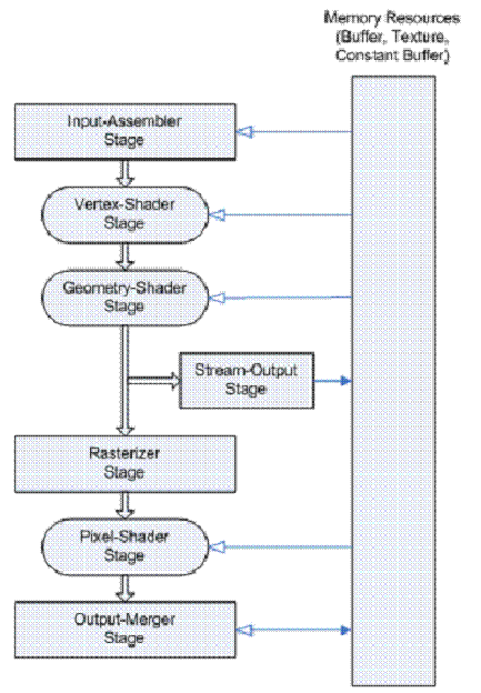
1. Direct3D 10的流水线
在细分曲面里面,最有新用途的就是Geometry Shader和Stream Out,前者可以输入一些数据,然后产生一些三角形,后者可以断绝Pixel Shader,做完Geometry Shader就直接输出回Input Assembler,这就意味着可以做GPU递归和迭代。
2、Direct3D 10环境配置
首先当然就是Vista 和NV8800+啦,接着就是基本环境的搭建.有能力的话可以考虑一下搭建一个自己的引擎.
有一个朋友问到我如何实现内嵌消息循环实现设备窗口大小改变.通常情况下我们都需要在窗口初始化的时候定义消息循环,然后把创建好的窗口的Hwnd传递给引擎图形设备的创建函数,然后订阅这个消息循环的WM_SIZE消息,在窗口改变的时候由应用程序调用引擎改变设备大小.那么能否像Dotnet那样通过添加一个订阅句柄到消息循环中呢.其实是可以的.首先通过GetWindowLongPtr第二个参数设置GWL_WNDPROC获得我们应用程序的消息循环函数指针,因为对于引擎来说,通常是dll,它不可能知道外部应用程序那个函数实现了消息循环,而我们创建引擎的时候也只传递进hwnd,因此需要用GetWindowLongPtr获得外部的消息循环函数,然后用引擎内部的消息循环函数替代,代码2.1实现了这个目的.那么另外一个问题是如何只添加我们需要的消息订阅绑定而不覆盖掉,我们需要对引擎的消息循环函数在默认情况下,即不触发我们引擎消息的情况下调用回外部应用程序的消息循环函数.
----------------------------------------------------------------------------------------------------------------------------------------
g_applicationwindproc= (WNDPROC)(::GetWindowLongPtr(hwnd, GWL_WNDPROC));
SetWindowLongPtr(hwnd,GWL_WNDPROC,(LONG_PTR)&GComponentModel::ComponentModelMsgProc);
----------------------------------------------------------------------------------------------------------------------------------------
代码2.1:用引擎的消息循环函数代替外部的消息循环函数
代码2.2在默认的情况下最后调用了外部的消息循环函数applicationwindproc.
----------------------------------------------------------------------------------------------------------------------------------------
LRESULT GComponentModel::ComponentModelMsgProc( HWND hWnd, UINT msg, WPARAM wParam, LPARAM lParam )
{
switch( msg )
{
case WM_CLOSE:
GComponentModel::Closing();
return 0;
case WM_SIZE:
RECT rect1;
RECT rect2;
if (GGraphicsDevice::GetHandle())
{
GetWindowRect(GGraphicsDevice::GetHandle(),&rect1);
GetClientRect(GGraphicsDevice::GetHandle(),&rect2);
if (rect1.right-rect1.left==0 || rect1.bottom-rect1.top==0||
rect2.right-rect2.left==0 || rect2.bottom-rect2.top==0)
{
GComponentModel::SetFocus(false);
}
else
{
GComponentModel::SetFocus(true);
GGraphicsController::SwitchAccordingWindow();
}
}
return 0;
default:
return g_applicationwindproc(hWnd, msg, wParam, lParam );
}
}
----------------------------------------------------------------------------------------------------------------------------------------
代码2.2:引擎内部的消息循环函数
有了这些之后,DirectX10完全放弃了固定流水线,全部用可编程流水线,所以也就是必须进行GPU Coding,写HLSL等,并且对于输入更研究,创建IA的时候需要HLSL的输入与定义一致。
下面是Direct3D10 C++的一个IA定义与设置:
----------------------------------------------------------------------------------------------------------------------------------------
ID3D10InputLayout* pVertexLayout ;
D3D10_INPUT_ELEMENT_DESC layout[] =
{
{ "TEXTURE0", 0, DXGI_FORMAT_R32G32_FLOAT, 0, 0, D3D10_INPUT_PER_VERTEX_DATA, 0 },
};
UINT numElements = sizeof(layout)/sizeof(layout[0]);
// Create the input layout
D3D10_PASS_DESC PassDesc;
m_hTechs[m_PostEffectType]->GetPassByIndex( 0 )->GetDesc( &PassDesc );
hr = pd3dDevice->CreateInputLayout( layout, numElements, PassDesc.pIAInputSignature, PassDesc.IAInputSignatureSize, &pVertexLayout );
if( FAILED( hr ) )
return hr;
// Set the input layout
pd3dDevice->IASetInputLayout( pVertexLayout );
----------------------------------------------------------------------------------------------------------------------------------------
代码2.1:Direct3D10 C++的一个IA定义与设置
描述了顶点程序输入的每个数据只有一个元素,纹理坐标0,格式是R32G32浮点形,放置在第一个流第一索引作为顶点数据,接着与Fx文件的Pass联结,我们可以看到CreateInputLayout输入既有元素描述也有Fx的Pass的输入描述,两者必须严格相符才能成果调用,这与Direct3D9里面的FVF和CreateVertexDeclaration有很大区别.
Direct3D10里面还有一个就是可以对显存Buffer实时解析用途,也就是说某个缓冲它不再固定是顶点缓冲还是纹理,而是在输入和输出的时候通过一个View去描述它.
3、UI的实现
在Direct3D9,我们可以简单地使用固定流水线的DrawPrimitiveUP函数去绘制一个个UI对象,代码3.1是我的引擎里面在D3D9时绘制UI的一个函数,用颜色去填充一个区域,顶点为Transformed类型的xyz,当然你也可以用Sprite去实现.
----------------------------------------------------------------------------------------------------------------------------------------
HRESULT G2DGraphics::FillBox(float x1,float y1,float x2,float y2,DWORD color1,DWORD color2,DWORD color3,DWORD color4)
{
HRESULT hr=S_OK;
//透明则略过
if ((color1>>24 & color2>>24 & color3>>24 & color4>>24)==0)
return S_OK;
TCVertex Vertices[4];
Vertices[0].x=x1;
Vertices[0].y=y1;
Vertices[0].z=0;
Vertices[0].rhw=1;
Vertices[0].color=color1;
Vertices[1].x=x2+1;
Vertices[1].y=y1;
Vertices[1].z=0;
Vertices[1].rhw=1;
Vertices[1].color=color2;
Vertices[2].x=x1;
Vertices[2].y=y2+1;
Vertices[2].z=0;
Vertices[2].rhw=1;
Vertices[2].color=color3;
Vertices[3].x=x2+1;
Vertices[3].y=y2+1;
Vertices[3].z=0;
Vertices[3].rhw=1;
Vertices[3].color=color4;
IDirect3DDevice9* pd3dDevice=GGraphicsDevice::GetDevice();
//IDirect3DVertexDeclaration9 *pDecl = NULL;
//pd3dDevice->GetVertexDeclaration( &pDecl ); // Preserve the sprite's current vertex decl
hr=pd3dDevice->SetFVF( D3DFVF_TCVertex );
hr=pStateBlock->Apply();
hr=pd3dDevice->SetRenderState( D3DRS_ALPHABLENDENABLE, !(color1>>24==255 && color2>>24==255 && color3>>24==255 && color4>>24==255) );
hr=pd3dDevice->SetTexture(0,NULL);
hr=pd3dDevice->SetVertexShader( NULL );
hr=pd3dDevice->SetPixelShader( NULL );
hr=pd3dDevice->DrawPrimitiveUP(D3DPT_TRIANGLESTRIP ,2, Vertices,sizeof(TCVertex));
hr=pd3dDevice->SetRenderState(D3DRS_ALPHABLENDENABLE,FALSE);
hr=pd3dDevice->SetTextureStageState( 0, D3DTSS_COLOROP, D3DTOP_MODULATE );
hr=pd3dDevice->SetTextureStageState( 0, D3DTSS_ALPHAOP, D3DTOP_MODULATE );
//pd3dDevice->SetVertexDeclaration( pDecl );
//pDecl->Release();
return S_OK;
}
代码3.1:用绘制投影三角形的方式绘制UI
在Direct3D10中再没有了固定流水线的绘制函数,那么很自然的一种想法就是转换为Shader去实现,但是每绘制一个图元,就需要修改一次顶点缓冲,需要锁定,即使使用Dynamic的缓冲在大量图元的情况下也很慢.因此我用了另外一种办法,就是每绘制一个图元修改一次Shader的变量,用固定的顶点去索引Shader变量,在Vertex Shader中再得到具体的顶点屏幕投影值.具体实现时首先为所有UI图形绘制分配一个固定的顶点缓冲,如代码3.2,创建了一个缓冲区只包含四个顶点,每个顶点只保护一个UINT类型的数据,绑定为顶点缓冲.这个UINT元素描述顶点是第几个顶点.
----------------------------------------------------------------------------------------------------------------------------------------
// Create vertex buffer
UINT vertices[] ={0,1,2,3};
D3D10_BUFFER_DESC bd;
bd.Usage = D3D10_USAGE_DEFAULT;
bd.ByteWidth = sizeof( UINT ) * 4;
bd.BindFlags = D3D10_BIND_VERTEX_BUFFER;
bd.CPUAccessFlags = 0;
bd.MiscFlags = 0;
D3D10_SUBRESOURCE_DATA InitData;
InitData.pSysMem = vertices;
hr = pd3dDevice->CreateBuffer( &bd, &InitData, &g_pVertexBuffer );
if( FAILED( hr ) )
return hr;
----------------------------------------------------------------------------------------------------------------------------------------
代码3.2:描述顶点序号的顶点缓冲的创建
接着在具体绘制每个UI图元的时候,如代码3.3计算好每个顶点的位置,通过SetFloatVectorArray,把顶点的坐标和位置赋予GPU,
----------------------------------------------------------------------------------------------------------------------------------------
HRESULT G2DGraphics::FillBox(float x1,float y1,float x2,float y2,DWORD color1,DWORD color2,DWORD color3,DWORD color4)
{
HRESULT hr=S_OK;
ID3D10Device* pd3dDevice=GGraphicsDevice::GetDevice();
//透明则略过
if ((color1>>24 & color2>>24 & color3>>24 & color4>>24)==0)
return S_OK;
int fdevvicewidth=(float)(GGraphicsDevice::GetDeviceWidth());
int fdeviceheight=(float)(GGraphicsDevice::GetDeviceHeight());
float4 positions[4];
float4 colors[4];
float4 uvs[4];
positions[0].x=((float)(x1)/fdevvicewidth-0.5f)*2.0f;
positions[0].y=((float)(y1)/fdeviceheight-0.5f)*-2.0f;
positions[0].z=0;
positions[0].w=1;
colors[0]=ConvertColorFromDwordToFloat4(color1);
uvs[0]=float4(-1.0f,-1.0f,1.0f,1.0f);
positions[1].x=((float)(x2)/fdevvicewidth-0.5f)*2.0f;
positions[1].y=((float)(y1)/fdeviceheight-0.5f)*-2.0f;
positions[1].z=0;
positions[1].w=1;
uvs[1]=float4(-1.0f,-1.0f,1.0f,1.0f);
colors[1]=ConvertColorFromDwordToFloat4(color2);
positions[2].x=((float)(x1)/fdevvicewidth-0.5f)*2.0f;
positions[2].y=((float)(y2)/fdeviceheight-0.5f)*-2.0f;
positions[2].z=0;
positions[2].w=1;
uvs[2]=float4(-1.0f,-1.0f,1.0f,1.0f);
colors[2]=ConvertColorFromDwordToFloat4(color3);
positions[3].x=((float)(x2)/fdevvicewidth-0.5f)*2.0f;
positions[3].y=((float)(y2)/fdeviceheight-0.5f)*-2.0f;
positions[3].z=0;
positions[3].w=1;
uvs[3]=float4(-1.0f,-1.0f,1.0f,1.0f);
colors[3]=ConvertColorFromDwordToFloat4(color4);
g_VertexPositions->SetFloatVectorArray((float*)&positions,0,4);
g_VertexColors->SetFloatVectorArray((float*)&colors,0,4);
g_VertexUvs->SetFloatVectorArray((float*)&uvs,0,4);
// Set the input layout
pd3dDevice->IASetInputLayout( g_pVertexLayout );
// Set vertex buffer
UINT stride = sizeof( UINT );
UINT offset = 0;
pd3dDevice->IASetVertexBuffers( 0, 1, &g_pVertexBuffer, &stride, &offset );
pd3dDevice->IASetPrimitiveTopology( D3D10_PRIMITIVE_TOPOLOGY_TRIANGLESTRIP );
D3D10_TECHNIQUE_DESC techDesc;
g_pUIFillTech->GetDesc( &techDesc );
for( UINT p = 0; p < techDesc.Passes; ++p )
{
g_pUIFillTech->GetPassByIndex( p )->Apply(0);
pd3dDevice->Draw( 4, 0 );
}
return S_OK;
}
----------------------------------------------------------------------------------------------------------------------------------------
代码3.3 用Effect绘制每个UI图元
接着看看代码3.4如何用HLSL实现,和过往Shader不一样的是,HLSL10里由于中间穿插了Geometry Shader,所以Vertex Shader输出顶点位置的语言改变为SV_POSITION,Pixel Shader输出语义改为SV_Target,我们在Vertex Shader对上面输入的只有一个UINT顶点表示顶点序号,索引Effect的变量,得到具体的投影位置等.
----------------------------------------------------------------------------------------------------------------------------------------
uniform float4 pos[8];
uniform float4 color[8];
uniform float4 uv[8];
struct PS_INPUT
{
float4 Pos : SV_POSITION;
float4 color: Color0;
float2 uv : TEXCOORD0;
};
PS_INPUT VS(int i : TEXCOORD0)
{
PS_INPUT Output;
Output.Pos = pos[i];
Output.color=color[i];
Output.uv = uv[i].xy;
return Output;
}
float4 PS_Fill(PS_INPUT input) : SV_Target
{
return input.color;
}
technique10 UIFill
{
pass P0
{
SetVertexShader( CompileShader( vs_4_0, VS() ) );
SetGeometryShader( NULL );
SetPixelShader( CompileShader( ps_4_0, PS_Fill() ) );
SetBlendState( AdditiveBlending, float4( 0.0f, 0.0f, 0.0f, 0.0f ), 0xFFFFFFFF );
SetDepthStencilState( DisableDepth, 0 );
}
}
----------------------------------------------------------------------------------------------------------------------------------------
代码3.4 UI绘制的HLSL实现
4、Geometry Shader
//--------------------------------------------------------------------------------------
// Geometry Shader
//--------------------------------------------------------------------------------------
[maxvertexcount(12)]
void GS( triangle GSPS_INPUT input[3], inout TriangleStream<GSPS_INPUT> TriStream )
{
GSPS_INPUT output;
//
// Calculate the face normal
//
float3 faceEdgeA = input[1].Pos - input[0].Pos;
float3 faceEdgeB = input[2].Pos - input[0].Pos;
float3 faceNormal = normalize( cross(faceEdgeA, faceEdgeB) );
float3 ExplodeAmt = faceNormal*Explode;
//
// Calculate the face center
//
float3 centerPos = (input[0].Pos.xyz + input[1].Pos.xyz + input[2].Pos.xyz)/3.0;
float2 centerTex = (input[0].Tex + input[1].Tex + input[2].Tex)/3.0;
centerPos += faceNormal*Explode;
//
// Output the pyramid
//
for( int i=0; i<3; i++ )
{
output.Pos = input[i].Pos + float4(ExplodeAmt,0);
output.Pos = mul( output.Pos, View );
output.Pos = mul( output.Pos, Projection );
output.Norm = input[i].Norm;
output.Tex = input[i].Tex;
TriStream.Append( output );
int iNext = (i+1)%3;
output.Pos = input[iNext].Pos + float4(ExplodeAmt,0);
output.Pos = mul( output.Pos, View );
output.Pos = mul( output.Pos, Projection );
output.Norm = input[iNext].Norm;
output.Tex = input[iNext].Tex;
TriStream.Append( output );
output.Pos = float4(centerPos,1) + float4(ExplodeAmt,0);
output.Pos = mul( output.Pos, View );
output.Pos = mul( output.Pos, Projection );
output.Norm = faceNormal;
output.Tex = centerTex;
TriStream.Append( output );
TriStream.RestartStrip();
}
for( int i=2; i>=0; i-- )
{
output.Pos = input[i].Pos + float4(ExplodeAmt,0);
output.Pos = mul( output.Pos, View );
output.Pos = mul( output.Pos, Projection );
output.Norm = -input[i].Norm;
output.Tex = input[i].Tex;
TriStream.Append( output );
}
TriStream.RestartStrip();
}
我们先来看看Geometry Shader跟以往的Pixel Shader有什么不同,Geometry Shader不再是以前单独输入的零散的一个个顶点,Geometry Shader的输入相当灵活,可以是一个个顶点也可以是一些些数据,那么在我们这个例子里,输入的是triangle GSPS_INPUT input[3],表示输入数据以三角形组织,输入三个顶点,在Direct3D里面可以输入包括邻接关系的三角形等,这在细分曲面应用中相当重要,我们来看看这个例子,输入和输出都作为函数GS的参数,inout表示这个参数是用于输出的,是一个名为TriStream 的TriangleStream<GSPS_INPUT> 。在这个函数里,通过输入的三个顶点计算了面的法向量和面的中心点,然后输出一个金子塔,每个顶点在for循环里面通过Append语句输出,至于输出的是Triangle Strip还是Triangle List那么要看RestartStrip()的时机,默认是输出Triangle Strip,如果想输出Triangle List必须每输出三个顶点调用一次RestartStrip(),在Geometry Shader 输出如果Stream Out回IA再次使用的数据是难以索引的,所以建议有必须Triangle List用不了Triangle Strip的地方即使顶点重复,还是不要指望索引好。Direct3D10里面多了个DrawAuto的函数,对于Geometry Shader和细分曲面进行迭代是很需要的。
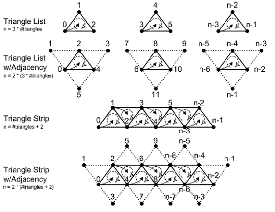
Geometry Shader的输入形式在Direct3D里面有下面几种,
其中能支持邻接关系的有第二和第四种,但是我们不难发现,虽然可以输入邻接三角形,但是只能输入每条边邻接的三角形,对于细分曲面里面三角形的每个顶点的其它邻接三角形信息是无法获得的,那么我们恐怕需要把输入的整个网格以缓冲整个输入。
5、与相关工作对比,细分曲面的一些思考
Realtime Loop subdivision on the GPU[Minho Kim2005],
A Realtime GPU Subdivision Kernel [Shiue等2005]
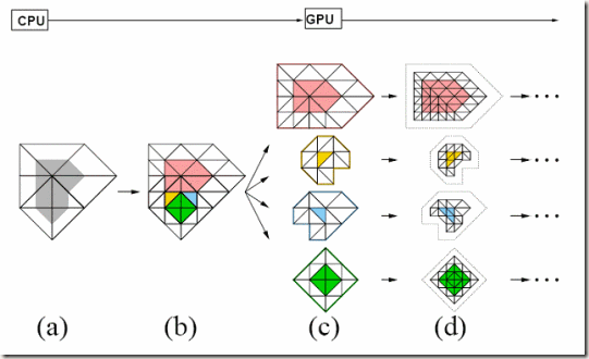
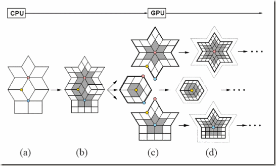
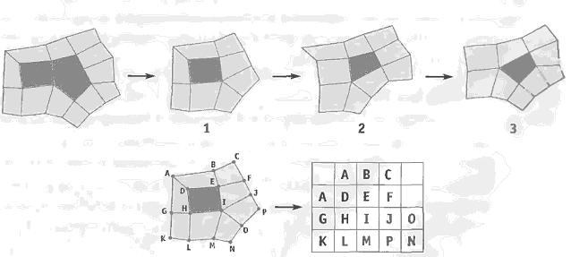
首先想到的是,能否不用切割为一个个Fragment Mesh而直接采用GPU Gems2第7章类似的面片化方法,准确来说应该是三角形为中心的Fragment Mesh形式
对于这种面片化方法我还看不懂一处,就是最后的I右侧如何决定是J还是O
有鉴于此,考虑到Geometry Shader多以三角形为单位,因此容易想到用上面的这种面片化方法,在GPU Gems2第七章里面还提到自适应细分,而因为有了Geometry Shader和Stream Out,所以我们可以做GPU迭代和递归,因此可以面片化为这样的一个个以三角形为中心的Fragment Mesh,然后送进Geometry Shader根据一定阈值分别细分,GPU GEMS2第7章里面还提到消除裂缝和进行Displacement Mapping的方法。
我们先来看看suite 2005的一段Shader
----------------------------------------------------------------------------------------------------------------------------------------
void main ( void ) { / / Co l l e c t t h e look up t a b l e e n t r y
vec4 rgba1 =
t extur e2D ( LookUp , vec2 ( LookupTC . s , 0 . 0 / 3 . 0 ) )
IDX2TC ;
vec4 rgba2 =
t extur e2D ( LookUp , vec2 ( LookupTC . s , 1 . 0 / 3 . 0 ) )
IDX2TC ;
vec4 rgba3 = t extur e2D ( LookUp , vec2 ( LookupTC . s , 2 . 0 / 3 . 0 ) ) ;
i n t t y p e = i n t ( rgba3 . g ) ;
rgba3 = rgba3
IDX2TC ;
/ / Co l l e c t t h e s t e n c i l nodes i n t h e i n p u t p a t c h−t e x t u r e
/ / as i n Fi g u r e s 6 and 7 .
vec4 S [ 9 ] ;
S [ 0 ] = texture2D ( InputPatch , vec2 ( rgba1 . r , 0 ) ) ;
S [ 1 ] = texture2D ( InputPatch , vec2 ( rgba1 . g , 0 ) ) ;
S [ 2 ] = texture2D ( InputPatch , vec2 ( rgba1 . b , 0 ) ) ;
S [ 3 ] = texture2D ( InputPatch , vec2 ( rgba1 . a , 0 ) ) ;
S [ 4 ] = texture2D ( InputPatch , vec2 ( rgba2 . r , 0 ) ) ;
S [ 5 ] = texture2D ( InputPatch , vec2 ( rgba2 . g , 0 ) ) ;
S [ 6 ] = texture2D ( InputPatch , vec2 ( rgba2 . b , 0 ) ) ;
S [ 7 ] = texture2D ( InputPatch , vec2 ( rgba2 . a , 0 ) ) ;
S [ 8 ] = texture2D ( InputPatch , vec2 ( rgba3 . r , 0 ) ) ;
/ / Compute t h e p o s i t i o n u s i n g t h e v e r t e x−s t e n c i l
vec4 vertPos = S [ 0 ]
9 . 0 / 1 6 . 0 +
( ( S [ 1 ]+ S [ 2 ] ) + ( S [ 3 ]+ S [ 4 ] ) )
3 . 0 / 3 2 . 0 +
( ( S [ 5 ]+ S [ 7 ] ) + ( S [ 8 ]+ S [ 6 ] ) ) / 6 4 . 0 ;
/ / Compute t h e p o s i t i o n u s i n g t h e edge−s t e n c i l
vec4 edgePos = ( S [ 0 ]+ S [ 1 ] )
3 . 0 / 8 . 0 +
( ( S [ 2 ]+ S [ 4 ] ) + ( S [ 3 ]+ S [ 5 ] ) ) / 1 6 . 0 ;
/ / Compute t h e p o s i t i o n u s i n g t h e f a c e−s t e n c i l
vec4 facePos = ( ( S [ 0 ]+ S [ 2 ] ) + ( S [ 1 ]+ S [ 3 ] ) ) / 4 . 0 ;
/ / As s i g n t h e v a l i d p o s i t i o n by n ume r i c a l masking
glFragColor = v e r t P o s
f l o a t ( t y p e = = VERTEX NODE) +edgePos
f l o a t ( t y p e = = EDGE NODE) +
f a c ePo s
f l o a t ( t y p e = = FACE NODE ) ;
}
----------------------------------------------------------------------------------------------------------------------------------------
在这段Shader里,首先计算CC模式无论F点,E点还是V点都可能涉及到的会贡献权重的顶点,那么可以把细分看作一次纹理放大,对于Pixel Shader下一层的每个纹理(顶点),问影响它的上一深度有那些顶点,然后根据顶点类型条件计算
而有了Geometry Shader,我想到我们可以换一个角度,从正面细分去考虑,输入一个上一深度的顶点,它会影响到下一层那些顶点,影响权重多少,有没有其它Geometry Shader已经处理过这个顶点,影响了多数,这和骨骼动画Vertex Blend有点相似,而且因为有Stream Out中间过程不再预先分配足够大小纹理,也不再需要考虑二维纹理Pow of Two的问题,可以在用到时从显存绑定一个View去描述它。那么在这个思路下最难处理的就是不规则V顶点,因为无法取得一个三角形除边邻接三角形外其它顶点邻接三角形。


