

STM32F103+步进电机28BYJ-48 简单应用之摇头、转圈、自定义模式demo
@
前言
具体细节内容可以参考:STM32F103+步进电机28BYJ-48+ULN2003 实现简单的正反转demo,这里不再赘述。
代码下载:
功能介绍:
1、LED0在不同模式下根据不同时间进行翻转。
2、按KEY_UP,翻转LED1,切换模式,分别为
- 不工作模式 共0.5秒
- 摇头模式 (顺n个5.625度 停顿x个0.1秒 逆n个5.625度 停顿x个0.1秒) 共0.2x秒
- 转圈模式1 (顺1圈,停顿y个0.1秒) 共0.1y秒
- 转圈模式2 (逆1圈,停顿z个0.1秒) 共0.1z秒
- 自定义模式 (自行修改代码) 共3.5秒
3、按KEY0,翻转LED1,电机顺时针旋转5.625度。按KEY1,翻转LED1,逆时针旋转5.625度。(键盘外部中断)
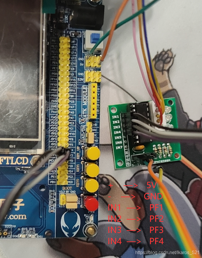
接线
+    —>   5V
-    —>   GND
IN1  —>   PF1
IN2  —>   PF2
IN3  —>   PF3
IN4  —>   PF4
效果图
摇头模式
// 24 * 5.625 = 135
n = 24;
// 0.2 * 10 = 2
x = 10;
(顺n个5.625度 停顿x个0.1秒 逆n个5.625度 停顿x个0.1秒) 共0.2x秒

转圈模式1
// 0.1 * 5 = 0.5
y = 5;
(顺1圈,停顿y个0.1秒) 共0.1y秒

转圈模式2
// 0.1 * 0 = 0
z = 0;
(逆1圈,停顿z个0.1秒) 共0.1z秒

自定义模式

核心代码
main.c
#include "led.h"
#include "delay.h"
#include "key.h"
#include "sys.h"
#include "beep.h"
#include "step.h"
#include "exti.h"

//IN4: PB6  d
//IN3: PB5  c
//IN2: PB4  b
//IN1: PB3  a

int main(void)
{
	// n个5.625度
	u8 n = 0;
	// 停顿x,y,z个0.1秒
	u8 x = 0, y = 0, z = 0;
	u8 i = 0;
	delay_init(); //延时函数初始化
	LED_Init();	  //初始化与LED连接的硬件接口
	BEEP_Init();  //初始化蜂鸣器端口
	EXTIX_Init(); // 初始化外部中断输入
	Step_Motor_GPIO_Init(); // 步进电机初始化

	LED0 = 0;
	BEEP = 0;

	// 24 * 5.625 = 135
	n = 24;
	// 0.2 * 10 = 2
	x = 10;
	// 0.1 * 5 = 0.5
	y = 5;
	// 0.1 * 0 = 0
	z = 0;

	while (1)
	{
		if(1 == mode) // 摇头模式 (顺n个5.625度 停顿x个0.1秒 逆n个5.625度 停顿x个0.1秒) 共0.2x秒
		{
			motor_circle(n, 0, 2);
			for(i = 0; i < x; i++)
			{
				delay_ms(100);
			}
			motor_circle(n, 1, 2);
			for(i = 0; i < x; i++)
			{
				delay_ms(100);
			}
		}
		else if(2 == mode) // 转圈模式1 (顺1圈,停顿y个0.1秒) 共0.1y秒
		{
			motor_circle(64, 0, 2);
			for(i = 0; i < y; i++)
			{
				delay_ms(100);
			}
		}
		else if(3 == mode) // 转圈模式2 (逆1圈,停顿z个0.1秒) 共0.1z秒
		{
			motor_circle(64, 1, 2);
			for(i = 0; i < z; i++)
			{
				delay_ms(100);
			}
		}
		else if(4 == mode) // 自定义模式 (自行修改代码) 共3.5秒
		{
			motor_circle(1, 0, 2);
			delay_ms(500);
			motor_circle(2, 0, 2);
			delay_ms(500);
			motor_circle(4, 0, 2);
			delay_ms(500);
			motor_circle(8, 0, 2);
			delay_ms(500);
			motor_circle(16, 0, 2);
			delay_ms(500);
			motor_circle(32, 0, 2);
			delay_ms(500);
			motor_circle(64, 0, 2);
			delay_ms(500);
		}
		else // 不工作模式 共0.5秒
		{
			delay_ms(500);
		}

		LED0 = !LED0;
	}
}
step.h
#ifndef  __STEP_H__
#define __STEP_H__

#include "stm32f10x.h"

void Step_Motor_GPIO_Init(void);
/*
	功能:转1/64圈
	步距角5.625 360/5.625=64 减速比1/64
	故64*64个脉冲转一圈
	n 圈数
	direction 方向 1正转 非1反转
	delay delay时长 >= 2
*/
void motor_circle(int n, int direction, int delay);

#endif
step.c
#include "sys.h"
#include "delay.h"
#include "step.h"

//IN4: PF4  d
//IN3: PF3  c
//IN2: PF2  b
//IN1: PF1  a

u8 forward[4] = {0x03,0x06,0x0c,0x09}; // 正转
u8 reverse[4]= {0x03,0x09,0x0c,0x06}; // 反转

//引脚初始化
void Step_Motor_GPIO_Init(void)
{
    GPIO_InitTypeDef GPIO_InitStructure;
    RCC_APB2PeriphClockCmd(RCC_APB2Periph_GPIOF, ENABLE);

    GPIO_InitStructure.GPIO_Mode = GPIO_Mode_Out_PP;
    GPIO_InitStructure.GPIO_Speed = GPIO_Speed_50MHz;
    GPIO_InitStructure.GPIO_Pin = GPIO_Pin_4|GPIO_Pin_3|GPIO_Pin_2|GPIO_Pin_1;
    GPIO_Init(GPIOF, &GPIO_InitStructure);
}

//引脚映射
void SetMotor(unsigned char InputData)
{
	if(InputData == 0x03)
	{
		GPIO_SetBits(GPIOF,GPIO_Pin_1);
		GPIO_SetBits(GPIOF,GPIO_Pin_2);
		GPIO_ResetBits(GPIOF,GPIO_Pin_3);
		GPIO_ResetBits(GPIOF,GPIO_Pin_4);
	}
	else if(InputData == 0x06)
	{
		GPIO_ResetBits(GPIOF,GPIO_Pin_1);
		GPIO_SetBits(GPIOF,GPIO_Pin_2);
		GPIO_SetBits(GPIOF,GPIO_Pin_3);
		GPIO_ResetBits(GPIOF,GPIO_Pin_4);
	}
	else if(InputData == 0x09)
	{
		GPIO_SetBits(GPIOF,GPIO_Pin_1);
		GPIO_ResetBits(GPIOF,GPIO_Pin_2);
		GPIO_ResetBits(GPIOF,GPIO_Pin_3);
		GPIO_SetBits(GPIOF,GPIO_Pin_4);
	}
	else if(InputData == 0x0c)
	{
		GPIO_ResetBits(GPIOF,GPIO_Pin_1);
		GPIO_ResetBits(GPIOF,GPIO_Pin_2);
		GPIO_SetBits(GPIOF,GPIO_Pin_3);
		GPIO_SetBits(GPIOF,GPIO_Pin_4);
	}
	else if(InputData == 0x00)
	{
		GPIO_ResetBits(GPIOF,GPIO_Pin_1);
		GPIO_ResetBits(GPIOF,GPIO_Pin_2);
		GPIO_ResetBits(GPIOF,GPIO_Pin_3);
		GPIO_ResetBits(GPIOF,GPIO_Pin_4);
	}
}

/*
	功能:转1/64圈
	步距角5.625 360/5.625=64 减速比1/64
	故64*64个脉冲转一圈
	n 圈数
	direction 方向 1正转 非1反转
	delay delay时长ms >= 2
*/
void motor_circle(int n, int direction, int delay)
{
    int i, j;
    for(i = 0; i < n * 8; i++)
    {
		for(j = 0; j < 4; j++)
		{
			if(1 == direction)
			{
				SetMotor(0x00);
				SetMotor(forward[j]);
			}
			else
			{
				SetMotor(0x00);
				SetMotor(reverse[j]);
			}

			delay_ms(delay > 2 ? delay : 2);
		}
    }
}
exti.h
#ifndef __EXTI_H
#define __EXIT_H
#include "sys.h"

// 工作模式标志位
extern u8 mode;

void EXTIX_Init(void);//外部中断初始化
#endif
exti.c
#include "exti.h"
#include "led.h"
#include "key.h"
#include "delay.h"
#include "usart.h"
#include "beep.h"
#include "exti.h"
#include "step.h"

u8 mode = 0;

//外部中断0服务程序
void EXTIX_Init(void)
{
    EXTI_InitTypeDef EXTI_InitStructure;
    NVIC_InitTypeDef NVIC_InitStructure;

    KEY_Init();	 //	按键端口初始化

    RCC_APB2PeriphClockCmd(RCC_APB2Periph_AFIO,ENABLE);	//使能复用功能时钟

    //GPIOE.3	  中断线以及中断初始化配置 下降沿触发 //KEY1
    GPIO_EXTILineConfig(GPIO_PortSourceGPIOE,GPIO_PinSource3);
    EXTI_InitStructure.EXTI_Line=EXTI_Line3;
    EXTI_InitStructure.EXTI_Mode = EXTI_Mode_Interrupt;
    EXTI_InitStructure.EXTI_Trigger = EXTI_Trigger_Falling;
    EXTI_Init(&EXTI_InitStructure);	  	//根据EXTI_InitStruct中指定的参数初始化外设EXTI寄存器

    //GPIOE.4	  中断线以及中断初始化配置  下降沿触发	//KEY0
    GPIO_EXTILineConfig(GPIO_PortSourceGPIOE,GPIO_PinSource4);
    EXTI_InitStructure.EXTI_Line=EXTI_Line4;
    EXTI_Init(&EXTI_InitStructure);	  	//根据EXTI_InitStruct中指定的参数初始化外设EXTI寄存器


    //GPIOA.0	  中断线以及中断初始化配置 上升沿触发 PA0  WK_UP
    GPIO_EXTILineConfig(GPIO_PortSourceGPIOA,GPIO_PinSource0);

    EXTI_InitStructure.EXTI_Line=EXTI_Line0;
    EXTI_InitStructure.EXTI_Trigger = EXTI_Trigger_Rising;
    EXTI_Init(&EXTI_InitStructure);		//根据EXTI_InitStruct中指定的参数初始化外设EXTI寄存器


    NVIC_InitStructure.NVIC_IRQChannel = EXTI0_IRQn;			//使能按键WK_UP所在的外部中断通道
    NVIC_InitStructure.NVIC_IRQChannelPreemptionPriority = 0x02;	//抢占优先级2,
    NVIC_InitStructure.NVIC_IRQChannelSubPriority = 0x03;					//子优先级3
    NVIC_InitStructure.NVIC_IRQChannelCmd = ENABLE;								//使能外部中断通道
    NVIC_Init(&NVIC_InitStructure);

    NVIC_InitStructure.NVIC_IRQChannel = EXTI3_IRQn;			//使能按键KEY1所在的外部中断通道
    NVIC_InitStructure.NVIC_IRQChannelPreemptionPriority = 0x02;	//抢占优先级2
    NVIC_InitStructure.NVIC_IRQChannelSubPriority = 0x01;					//子优先级1
    NVIC_InitStructure.NVIC_IRQChannelCmd = ENABLE;								//使能外部中断通道
    NVIC_Init(&NVIC_InitStructure);  	  //根据NVIC_InitStruct中指定的参数初始化外设NVIC寄存器

    NVIC_InitStructure.NVIC_IRQChannel = EXTI4_IRQn;			//使能按键KEY0所在的外部中断通道
    NVIC_InitStructure.NVIC_IRQChannelPreemptionPriority = 0x02;	//抢占优先级2
    NVIC_InitStructure.NVIC_IRQChannelSubPriority = 0x00;					//子优先级0
    NVIC_InitStructure.NVIC_IRQChannelCmd = ENABLE;								//使能外部中断通道
    NVIC_Init(&NVIC_InitStructure);  	  //根据NVIC_InitStruct中指定的参数初始化外设NVIC寄存器

}

//外部中断0服务程序
void EXTI0_IRQHandler(void)
{
    delay_ms(10);//消抖
    if(WK_UP==1)	 	 //WK_UP按键 工作模式切换
    {
        mode++;
		mode = mode > 4 ? 0 : mode;
    }
    EXTI_ClearITPendingBit(EXTI_Line0); //清除LINE0上的中断标志位
}


//外部中断3服务程序
void EXTI3_IRQHandler(void)
{
    delay_ms(10);//消抖
    if(KEY1==0)	 //按键KEY1
    {
        // 逆时针转5.625度
        motor_circle(1, 1, 2);
		LED1 = !LED1;
    }
    EXTI_ClearITPendingBit(EXTI_Line3);  //清除LINE3上的中断标志位
}

void EXTI4_IRQHandler(void)
{
    delay_ms(10);//消抖
    if(KEY0==0)	 //按键KEY0
    {
		// 顺时针转5.625度
        motor_circle(1, 0, 2);
		LED1 = !LED1;
    }
    EXTI_ClearITPendingBit(EXTI_Line4);  //清除LINE4上的中断标志位
}

 浙公网安备 33010602011771号