后端基础——详解setup与hold
一,基础
在数字集成电路中,通常用建立时间(setup time)、保持时间(hold time)、传输延迟时间(propagation delay time)、最高时钟频率(maximum clock frequency)等几个参数具体描述触发器的动态特性。
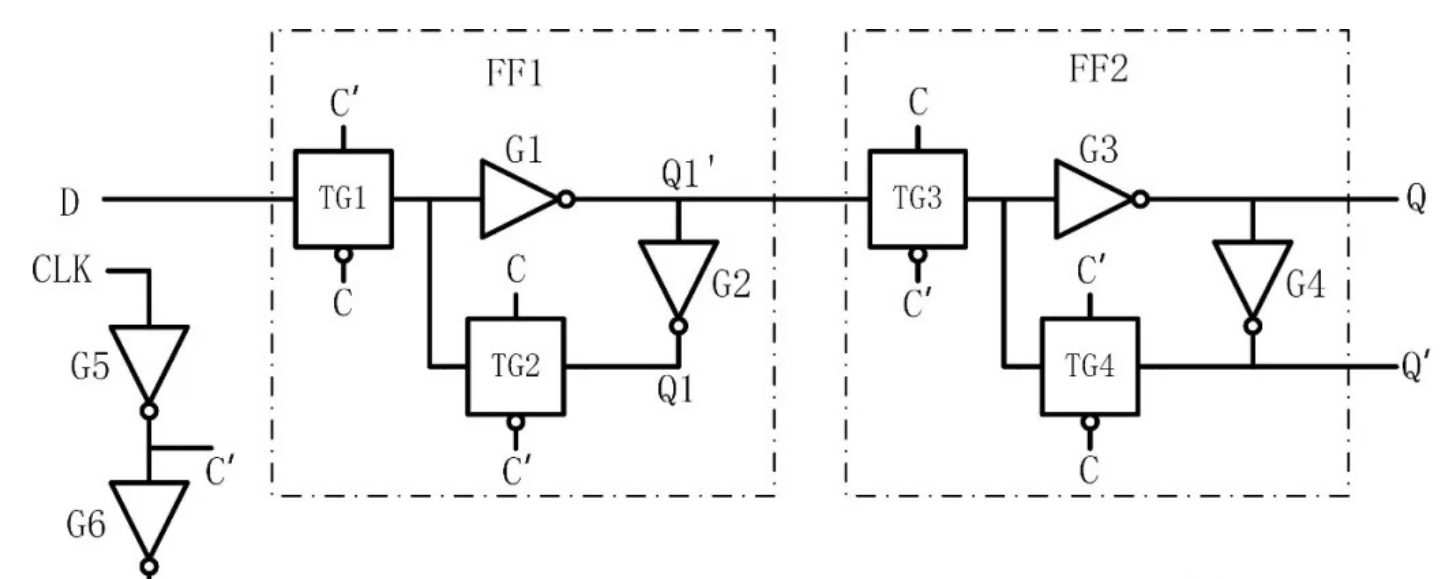
以一个边沿D触发器为例
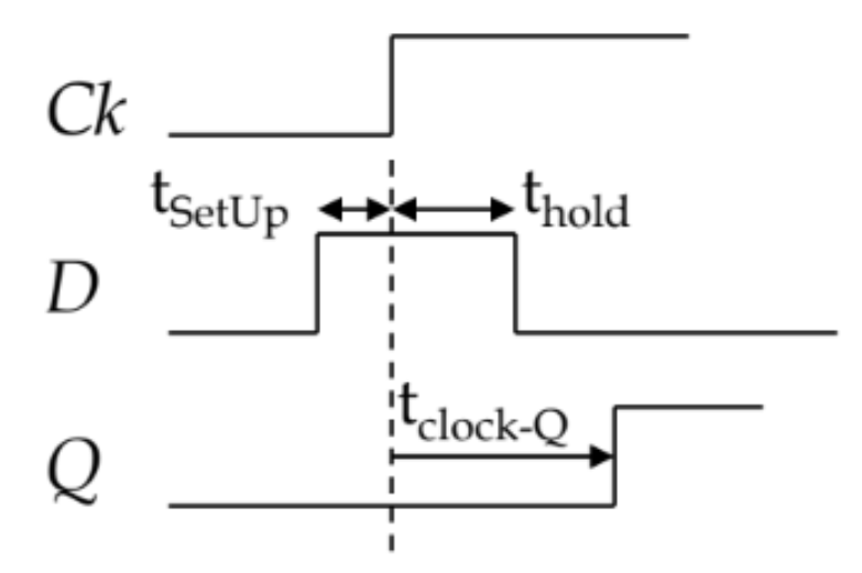
- 建立时间(setup time)tsu
建立时间是指输入信号应当先于时钟信号CLK动作到达的时间。为了保证触发器可靠地翻转,在C和C'状态改变以前FF1中Q1的状态必须稳定地建立起来,使Q1=D。由于加到D端的输入信号需要经过传输门TG1和反相器G1、G2才能到达Q1端,延迟时间为3*td;而在CLK的上升沿到达后,只需经过反相器G5的传输延迟时间C'的状态即开始改变,延迟时间为1*td,因此D端的输入信号必须先于CLK的上升沿至少2*td的时间到达,故tsu=2*td. - 保持时间(hold time)th
保持时间是指时钟信号CLK动作到达后,输入信号仍然需要保持不变的时间。由图可见,在C和C'改变状态使TG1变为截止、TG2变为导通之前,D端的输入信号应当保持不变。为此,至少在CLK上升沿到达后2*td的时间内输入信号应当保持不变,即保持时间应当为th=2*td.换句话说:当信号从0变为1的过程中,在一段很短的时间内,所有传输门都可能导通,若此时D端信号发生变化而CLK的transition比较慢,则会发生新值覆盖旧值而导致信号错误的现象。因此,D段信号需要在传输门完成开/关过程中保持稳定,此即为hold的物理意义,也是timing report中library hold time代表的含义。
二,setup和hold应该维持在什么范围
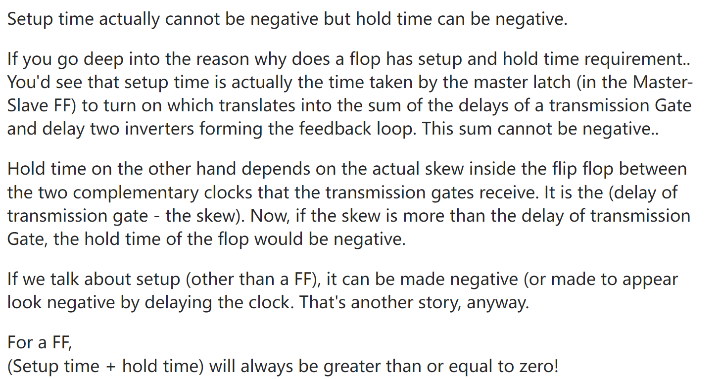
结论:setup通常情况下应当保持为正,hold可以允许为负,但setup+hold应当为正数
Tskew1+Tcq+Tlogic+Tsetup>=Tskew2+Thold
Thold为负,则Tskew2有较大的变化空间。
来看一个解释:
另一个解释:
Setup Time: and Hold Time: If the data or signal changes just before and after the active edge of the clock respectively then we say that setup time/ hold time has been violated.
Causes for Setup Time: Setup violations can happen as a result of slow conditions (slow process, high temperature) leading to signals arriving too late in the clock period.
Strategy to Fix Setup Time: Reduce Delay.
*As a RTL Design Engineer*:
- If the RTL code is a FSM , change the states of a FSM to one hot encode or grey code. If only one bit is changing at a time, it is a good chance that it would be faster and less delay.
- Prefer to use case statement over if else. Case statements and if else statements would have the same functionality but synthesis captures them differently. If there are multiple branch conditions, case statements (which is a mux) would be faster than synthesized if else (which would be priority encoder).
- Achieve Parallelism in RTL Serial Codes elongate the critical path and that is BAD. If we can split large serial operation in to multiple parallel operations then it is simple to meet timing of small individual units.
*As a Physical Design Engineer*:
- Make use of macros Each industry I believe would be having specific macros available. These are usually best optimized cells.
- Try to make use of libraries derived from NAND logic. Since , NAND and NOR are universal gates and NAND being faster than NOR they could be utilized to reduce delay. For example: if NAND is followed by a latch, simply use latch-NAND driver.
- Increase Wire Thickness (reduces resistance) and increase the spacing between wires (decreases coupling capacitance).
- Use Cells with lower Threshold Voltages: Cells with lower threshold voltage have lesser transition times which makes the propagation of logic faster.
- Restructuring/Re-timing would be the best way to optimize the logic. Based upon the placement of data path logic cells, you can decide either to combine simple logic gates into a complex gate, or split a multi-stage cell into simpler logic gates.
- A cell with better drive strength can charge the load capacitance quickly, resulting in lesser propagation delay. So make sure you cell has better drive strength. (Traditionally , I believe larger cells should be having more driving strength).
- For a critical path with a capture flop and a launch flop , try to ensure that the clock at the capture flop comes late or the clock at the launch flop comes early. This will give some extra timing and will be able to relax any violations we would be facing.
Alternative Explanation (for point 7th) : Positive skew helps improve the setup slack. So, to fix setup violation, we may either choose to increase the clock latency of capturing flip-flop, or decrease the clock latency of launching flip-flop.
I am happy to provide diagrammatic explanations as well, if you are interested in explanation with diagrams do comment it.
Causes for Hold Time Violations: Hold violations can happen as a result of fast conditions (fast process, low temperature) leading to signals arriving too early in the clock period.
Strategy to Fix Hold Time:
*As a Physical Design Engineer*
- Insert buffers. The timing path where hold violation is occurring, if the delay is increased due to these buffers, then it shall ultimately lead to positive slack thereby improving the chances of hold time being met.
- Use data-path cells with higher threshold voltages: If you have multiple varieties of cells with variable threshold voltages, then the cells with higher threshold voltage will have higher transition times. This reduces the chances of the hold time being violated.
- Lock up Latches: If we some how try to separate the launching edge and capturing edge by a phase then it will relax the timing path and improves the chances of hold time being met. [Image shown at the last]
- A positive skew degrades hold timing and a negative skew aids hold timing. So, if a data-path is violating, we can either decrease the latency of capturing flip-flop or increase the clock latency of launching flip-flop.
Alternative explanation for last point: For a capture and launch flop, if the clock at the launch flop is made to arrive late or the clock at the capture flop is made to arrive early then the chances of hold time being violated is reduced.

 浙公网安备 33010602011771号