
1software flow diagram
As we know, Embedded design is the core of Electronic Product Design。
Digital Timer Operation:
IMPORTANT: Remember to observe all safety warnings when operating the heater on auto setting,
either attended or unattended. The timer allows you to select ‘AUTO’, ‘MANUAL ON’ or ’MANUAL
OFF’ operation mode by pressing the ‘‘MODE’’ button until the required mode appears on the timer
display. ‘AUTO’ mode allows the heater to switch ON and OFF according to a set daily program
everyday (see ‘Setting Programs’ section below). ‘MANUAL ON’ mode allows power to the heater
uninterrupted by the program settings. ‘MANUAL OFF’ mode switches off all heater operation
completely.
Key Lock:
Inital Operation:
Setting Current Time:
setting Programmes:
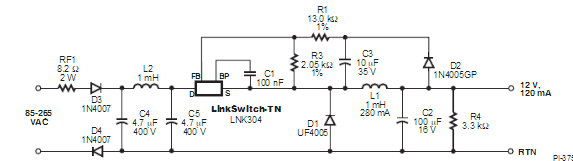
2.power scheme
Our product applied to home burner, Which simply means, AC 230V foolow the relay ,mcu control realy stwitch.
and lcd show the seting ,and Push button Settings。
firstly. the power scheme is OTG 。 We choice lnk306 , Lowest Component Count, Energy-Efficient Off-Line Switcher IC, and output 12v,this voltage be use of relay power.
Then, we need 7805 or 7803 ,to generate 5v and 3.3v to driver the IC of circuit.
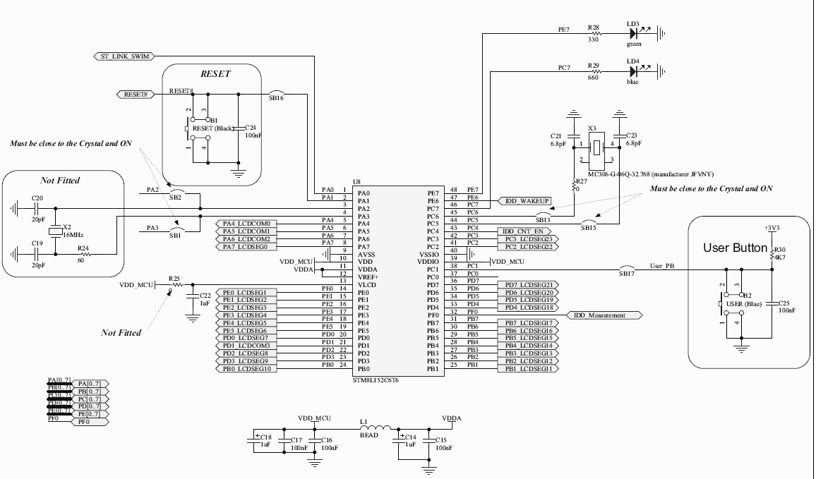
3 mcu scheme
The STM8L-DISCOVERY helps you to discover the STM8L ultralow power features and to
develop and share your applications. It is based on an STM8L152C6T6 and includes an
ST-Link embedded debug tool interface, LCD (24 segments, 4 commons), LEDs and push
buttons.