网络实验 交换机自身互联
题目:拓扑如下,一台华三交换自身连了三条链路,另外连到两台PC,要求PC01和PC02之间互访的流量必须经过交换机上自身相连的三条链路。
要求三种方式实现:
1、交换机纯二层转发;
2、交换机做三层转发,通过VRF隔离;
3、交换机做三层转发,通过策略路由让流量绕行,不能配置VRF。
实验要求:完全清空交换机的配置,拨掉全部连线,每一种方案要求在30分钟内调试完成。
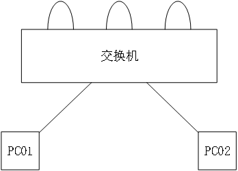
| 注:三条交换机自身相连的链路接口为 g1/0/1--g1/0/6,交换机与pc相连的链路接口为g1/0/23--g1/0/24
方式一:交换机纯二层转发
undo stp global enable    ###关闭生成树,使能环路
vlan 10 20 30 40          ###划分不同VLAN
int g1/0/1
port access vlan 10
int g1/0/2
port access vlan 20
int g1/0/3
port access vlan 20
int g1/0/4
port access vlan 30
int g1/0/5
port access vlan 30
int g1/0/6
port access vlan 40
int g1/0/23
port access vlan 10
int g1/0/24
port access vlan 40
方式二:交换机做三层转发,通过VRF隔离
undo stp global enable        ###关闭生成树,使能环路
vlan 10 20 30 40 50 60           ###划分不同VLAN
使能A B C D四个VPN实例
ip vpn-instance A
 address-family ipv4             ####允许IPv4地址通过
 quit
ip vpn-instance B
 address-family ipv4
 quit
ip vpn-instance C
 address-family ipv4
 quit
ip vpn-instance D
 address-family ipv4
 quit
quit
在Vlanif接口/物理接口中绑定VPN实例并分配IP地址
interface Vlan-interface10
 ip binding vpn-instance A
 ip address 100.69.10.1 255.255.255.0
interface Vlan-interface20
 ip binding vpn-instance B
 ip address 100.69.10.2 255.255.255.0
interface Vlan-interface30
 ip binding vpn-instance B
 ip address 100.69.30.1 255.255.255.0
interface Vlan-interface40
 ip binding vpn-instance C
 ip address 100.69.30.2 255.255.255.0
interface Vlan-interface50
 ip binding vpn-instance C
 ip address 100.69.50.1 255.255.255.0
interface Vlan-interface60
 ip binding vpn-instance D
 ip address 100.69.50.2 255.255.255.0
interface GigabitEthernet1/0/23
 port link-mode route             ### 接口启用三层模式
 ip binding vpn-instance A
 ip address 100.69.23.254 255.255.255.0
interface GigabitEthernet1/0/24
 port link-mode route              ### 接口启用三层模式
 ip binding vpn-instance D
 ip address 100.69.24.254 255.255.255.0
将vlan加入至接口
interface GigabitEthernet1/0/1
 port link-mode bridge
 port access vlan 10
interface GigabitEthernet1/0/2
 port link-mode bridge
 port access vlan 20
interface GigabitEthernet1/0/3
 port link-mode bridge
 port access vlan 30
interface GigabitEthernet1/0/4
 port link-mode bridge
 port access vlan 40
interface GigabitEthernet1/0/5
 port link-mode bridge
 port access vlan 50
interface GigabitEthernet1/0/6
 port link-mode bridge
 port access vlan 60
quit
配置VPN实例的路由
ip route-static vpn-instance A 100.69.24.0 24 100.69.10.2
ip route-static vpn-instance B 100.69.23.0 24 100.69.10.1
ip route-static vpn-instance B 100.69.24.0 24 100.69.30.2
ip route-static vpn-instance C 100.69.23.0 24 100.69.30.1
ip route-static vpn-instance C 100.69.24.0 24 100.69.50.2
ip route-static vpn-instance D 100.69.23.0 24 100.69.50.1
方式三:交换机做三层转发,通过策略路由让流量绕行,不能配置VRF
undo stp global enable    ###关闭生成树,使能环路
ip ttl-expires enable          ###开启ttl回显,用于pc端tracert回显
vlan 10 20 30 40 50 60
创建ACL策略,3000为目的地址为100.69.24.0/24的规则、3100为目的地址为100.69.23.0/24的规则
acl advanced 3000
 rule 0 permit ip destination 100.69.24.0 0.0.0.255
quit
acl advanced 3100
 rule 0 permit ip destination 100.69.23.0 0.0.0.255
quit
将ACL策略规则绑定至策略路由中并指定下一跳
| 下一跳为出接口所在同网段的IP地址(非出接口地址),目的是为报文在连接交换机的链路的一端可以转发出去,并可以发送至另一端。(后面需要配置静态ARP才能实现报文在出接口接收到,目的地址为链路一端出接口的IP地址,目的mac为链路另一端进接口Vlanif接口的mac地址)
policy-based-route 23 permit node 0
 if-match acl 3000
 apply next-hop 100.69.10.2
policy-based-route 20 permit node 0
 if-match acl 3000
 apply next-hop 100.69.30.2
policy-based-route 40 permit node 0
 if-match acl 3000
 apply next-hop 100.69.50.2
policy-based-route 24 permit node 0
 if-match acl 3100
 apply next-hop 100.69.60.2
policy-based-route 50 permit node 0
 if-match acl 3100
 apply next-hop 100.69.40.2
policy-based-route 30 permit node 0
 if-match acl 3100
 apply next-hop 100.69.20.2
Vlanif接口中配置地址
interface Vlan-interface10
 ip address 100.69.10.1 255.255.255.0
interface Vlan-interface20
 ip address 100.69.20.1 255.255.255.0
 ip policy-based-route 20
interface Vlan-interface30
 ip address 100.69.30.1 255.255.255.0
 ip policy-based-route 30
interface Vlan-interface40
 ip address 100.69.40.1 255.255.255.0
 ip policy-based-route 40
interface Vlan-interface50
 ip address 100.69.50.1 255.255.255.0
 ip policy-based-route 50
interface Vlan-interface60
 ip address 100.69.60.1 255.255.255.0
23 24接口的模式更改为三层模式,直接配置地址
interface GigabitEthernet1/0/23
 port link-mode route
 ip address 100.69.23.254 255.255.255.0
 ip policy-based-route 23
interface GigabitEthernet1/0/24
 port link-mode route
 ip address 100.69.24.254 255.255.255.0
 ip policy-based-route 24
将vlan加入至物理接口
interface GigabitEthernet1/0/1
 port link-mode bridge
 port access vlan 10
interface GigabitEthernet1/0/2
 port link-mode bridge
 port access vlan 20
interface GigabitEthernet1/0/3
 port link-mode bridge
 port access vlan 30
interface GigabitEthernet1/0/4
 port link-mode bridge
 port access vlan 40
interface GigabitEthernet1/0/5
 port link-mode bridge
 port access vlan 50
interface GigabitEthernet1/0/6
 port link-mode bridge
 port access vlan 60
quit
配置静态ARP
| 静态ARP格式说明:ip route-static vpn-instance [实例名称] [下一跳地址] [出接口的vlan] [出接口 ]
 arp static 100.69.10.2 00be-d538-61ba 10 GigabitEthernet1/0/1
 arp static 100.69.20.2 00be-d538-61b0 20 GigabitEthernet1/0/2
 arp static 100.69.30.2 00be-d538-61ae 30 GigabitEthernet1/0/3
 arp static 100.69.40.2 00be-d538-61c4 40 GigabitEthernet1/0/4
 arp static 100.69.50.2 00be-d538-61c2 50 GigabitEthernet1/0/5
 arp static 100.69.60.2 00be-d538-61b8 60 GigabitEthernet1/0/6

 浙公网安备 33010602011771号