RT Thread的SPI设备驱动框架的使用以及内部机制分析
注释:这是19年初的博客,写得很一般,理解不到位也不全面。19年末得空时又重新看了RTThread的SPI和GPIO,这次理解得比较深刻。有时间时再整理上传。
-----------------------------------------------------------------------------------------------------------------------------------------------------------------------------------------------
使用SPI设备驱动框架操作max32865读取PT100的例子程序:
#include "board.h"
#include "drv_spi.h"
#include "max31865.h"

#define TempModule_SPI_BUS_NAME "spi2" // 对应硬件
#define TempModule_DEVICE_NAME "spi20" // 这个名字无所谓 不需要对应硬件

#define CS_PIN 28

static struct stm32_hw_spi_cs spi_cs;

static struct TempModule_device_ TempModule_device;


int rt_hw_TempModule_Config(void)
{
rt_err_t res;

struct rt_spi_device * rt_spi_device;

rt_pin_mode(CS_PIN, PIN_MODE_OUTPUT);

spi_cs.GPIOx = GPIOB;
spi_cs.GPIO_Pin = GPIO_PIN_12;

// 这个要根据SPI设备名字 来 查找 设备 功能1: 把spi20挂到spi2上
res = rt_hw_spi_device_attach(TempModule_SPI_BUS_NAME, TempModule_DEVICE_NAME, spi_cs.GPIOx, spi_cs.GPIO_Pin);
if( res == RT_EOK )
{
rt_kprintf("\n rt_hw_spi_device_attach(), OK! \r\n");
}

rt_spi_device = (struct rt_spi_device *)rt_device_find(TempModule_DEVICE_NAME);

TempModule_device.Handle_TempModule_spibus = rt_spi_device;

if( rt_spi_device == RT_EOK )
{
rt_kprintf("\n rt_device_find OK! \r\n");
}

/* config spi */
{
struct rt_spi_configuration cfg;
cfg.data_width = 8;
cfg.mode = RT_SPI_MASTER | RT_SPI_MODE_1 | RT_SPI_MSB;
cfg.max_hz = 1 * 30 *1000; /* SPI max 42MHz,ssd1351 4-wire spi */

res = rt_spi_configure(rt_spi_device, &cfg);

if( res == RT_EOK )
{
rt_kprintf("\n rt_spi_configure(), OK! \r\n");
}
}

return RT_EOK;
}


static int rt_hw_TempModule_init(void)
{
rt_hw_TempModule_Config();

// IO 方向
// rt_pin_mode(TempModuleNCS_PIN, PIN_MODE_OUTPUT);

// 中断

// IO初值设置
TempModule_NCS_H();
rt_kprintf("rt_hw_TempModule_init \r\n");
return 0;
}
INIT_PREV_EXPORT(rt_hw_TempModule_init);    /* 组件自动初始化 */


u8 TempModuleByte( u8 Sdata)
{
u8 Rdata = 0;
rt_enter_critical();
//    Sdata = 0x55;
// rt_spi_send_then_recv第一个形参:struct rt_spi_device *device;
// rt_spi_send_then_recv( TempModule_device.Handle_TempModule_spibus, &Sdata, (rt_size_t)1, &Rdata, (rt_size_t)1);
//Rdata = rt_spi_send(TempModule_device.Handle_TempModule_spibus, &Sdata, 1);

rt_spi_transfer(TempModule_device.Handle_TempModule_spibus, &Sdata, &Rdata, 1);

rt_exit_critical();
return Rdata;
}


void TempModuleWrite(u16 WrPara)
{
u8 tmp[2] = {0};

tmp[0]= WrPara>>8;
tmp[1]= WrPara&0xFF;

//    TempModuleByte(WrPara>>8);
//    TempModuleByte(WrPara&0xFF);

rt_spi_send(TempModule_device.Handle_TempModule_spibus, tmp, 2);
}


u8 TempModuleRead(u8 adr)
{
u8 tmp;

// TempModuleByte(adr);
// tmp = TempModuleByte(0xFF);

tmp = rt_spi_sendrecv8(TempModule_device.Handle_TempModule_spibus, adr);

return tmp;
}


float Get_tempture(void)
{
float temps;
uint16_t dtemp[2];
uint16_t data_temp;
dtemp[0]=TempModuleRead(0x1);
//    rt_kprintf("dtemp[0] = %d \r\n",dtemp[0]);

dtemp[1]=TempModuleRead(0x2);
//    rt_kprintf("dtemp[1] = %d \r\n",dtemp[1]);

data_temp=(dtemp[0]<<7)+(dtemp[1]>>1);//Get 15Bit DATA;
temps=data_temp;
temps=(temps*402)/32768;//Here is the rtd R value;
temps=(temps-100)/0.385055;//A gruad
return temps;
}
下面提出我的疑问:

网友提示:
ENV打开了 spix, 就会加载对应的drv 里面的注册函数。
我的理解:图YY
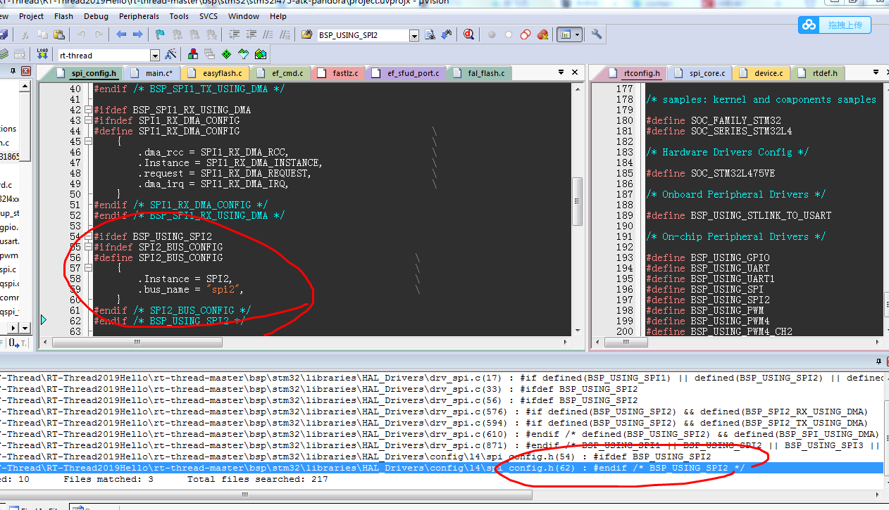
继续找,猜想注册spi2硬件的时候 肯定 会用到这个包含“spi2”字符串的SPI2_BUS_CONFIG信息。 《==== 接下来的目标转换为找到这个在哪注册的。
实测,“spi2”这个字符串一定要和硬件所使用的对应(其他文件内我还会配置硬件SPI2对应的IO口),为什么?
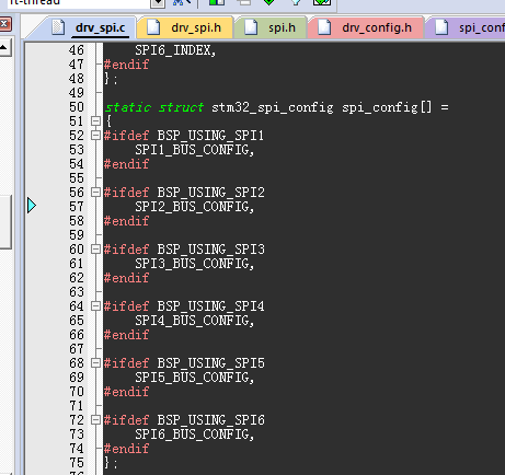
spi_config[]配置信息容器:
这个是个核心,如果一个SPIx的宏都没打开,那么这个数组的长度就是0. 待初始化的SPI总线的个数就是0.
可以通过数组的长度来计算需要初始化的SPI总线(spi1、spi2)的个数。
上述过程是由RTT的组件自动初始化技术:INIT_BOARD_EXPORT(负责硬件初始化的函数名); 完成。
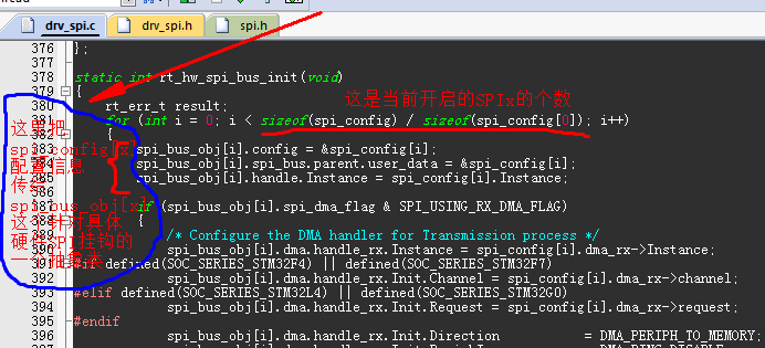
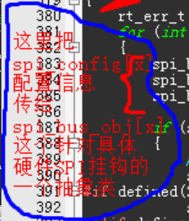
下图是 -- 图X:
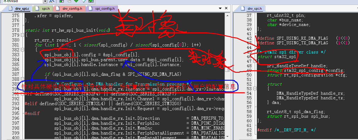
针对具体硬件SPI总线的抽象类也含有一份配置信息,可以用来存储用户的配置信息。
到这里,已经基本解决了上述的一个疑惑:针对硬件的spi2,是不是在软件里就是使用了 “spi2”这个字符串作为其名字? 答案是:是的。
到了这里,也就慢慢拓展开了SPI设备驱动框架的玩法。
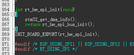
使用组件自动初始化技术调用 rt_hw_spi_bus_init()函数。
// 关于组件自动初始化技术,参考另外的博文。
https://mp.weixin.qq.com/s?__biz=MzAwMDUwNDgxOA==&mid=2652663356&idx=1&sn=779762953029c0e0946c22ef2bb0b754&chksm=810f28a1b678a1b747520ba3ee47c9ed2e8ccb89ac27075e2d069237c13974aa43537bff4fba&mpshare=1&scene=1&srcid=0111Ys4k5rkBto22dLokVT5A&pass_ticket=bGNWMdGEbb0307Tm%2Ba%2FzAKZjWKsImCYqUlDUYPZYkLgU061qPsHFESXlJj%2Fyx3VM#rd
知道了组件自动初始化,我们来看一下这个spi总线初始化的函数干了啥?
static int rt_hw_spi_bus_init(void)
{
rt_err_t result;
for (int i = 0; i < sizeof(spi_config) / sizeof(spi_config[0]); i++)
{
spi_bus_obj[i].config = &spi_config[i]; // 保存用户的配置信息,到单片机外设层面的硬件抽象层。用户在rt_config.h用使用宏开关打开配置信息。
spi_bus_obj[i].spi_bus.parent.user_data = &spi_config[i];
spi_bus_obj[i].handle.Instance = spi_config[i].Instance;
if (spi_bus_obj[i].spi_dma_flag & SPI_USING_RX_DMA_FLAG)
{
/* Configure the DMA handler for Transmission process */
spi_bus_obj[i].dma.handle_rx.Instance = spi_config[i].dma_rx->Instance;
#if defined(SOC_SERIES_STM32L4) || defined(SOC_SERIES_STM32G0)
spi_bus_obj[i].dma.handle_rx.Init.Request = spi_config[i].dma_rx->request;
#endif
spi_bus_obj[i].dma.handle_rx.Init.Direction = DMA_PERIPH_TO_MEMORY;
spi_bus_obj[i].dma.handle_rx.Init.PeriphInc = DMA_PINC_DISABLE;
spi_bus_obj[i].dma.handle_rx.Init.MemInc = DMA_MINC_ENABLE;
。。。
}。。。
}result = rt_spi_bus_register(&spi_bus_obj[i].spi_bus, spi_config[i].bus_name, &stm_spi_ops);
}return result;
}
对于rt_hw_spi_bus_init()函数,上文我们分析了其内部的一个重要部分,如图X所示。
我们再来看其内部的另一个重要部分,即rt_spi_bus_register这个注册函数。
对于rt_spi_bus_register有两条分析路线,
分支一: 最后一个形参,stm_spi_ops ,关注的是这是啥东西,能干嘛。我们要查找stm_spi_ops的定义。
分支二:rt_spi_bus_register函数本身,关注的是他执行了哪些动作。
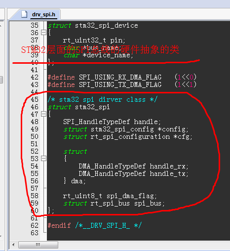 STM32层面的SPI总线的硬件抽象的类
下面,进行分支一的讨论:
static const struct rt_spi_ops stm_spi_ops =
{
.configure = spi_configure,
.xfer = spixfer,
};
static rt_err_t spi_configure (struct rt_spi_device *device, struct rt_spi_configuration *configuration) // 这里的形参们,用品红色来表示
{...
struct stm32_spi *spi_drv = rt_container_of(device->bus, struct stm32_spi, spi_bus); // 找到针对具体硬件SPI总线的抽象出来的类的对象
spi_drv->cfg = configuration;
return stm32_spi_init(spi_drv, configuration); // 将配置信息填入对应该SPI总线的硬件抽象层的类对象
}
static rt_err_t stm32_spi_init(struct stm32_spi *spi_drv, struct rt_spi_configuration *cfg)
{
RT_ASSERT(spi_drv != RT_NULL);
RT_ASSERT(cfg != RT_NULL);
SPI_HandleTypeDef *spi_handle = &spi_drv->handle; // 获取该硬件抽象层的类对象的详细信息
if (cfg->mode & RT_SPI_SLAVE)
{spi_handle->Init.Mode = SPI_MODE_SLAVE;}
else{spi_handle->Init.Mode = SPI_MODE_MASTER;}
if (cfg->mode & RT_SPI_3WIRE)
{spi_handle->Init.Direction = SPI_DIRECTION_1LINE;}
else{spi_handle->Init.Direction = SPI_DIRECTION_2LINES;}
... SPI_DATASIZE_8BIT;
... SPI_DATASIZE_16BIT;
... SPI_PHASE_2EDGE;
... SPI_POLARITY_LOW;
... SPI_NSS_SOFT;
... 省...略...不一一列举...
if (HAL_SPI_Init(spi_handle) != HAL_OK)
// 这里采用其他方法(stm32的HAL库函数),完成了一系列动作:对stm32单片机的底层寄存器的操作配置。达成了最终的目的。
{return RT_EIO;}
if (spi_drv->spi_dma_flag & SPI_USING_TX_DMA_FLAG)
{
HAL_DMA_Init(&spi_drv->dma.handle_tx);
__HAL_LINKDMA(&spi_drv->handle, hdmatx, spi_drv->dma.handle_tx);
/* NVIC configuration for DMA transfer complete interrupt */
HAL_NVIC_SetPriority(spi_drv->config->dma_tx->dma_irq, 0, 1);
HAL_NVIC_EnableIRQ(spi_drv->config->dma_tx->dma_irq);
}
__HAL_SPI_ENABLE(spi_handle); // 使能相应的SPI
//#define __HAL_SPI_ENABLE(__HANDLE__) SET_BIT((__HANDLE__)->Instance->CR1, SPI_CR1_SPE) 这是在操作底层硬件:单片机的底层寄存器
return RT_EOK;
}
通过分支一的讨论,我们知道了,stm_spi_ops具备配置单片机SPIx底层寄存器的全部能力,但是需要我们在外部给入参数,看上文的 品红色 示意处。
下面,进行分支二 rt_spi_bus_register 的讨论:
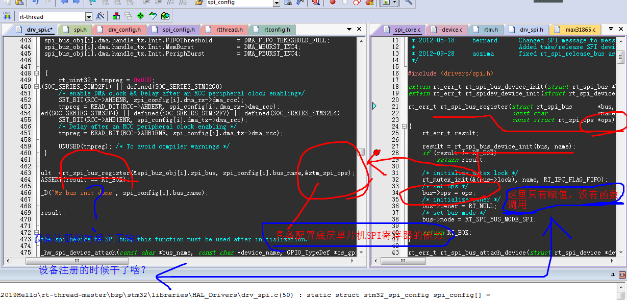
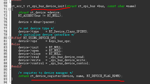
该设备注册函数:
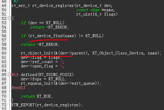
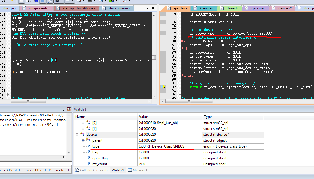
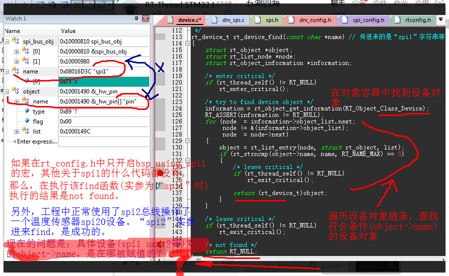
《==== 具体设备对应的object->name,是在哪被赋值的 ______?????_________
需要仿真跟一下,仿真也是有一定技巧和难度的,需要根据设备对象容器内的链表节点查找其他的对象。》
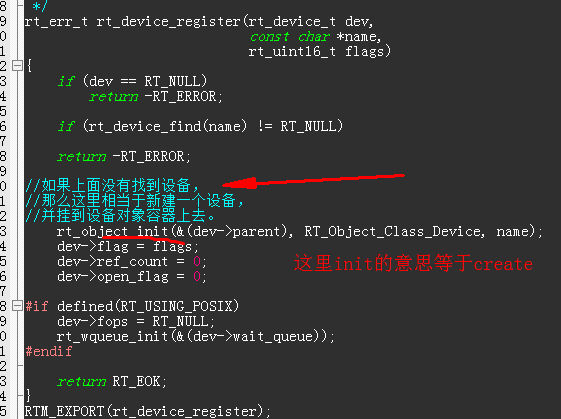 如果找不到,就新建一个设备挂上去。
未完待续。。。
这里面涉及的知识很美,很诱人。有思想,有抽象。
时间限制,有机会以后再接触RTT,再继续完善本文。


