使用 GD32F350 TIM16 生成 PWM
对于我来说,习惯或者思维方式上,使用一个不熟的 MCU,最快的是直接移植例程,我需要一路 PWM 用来控制步进电机,看了下 datasheet,GD32F350 的 TIM15、TIM16 有且只有一路输出,正好满足我的需求,看了下 SDK 自带例程中的 Timer 部分:
可惜没有 Timer15/Timer16 的例程,只能从现有的移植。看了下,决定参考 TIMER1_pwmout 。
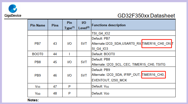
首先是初始化相关 IO 口,看了下手册,Timer16 PWM 输出可以有2个 IO:
参考手册上:
Function of complementary is for a pair of CHx_O and CHx_ON. Those two output signals
cannot be active at the same time.
这两个是互补输出,同一时间只能有一个可以使用。这里尝试下 TIMER16_CH0,即 PB9,初始化如下:
/*!
    \brief      configure the GPIO ports
    \param[in]  none
    \param[out] none
    \retval     none
  */
void gpio_config(void)
{
    /*Configure PB3 PB10 PB11(TIMER1 CH1 CH2 CH3) as alternate function*/
    gpio_mode_set(GPIOB, GPIO_MODE_AF, GPIO_PUPD_NONE, GPIO_PIN_9);
    gpio_output_options_set(GPIOB, GPIO_OTYPE_PP, GPIO_OSPEED_50MHZ,GPIO_PIN_9);

    gpio_af_set(GPIOB, GPIO_AF_2, GPIO_PIN_9);
}
然后定时器初始化改为:
void timer16_config(void)
{
    timer_oc_parameter_struct timer_ocintpara;
    timer_parameter_struct timer_initpara;

    rcu_periph_clock_enable(RCU_TIMER16);

    timer_deinit(TIMER16);

    /* TIMER1 configuration */

    timer_initpara.prescaler         = 107;

    timer_initpara.alignedmode       = TIMER_COUNTER_EDGE;
    timer_initpara.counterdirection  = TIMER_COUNTER_UP;
    timer_initpara.period            = 2000;
    timer_initpara.clockdivision     = TIMER_CKDIV_DIV1;
    timer_initpara.repetitioncounter = 0;
    timer_init(TIMER16,&timer_initpara);

    /* CH1,CH2 and CH3 configuration in PWM mode */
    timer_ocintpara.outputstate  = TIMER_CCX_ENABLE;
    timer_ocintpara.outputnstate = TIMER_CCXN_DISABLE;
    timer_ocintpara.ocpolarity   = TIMER_OC_POLARITY_HIGH;
    timer_ocintpara.ocnpolarity  = TIMER_OCN_POLARITY_HIGH;
    timer_ocintpara.ocidlestate  = TIMER_OC_IDLE_STATE_LOW;
    timer_ocintpara.ocnidlestate = TIMER_OCN_IDLE_STATE_LOW;

    timer_channel_output_config(TIMER16,TIMER_CH_0,&timer_ocintpara);

    timer_channel_output_pulse_value_config(TIMER16,TIMER_CH_0,1000);
    timer_channel_output_mode_config(TIMER16,TIMER_CH_0,TIMER_OC_MODE_PWM0);
    timer_channel_output_shadow_config(TIMER16,TIMER_CH_0,TIMER_OC_SHADOW_DISABLE);

    timer_interrupt_flag_clear(TIMER16, TIMER_INT_FLAG_CH0);
    /* enable the TIMER interrupt */
    timer_interrupt_enable(TIMER16, TIMER_INT_CH0);
    nvic_irq_enable(TIMER16_IRQn, 0,0);
    /* auto-reload preload enable */
    timer_auto_reload_shadow_enable(TIMER16);
    /* auto-reload preload enable */
    timer_enable(TIMER16);
}
跟例程相比,我添加了 timer16 中断设置:
    timer_interrupt_flag_clear(TIMER16, TIMER_INT_FLAG_CH0);
    /* enable the TIMER interrupt */
    timer_interrupt_enable(TIMER16, TIMER_INT_CH0);
    nvic_irq_enable(TIMER16_IRQn, 0,0);
中断函数为:
void TIMER16_IRQHandler(void)
{
    if(SET == timer_interrupt_flag_get(TIMER16, TIMER_INT_CH0)){
        /* clear channel 0 interrupt bit */
        printf("tim16 irq\r\n");
        timer_interrupt_flag_clear(TIMER16, TIMER_INT_CH0);
    }
}
程序中我添加了串口输出用作调试,如果进入中断,从串口输出 tim16 irq。
编译,然后运行,PB9 没输出,不过串口有输出 tim16 irq。说明 Tim16 是有在跑的,可以产生中断,不过没 PWM 输出
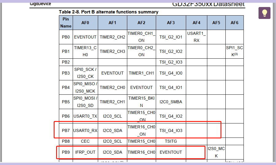
尝试了把 输出 IO 改为 PB7(TIMER16_CH0)也不行,
由于输出是低电平,PB7/PB9 都没外部上拉,尝试把 IO 配置从 GPIO_PUPD_NONE 改为 GPIO_PUPD_PULLUP 也不行。
由于 PB7/PB9 都有几个复用功能,会不会是端口复用设置问题呢?看了端口复用设置函数:
/*!
    \brief      set GPIO alternate function
    \param[in]  gpio_periph: GPIOx(x = A,B,C)
                only one parameter can be selected which is shown as below:
      \arg        GPIOx(x = A,B,C)
    \param[in]  alt_func_num: GPIO pin af function, please refer to specific device datasheet
                only one parameter can be selected which is shown as below:
      \arg        GPIO_AF_0: TIMER2, TIMER13, TIMER14, TIMER16, SPI0, SPI1, I2S0, CK_OUT, USART0, CEC,
                              IFRP, TSI, CTC, I2C0, I2C1, SWDIO, SWCLK
      \arg        GPIO_AF_1: USART0, USART1, TIMER2, TIMER14, I2C0, I2C1, IFRP, CEC
      \arg        GPIO_AF_2: TIMER0, TIMER1, TIMER15, TIMER16, I2S0
      \arg        GPIO_AF_3: TSI, I2C0, TIMER14
      \arg        GPIO_AF_4(port A,B only): USART1, I2C0, I2C1, TIMER13
      \arg        GPIO_AF_5(port A,B only): TIMER15, TIMER16, USBFS, I2S0
      \arg        GPIO_AF_6(port A,B only): CTC, SPI1
      \arg        GPIO_AF_7(port A,B only): CMP0, CMP1
    \param[in]  pin: GPIO pin
                one or more parameters can be selected which are shown as below:
      \arg        GPIO_PIN_x(x=0..15), GPIO_PIN_ALL
    \param[out] none
    \retval     none
*/
void gpio_af_set(uint32_t gpio_periph, uint32_t alt_func_num, uint32_t pin)
{
    uint16_t i;
    uint32_t afrl, afrh;

    afrl = GPIO_AFSEL0(gpio_periph);
    afrh = GPIO_AFSEL1(gpio_periph);

    for(i = 0U;i < 8U;i++){
        if((1U << i) & pin){
            /* clear the specified pin alternate function bits */
            afrl &= ~GPIO_AFR_MASK(i);
            afrl |= GPIO_AFR_SET(i,alt_func_num);
        }
    }

    for(i = 8U;i < 16U;i++){
        if((1U << i) & pin){
            /* clear the specified pin alternate function bits */
            afrh &= ~GPIO_AFR_MASK(i - 8U);
            afrh |= GPIO_AFR_SET(i - 8U,alt_func_num);
        }
    }

    GPIO_AFSEL0(gpio_periph) = afrl;
    GPIO_AFSEL1(gpio_periph) = afrh;
}
尝试了 GPIO_AF_0、GPIO_AF_2、GPIO_AF_5,也还是不行,
还怀疑了硬件上的问题,尝试了拉高拉低,都没问题,说明硬件上没问题,那就肯定是程序的问题了。
只能硬着头皮看文档了。看到 如下:
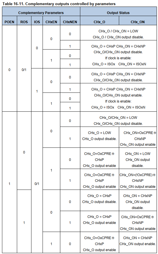
从上图可以看到,TIMER16_CH0、TIMER16_CH0N 输出是跟 POEN、ROS、IOS、CHxEN、CHxNEN这些寄存器有关,调试下,看这些寄存器有没有设置:
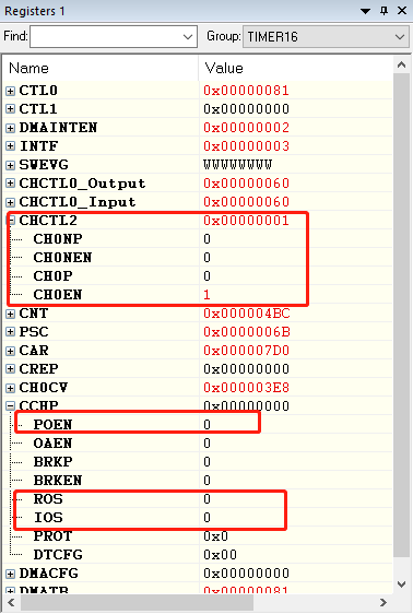
可以看到这些寄存器都没置位,根据手册,我一个一个位置位,一次修改如下:
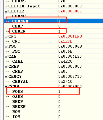
尝试后,端口有输出了,那就找方向了,肯定是这些寄存器没有配置,首先确认的是 POEN 位肯定要设置为 1,看了下 GD32F350 的 Timer 驱动源文件,看到如下函数:
/*!
    \brief      configure TIMER primary output function
    \param[in]  timer_periph: TIMERx(x=0,14..16)
    \param[in]  newvalue: ENABLE or DISABLE
    \param[out] none
    \retval     none
*/
void timer_primary_output_config(uint32_t timer_periph, ControlStatus newvalue)
{
    if(ENABLE == newvalue){
        TIMER_CCHP(timer_periph) |= (uint32_t)TIMER_CCHP_POEN;
    }else{
        TIMER_CCHP(timer_periph) &= (~(uint32_t)TIMER_CCHP_POEN);
    }
}
原来的例程中没调用到该函数,于是我把该函数添加到 timer 初始化部分:
timer_primary_output_config(TIMER16, ENABLE);
编译运行后,发现PB9 有输出。timer16 能输出 PWM 完整设置为:
void timer16_config(void)
{
    timer_oc_parameter_struct timer_ocintpara;
    timer_parameter_struct timer_initpara;

    rcu_periph_clock_enable(RCU_TIMER16);

    timer_deinit(TIMER16);

    /* TIMER1 configuration */

    timer_initpara.prescaler         = 107;

    timer_initpara.alignedmode       = TIMER_COUNTER_EDGE;
    timer_initpara.counterdirection  = TIMER_COUNTER_UP;
    timer_initpara.period            = 2000;
    timer_initpara.clockdivision     = TIMER_CKDIV_DIV1;
    timer_initpara.repetitioncounter = 0;
    timer_init(TIMER16,&timer_initpara);

    /* CH1,CH2 and CH3 configuration in PWM mode */
    timer_ocintpara.outputstate  = TIMER_CCX_ENABLE;
    timer_ocintpara.outputnstate = TIMER_CCXN_DISABLE;
    timer_ocintpara.ocpolarity   = TIMER_OC_POLARITY_HIGH;
    timer_ocintpara.ocnpolarity  = TIMER_OCN_POLARITY_HIGH;
    timer_ocintpara.ocidlestate  = TIMER_OC_IDLE_STATE_LOW;
    timer_ocintpara.ocnidlestate = TIMER_OCN_IDLE_STATE_LOW;

    timer_channel_output_config(TIMER16,TIMER_CH_0,&timer_ocintpara);

    timer_channel_output_pulse_value_config(TIMER16,TIMER_CH_0,1000);
    timer_channel_output_mode_config(TIMER16,TIMER_CH_0,TIMER_OC_MODE_PWM0);
    timer_channel_output_shadow_config(TIMER16,TIMER_CH_0,TIMER_OC_SHADOW_DISABLE);
    timer_primary_output_config(TIMER16, ENABLE);
    timer_interrupt_flag_clear(TIMER16, TIMER_INT_FLAG_CH0);
    /* enable the TIMER interrupt */
    timer_interrupt_enable(TIMER16, TIMER_INT_CH0);
    nvic_irq_enable(TIMER16_IRQn, 0,0);
    /* auto-reload preload enable */
    timer_auto_reload_shadow_enable(TIMER16);
    /* auto-reload preload enable */
    timer_enable(TIMER16);


    /*Configure PB3 PB10 PB11(TIMER1 CH1 CH2 CH3) as alternate function*/
    gpio_mode_set(GPIOB, GPIO_MODE_AF, GPIO_PUPD_NONE, GPIO_PIN_9);
    gpio_output_options_set(GPIOB, GPIO_OTYPE_PP, GPIO_OSPEED_50MHZ,GPIO_PIN_9);
    gpio_af_set(GPIOB, GPIO_AF_2, GPIO_PIN_9);
}
后来查了下文档,发现有IO复用设置的说明,PB7、PB9 部分如下:
这部分程序本来是在 GD32F350CB 上调的,后来把这程序修改了下,在 GD32F350G8 上也是可以用的,不过由于 GD32F350G8 上没有PB9,用的是 Timer15 来实现的,测试如下:
这个是 GD32F350 产生 PWM 脉冲用作 step 信号驱动 A4988 驱动步进电机
本文来自博客园,作者:哈拎,转载请注明原文链接:https://www.cnblogs.com/halin/p/16439762.html

 浙公网安备 33010602011771号