ARM-CPU DynamlQ技术及其power架构介绍
参考博文:http://www.diankeji.com/pingce/32006.html和http://blog.chinaaet.com/weiqi7777/p/5100063155
DynamlQ技术
一直以来,运算领域都在进行对更高性能的追求与突破。但是在移动运算领域,出于对便携性的妥协,性能受到能耗指标的钳制。在性能与能耗之间的取得微妙的平衡,让以智能手机为首的移动设备兼具优异的性能和出色的续航,是ARM工程师们长期以来面临的挑战。
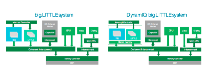
对此,2011年,ARM推出了全球第一的应用于手机市场的异构处理技术——big.LITTLE。该技术的架构包括一个高性能“大”CPU集群和一个高效率“小”CPU集群,它们之间通过一致互联实现连接。在该架构上运行的软件可以将正确的应用程序任务调度到正确的CPU上。
之后的几年,随着CPU不断推陈出新,软件层也得到了更新,引入了更加智能化的任务调度算法。然而,在此期间,硬件技术架构基础却基本保持不变,仍是大小若干个CPU集群。该技术在手机市场迅速得到应用。因此,如今基于ARMv8 的已出货安卓设备有三分之二都依靠 big.LITTLE优化功耗和性能。
为了进一步优化移动设备的性能与能耗,ARM近期发布了最新技术DynamIQ,因其对big.LITTLE技术未来发展影响深远,甚至可能大范围颠覆移动运算领域,而引起了科技行业和“技术爱好者”的强烈兴趣。
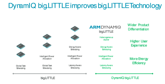
DynamIQ技术带来了一种可以改变异构处理格局的新型技术架构,它的做法是将大小两个集群合并,从而形成一个兼具大小CPU、完全集成化的CPU 集群。使用DynamIQ技术构建的big.LITTLE 设计被称为DynamIQ big.LITTLE。DynamIQ big.LITTLE技术在CPU集群中引入了智能化功耗功能,有助于在一定发热量之内最大限度地发挥性能。这就意味着数据处理能力和性能将会更加强大,在所有的应用程序都能创造更加丰富的体验。
DynamIQ big.LITTLE技术的到来, 将为消费者和移动设备厂商带来众多好处。
完全集成化的解决方案提供更广泛的产品差异化
消费者们一直期待智能手机的计算能力可以不断提高——对于每一款新上市的设备都是如此,无论是高端智能手机,还是入门级机型。客观地说,PokemonGo在 2016 年登陆手机市场之后一举成为人手必备的头号应用程序,即便在入门级智能手机上也一样。为了满足消费者对更高性能的需求,尤其是在对价格敏感的市场,SoC,系统级芯片内的产品差异化变得更加重要。
DynamIQ big.LITTLE系统中的新型集成式集群推出了可以拓宽产品差异化的全新组合。这些全新组合将会让“大”CPU越来越多地应用于中端市场,以便让性能水平相较于只有“小”CPU的传统设计有所提升。然而,可扩展性的范围并未到此为止。DynamIQ big.LITTLE 系统还允许在一个集群内将单个或成组的CPU调整到不同的性能和功耗点,从而让设计延伸出几乎无穷无尽的可能性。DynamIQ 提供的高度灵活性为价格敏感型市场创造了差异化机会。

单线程性能的提升带来更胜一筹的用户体验
虽然用户体验由于应用程序的不断发展而不断变化,但是有一件事情始终不变:用户体验在响应速度上十分依赖于单线程计算性能。诸如人工智能和增强现实之类的高级用途将对用户体验不断提出更高要求。然而,手机市场很快就提醒我们:发热量限制了设备能够实现的性能大小。热效率问题的范围已经超出了手机市场,它在汽车和笔记本电脑等其他市场也是不容忽视的一大因素。
为了克服该问题,big.LITTLE依靠动态电压/频率调节等技术,可以实现两个互补的性能域,其中每个性能域都能一致地调节电压和频率。而DynamIQ通过在单个集群中支持多个可配置的性能域,进一步发展了该技术。这些性能域由单个或多个ARM CPU组成,可以在性能和功耗方面进行调节,并获得更佳的精细程度,比以前的 Cortex-A 四核心集群在调节精度方面可获得多达4倍的提升。
该DynamIQ技术的特性意味着DynamIQ big.LITTLE系统能够在更严格的发热量限制之下发挥更多性能,从而延长性能的持续时间。此类系统还可以利用瞬时性能提升,在触摸屏或是触摸板上为应用程序启动或手势操作(如旋转、滑动和捏拉缩放)等活动带来更快的响应速度和更好的用户体验。
通过先进的电源管理功能实现更高的能效
在智能手机等移动计算市场竞争越来越激烈的同时,消费者的需求也在被市场放大。而设备的能耗与续航越来越受到消费者的重视,也成为了厂商重点关注的用户痛点。
DynamIQ big.LITTLE系统中,大小CPU之间所有任务转移现在都可以通过共享内存在单个CPU集群之内进行,共享数据在“大”CPU和“小”CPU之间的转移也可以在单个集群之内进行。从系统角度来看,这减少了数据流量,从而减少了功耗,带来了整体系统效率的优势。
此外,受益于在CPU集群中更大的缓存空间,在集群内进行更大量的异构处理成为可能,这样可以减少对外部存储器的访问,从而减少运行某些应用程序时系统使用的功耗。这也意味着减少了 CPU的数据等待时间,从而也在降低功耗的同时提高性能。
DynamIQ big.LITTLE 还采用了 DynamIQ 技术的先进电源管理功能。DynamIQ 系统的设计能够加快在不同 CPU 电源状态(例如开机、关机和休眠)之间的转换速度。这缩短了 CPU 进入待机模式或掉电模式所花费的时间,从而让进/出待机状态的转换更加高效。此外,还有一项自动内存功耗管理功能,它可以根据 CPU 上运行的应用程序的类型,智能地调整集群中可用的本地内存量。
新一代创新用户体验
综上所述,big.LITTLE改进了受限环境中的功耗和热效率问题,提高了设备的计算能力,从而为消费者提供了更丰富的用户体验。DynamIQ技术让我们站在了一个全新的异构处理时代。DynamIQ big.LITTLE 提高了 AR 和 VR 等高性能高级用途的效率,开启了丰富创新用户体验的新纪元。

在DynamIQ技术之下,移动运算技术再次向前跨出了一大步,智能手机等移动设备厂商获得了更大的施展空间,消费者可以期待在后续的产品更新中得到在性能与能耗上更进一步的优质产品。
DynamlQ的power架构
ARM的处理器,在power架构,根据cluster的架构的变化而发生了变化。
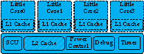
一、big-little的power架构
如下图,是big-little的power 架构,整个cluster的所有组件,均使用相同的电压域。用虚线框包围的区域,表示该模块,有单独的power domain。

二、DynamlQ的power架构
arm在推出DynamlQ架构之后,也推出了新的power架构,不然,无法精细化的控制power。如下图所示:

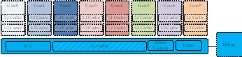
不同的颜色,表示不同的电压域,用虚线框包围的,表示该模块,有单独的power domain。
可以看出,采用DynamlQ架构之后,每个core,有自己的电压域。
相比之前的big-little架构,取消了,很多信号。

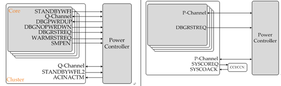
左边,是big-little架构下,core与power controller(以下简称PMU)的信号连接:
|
信号 |
说明 |
|
STANDBYWFI |
core是否进入wfi状态 |
|
Q_Channel |
Q-channel通道,用于控制core的power |
|
DBGPWRDUP |
debugger的core上电请求 |
|
DBGNOPWDRDWN |
debugger强制片内PMU,不允许对core下电的请求 |
|
WARMRSTREQ |
core的warm reset请求 |
|
SMPEN |
core的snoop使能请求 |
而cluster,与PMU的信号连接如下:
|
信号 |
说明 |
|
Q-Channel |
Q-Channel通道,用于控制cluster的power |
|
STANDYWFIL2 |
cluster是否处于wfi状态 |
|
ACINACTM |
右边,是DynamlQ架构下,core与pmu的信号连接:
|
信号 |
说明 |
|
P-Channel |
P-channel通道,用于控制core的power |
|
DBGRSTREQ |
core的warm reset请求 |
而cluster与pmu的信号连接如下:
|
信号 |
说明 |
|
P-Channel |
P-channel通道,用于控制cluster的power |
|
SYSCOREQ |
cluster coherency请求 |
|
SYSCOACK |
CCI/CCN总线矩阵的coherency响应 |
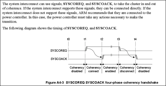
关于SYSCOREQ和SYSCOACK的解释如下:

三、P-Channel
P-channel的详细解析,可以看我之前写的博文:http://www.lujun.org.cn/?p=3634
对于P-Channel,有以下的一些信号:
|
Signal |
Description |
|
PREQ |
Power transition request. |
|
PSTATE |
Power transition state. PSTATE[3:0] is for power mode, and PSTATE[7:4] is for operating mode. |
|
PACTIVE |
The minimum power transition state requirement. The highest set HIGH bit indicates the required minimum power requirement separately for power mode and operating mode. This can be hint for power controller. PACTIVE[15:0] is for power mode, and PACTIVE[31:16] is for operating mode. |
|
PACCEPT |
Power transition request is accepted. |
|
PDENY |
Power transition request is denied. |
PMU就是通过P-Channel,来和core以及cluster来通信,实现power的控制。
四、power mode
power mode,表示硬件power的状态,分为core的power mode和cluster的power mode。
1、core的power mode
power mode有以下一些模式:
|
Power Mode |
Description |
|
ON |
In this mode, the core is fully functional. |
|
FUNC_RET |
This is a retention mode for the Ad-SIMD/FP unit. It can be entered when there are no instructions in the pipeline or pending for this unit. This mode can be enabled or disabled by software. A timeout value for entry into this mode from the last SIMD/FP instruction execution can be programmed. |
|
FULL_RET |
This is a retention mode for the full core domain. It can be entered when the core is in WFI/WFE. This mode can be enabled or disabled, separately for WFE and WFI. Separate timeout values for entry into this mode from WFE and WFI entry can be programmed. Direct transitions between ON and FULL_RET are only allowed when:
|
|
OFF_EMU |
This mode allows functional emulation of power off, whilst still maintaining debug state and allowing debug access. |
|
OFF |
This mode allows the core to be powered off. This mode powers off the complete core power domain. Hardware flushing of the L1 and L2 caches when OFF or OFF_EMU should be added. |
|
DBG_RECOV |
This mode allows cache memory contents and RAS registers to be preserved over a reset for debug purposes. This mode can be used to assist debug of external watchdog-trigger reset events when the whole system hangs. In this application, cluster power on reset or warm reset should be used together. |
可见,在DynamiQ架构下的power,core的power模式,有多种模式。定义这么多模式,也是为了能够精细化的控制。
PSTATE and PACTIVE 编码如下:
|
Power Mode |
PSTATE[3:0] |
PACTIVE[15:0] Related bit |
|
ON |
4'b1000 |
8 |
|
FUNC_RET |
4'b0111 |
7 |
|
FULL_RET |
4'b0101 |
5 |
|
OFF_EMU |
4'b0001 |
1 |
|
OFF |
4'b0000 |
0 (always tied to 1'b0) |
|
DBG_RECOV |
4'b1010 |
- |
比如,core要进入OFF状态,那么core会驱动P-Channel上的PACTIVE信号的0bit为1,PMU发现该bit为1,表示core要进入OFF状态。于是驱动PSTATE为4'b0000,并设置PREQ为1,发起power mode切换请求。core接收到该请求后,如果允许外部的PMU对core下电,会将PACCEPT信号拉高,PMU检测到该信号为高后,就可以将core断电了。
如果core不允许外部的PMU对core下电,会将PDENY信号拉高,PMU检测到该信号为高后,就知道不能对core断电。
2、cluster的power mode
cluster的power mode有如下4种:
|
Power Mode |
Description |
|
ON |
In this mode, the cluster is fully functional. |
|
FUNC_RET |
This is a retention mode for the L3 Cache RAM whilst the cluster is still functional. This mode can be enabled and disabled by software running on any of the cluster cores. A timeout value for entry into this mode from the last L3 cache access can be programmed. |
|
MEM_RET |
This mode allows the cluster logic to be off whilst retaining the L3 Cache RAM. This mode can be entered when the cluster is idle and all cores are OFF. |
|
OFF |
This mode allows the cluster to be powered off. This mode powers off the full cluster domain. Hardware flushing of the L3 Cache should be added when OFF is requested on the cluster P-Channel. |
PSTATE和PACTIVE编码:
|
Power Mode |
PSTATE[3:0] |
PACTIVE[15:0] Related bit |
|
ON |
4'b1000 |
8 |
|
FUNC_RET |
4'b0111 |
7 |
|
MEM_RET |
4'b0010 |
2 |
|
OFF |
4'b0000 |
0 (always tied to 1'b0) |
|
DBG_RECOV |
4'b1010 |
- |
比如,cluster要进入OFF状态,那么core会驱动P-Channel上的PACTIVE信号的0bit为1,PMU发现该bit为1,表示cluster要进入OFF状态。于是驱动PSTATE为4'b0000,并设置PREQ为1,发起power mode切换请求。cluster接收到该请求后,如果允许外部的PMU对core下电,会将PACCEPT信号拉高,PMU检测到该信号为高后,就可以将cluster断电了。
如果cluster不允许外部的PMU对cluster下电,会将PDENY信号拉高,PMU检测到该信号为高后,就知道不能对cluster断电。
五、寄存器
为了支持DnyamlQ架构的power精细化控制,arm定义了一些系统寄存器,用来软件控制硬件的power mode。
寄存器分为,对core和cluster。
1、对core
CPUWRCTLR_EL1和 DBGPRCR_EL1,两个系统寄存器。
|
Registers |
Bit |
Name |
Description |
|
CPUPWRCTLR_EL1 |
[0] |
PWRDN_EN |
Power off enable bit. This is used by software when the core is ready to be inactive at the next entry to WFI. The SMPEN bit from previous generation processors is removed. |
|
[3:0] |
RESERVED |
||
|
[6:4] |
WFI_RET_CTRL |
System counter tick control. When in multi-thread processor, larger one will be selected for whole core retention control. |
|
|
[9:7] |
WFE_RET_CTRL |
System counter tick control. When in multi-thread processor, larger one will be selected for whole core retention control. |
|
|
[12:10] |
SIMD_RET_CTRL |
System counter tick control. When in multi-thread processor, larger one will be selected for whole core retention control. |
|
|
[31:13] |
RESERVED |
||
|
DBGPRCR_EL1 |
[0] |
CORENPDRQ |
Request emulate power down if the system will power down the core. In multi-thread processor, if one thread has set this bit, the "no power down" request will be active. |
软件如果写bit0为1,表示要将core下电。当后续的程序执行wfi指令之后,core就会通过P-Channel的pactive,向PMU,发送off请求。
2、对cluster
cluster有以下寄存器:
-
cluster-down寄存器,控制power off和memory retention
-
power 控制寄存器:控制function retention,L3 cache RAM size
-
performance monitor:控制cache部分power off
|
Registers |
Bit |
Name |
Description |
|
CLUSTERPWRDN_EL1 (banked per-thread per- core) |
[0] |
Cluster power required |
Cluster power down request. If a thread sets its bit to 1'b1, it request that the cluster remains ON when all cores are off. If a thread sets to 1'b0, it requests that the cluster goes to OFF when all cores are off. If any of the banked cluster power requests is set to 1'b1, the cluster will remain ON when all cores are off. If all of the banked cluster power requests are set to 1'b0, the cluster will go to OFF when all cores are off. |
|
[1] |
Memory retention required |
Memory retention enable bit. If a thread sets its bit to 1'b1, it request that the cluster goes to MEM_RET when all cores are off. If a thread sets to 1'b0, it requests that the cluster goes to OFF when all cores are off. If any of the banked cluster power requests is set to 1'b1, the cluster will go to MEM_RET when all cores are off. If all of the banked cluster power requests are set to 1'b0, the cluster will go to OFF when all cores are off. |
|
|
[31:2] |
RAZ |
||
|
CLUSTERPWRCTLR_EL1 |
[2:0] |
L3 Cache Ram Retention Control |
System counter tick control. |
|
[3] |
RAZ |
||
|
[7:4] |
Cache Portion Power Request |
These bits are output on CLUSTERPACTIVE[19:16] to indicate to the power controller which cache portions must be powered. |
|
|
[31:8] |
RAZ |
||
|
CLUSTERL3HIT_EL1 |
[31:0] |
L3 Cache hit count |
Count of number of L3 Cache hit. |
|
CLUSTERL3MISS_EL1 |
[31:0] |
L3 Cache miss count |
Count of number of L3 Cache misses. |
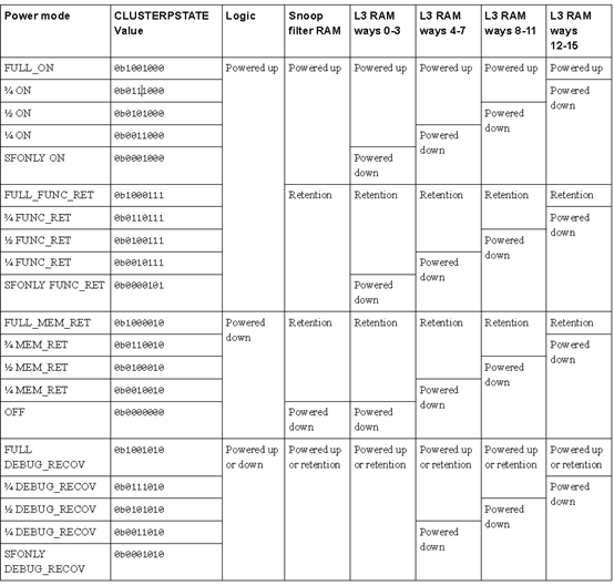
六、cache的power
DynamlQ架构的cache的power mode,是多种组合。如下图:

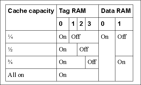
就是看tag ram和data ram的上电状态。至于为什么cache,会有这么多种power mode,是因为DynamlQ架构下,cache变大很大。L2 cache成每个core私有的,并且还增加了L3 cache。如果不对cache的power,做精细化的管理,那么功耗,也就上去了。
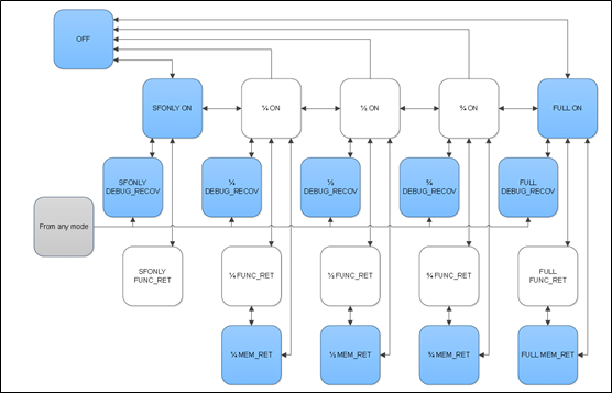
下图是power mode的转换图:

以下是power mode的编码:

七、总结
为了适应复杂的DynamIQ架构,arm将power的架构也做了很大的修改。其中一点,是引入了P-Channel,实现更负责的power状态控制。以及对硬件,定义了很多的power mode,用于软件来方便的控制,从而实现低功耗。