基于Three.js的大屏3D地图(一)——地图模型渲染
依赖安装
yarn add three
yarn add @types/three
yarn add d3-geo
three库安装后在node_modules下其还包含核心three/src和插件three/example/jsm的源码,在开发调试时可以直接查阅。使用Three.js过程中会涉及到许多的类、方法及参数配置,所以建议安装@types/three库;不仅能提供类型提示,还有助于加快理解Three.js中的众多概念及关联关系。
d3-geo是d3库中独立出来专门用于处理地理数据可视化的模块。我们需要使用d3-geo中的部分方法来对原始的经纬度数据做墨卡托投影以在二维平面上正确定位。
数据处理
GeoJSON数据
我们是通过GeoJSON数据格式来绘制地图的。在开发测试阶段可以直接从阿里云的DataV地理工具中在线获取地图数据。
获取到的GeoJSON格式框架如下:
{
  "type": "FeatureCollection",
  "features": [
    {
      "type": "Feature",
      "properties": {
        "adcode": 110000,
        "name": "北京市",
        "center": [116.405285, 39.904989],
        "centroid": [116.41995, 40.18994]
      },
      "geometry": {
        "type": "MultiPolygon",
        "coordinates": [[[[]]]]
      }
    }
  ]
}
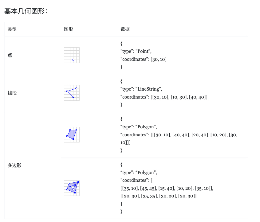
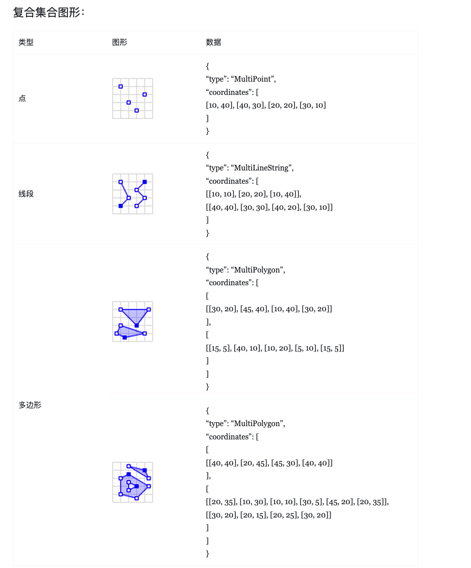
我们处理地图数据需要考虑的是MultiPolygon和Polygon类型。
墨卡托投影
经纬度坐标是记录某点在地球表面这一“曲面”结构上的确切位置,如果我们直接使用这些点坐标在二维平面上绘制是会产生形变的,因而需要先对所有的坐标做一次墨卡托投影转换以使它们能够在同一平面上展示。
在渲染地图前还要确保地图位于场景的中心,因此需要先计算出当前地图数据的中心点,将该中心点作为投影中心:
/**
 * 计算边界和中心位置
 */
calcSide(geojson: any) {
    const mapSideInfo = this.mapSideInfo = { minLon: Infinity, maxLon: -Infinity, minLat: Infinity, maxLat: -Infinity }
    const { features } = geojson
    features.forEach(feature => {
        const { coordinates, type } = feature.geometry

        coordinates.forEach(coordinate => {
            if(type === "MultiPolygon") coordinate.forEach(item => dealWithCoord(item))
            if(type === "Polygon") dealWithCoord(coordinate)
        })
    })

    this.centerPos = {
        x: (mapSideInfo.maxLon + mapSideInfo.minLon) / 2,
        y: (mapSideInfo.maxLat + mapSideInfo.minLat) / 2
    }


    function dealWithCoord(lonlatArr) {
        lonlatArr.forEach(([lon, lat]) => {
            if(lon > mapSideInfo.maxLon) mapSideInfo.maxLon = lon
            if(lon < mapSideInfo.minLon) mapSideInfo.minLon = lon
            if(lat > mapSideInfo.maxLat) mapSideInfo.maxLat = lat
            if(lat < mapSideInfo.minLat) mapSideInfo.minLat = lat
        })
    }
}
得出中心位置后,调用d3-geo的geoMercator生成转换方法:
this.coordTrans = geoMercator().center([this.centerPos.x, this.centerPos.y]).translate([0, 0])
将中心点坐标作为参数传入center()后返回一个变更了投影中心的新方法。接着我们还需要调用translate来修改默认的偏移量(见文档:https://d3js.org/d3-geo/projection#projection_translate )
绘制地图
基础场景搭建
init(initData: confData) {
    const { width, height, container } = initData
    this.cfg = initData

    // 创建场景与透视相机
    const scene = new THREE.Scene()
    this.scene = scene
    const camera = new THREE.PerspectiveCamera(45, width / height, 0.1, 1000)
    camera.position.set(0, 0, 200)
    this.camera = camera
    // Webgl渲染器
    const renderer = new THREE.WebGLRenderer()
    renderer.setSize(width, height)
    this.renderer = renderer
    // 轨道控制器
    new OrbitControls(camera, renderer.domElement)

    container.appendChild(renderer.domElement)

    // 2D渲染器
    const labelRenderer = new CSS2DRenderer()
    labelRenderer.domElement.style.position = "absolute"
    labelRenderer.domElement.style.top = "0px"
    labelRenderer.domElement.style.pointerEvents = "none"
    labelRenderer.setSize(width, height)
    container.appendChild(labelRenderer.domElement)
    this.css2DRenderer = labelRenderer

    // 开启循环渲染帧
    const animate = () => {
        renderer.render(scene, camera)
        labelRenderer.render(scene, camera)

        this.requestID = requestAnimationFrame(animate)
    }
    animate()
}
在开发阶段还可以引入坐标轴和性能检测面板来辅助开发:
// 坐标轴参考
this.axesHelper = new THREE.AxesHelper(150)
this.scene.add(this.axesHelper)
// 性能监测
this.stats = new Stats()
this.cfg.container.appendChild(this.stats.dom)

const animate = () => {
    // ...
    this.stats?.update()
}
绘制平面地图
首先利用THREE.Shape对象根据GeoJSON中的所有点连接成线,构造出地图在平面的轮廓:
createMapModel(geojson) {
    features.forEach(feature => {
        const { coordinates, type } = feature.geometry

        coordinates.forEach(coordinate => {
            if(type === "MultiPolygon") coordinate.forEach(item => dealWithCoord(item))
            if(type === "Polygon") dealWithCoord(coordinate)
        })
    })

    function dealWithCoord(lonlatArr) {
        const pieceMesh = _this.createPieceMesh(lonlatArr)
        _this.scene.add(pieceMesh)
    }
}

createPieceMesh(lonlatArr) {
    // 绘制区块形状
    const shape = new THREE.Shape()
    lonlatArr.forEach((lonlat, index) => {
        let [x, y] = this.coordTrans(lonlat)
        y = -y

        if(!index) shape.moveTo(x, y)
        else shape.lineTo(x, y)
    })

    // todo
}
THREE.ExtrudeGeometry挤出三维效果
有用过Blender或3DMax之类三维设计软件的同学应该对Extrude挤出操作不陌生,该操作就是将模型上的某一个平面沿着其法线方向拉伸出来。ThreeJS中有一个ExtrudeGeometry方法可以达到同样的目的。我们直接用下面的动图来生动展示下是如何从二维平面上挤出3D地图的:
createPieceMesh(lonlatArr: number[][]): THREE.Mesh {
    // 绘制区块形状
    // ...

    // 构造几何体
    const geometry = new THREE.ExtrudeGeometry(shape, {
        depth: this.cfg.depth,
        bevelEnabled: false
    })

    const material = new THREE.MeshBasicMaterial({ color: 0xffffff })
    const mesh = new THREE.Mesh(geometry, material)
    return mesh
}

描边
上一步渲染的模型是纯白色材质的,为了方面观察还加上了黑色描边,下面补上代码:
createLine(lonlatArr: number[][]) {
    const points: number[] = []
    lonlatArr.forEach(lonlat => {
        let [x, y] = this.coordTrans(lonlat)
        y = -y
        points.push(x, y, 0)
    })

    const lineGeometry = new THREE.BufferGeometry().setFromPoints(points)
    const meterial = new THREE.LineBasicMaterial({ color: 0x000000, linewidth: 2 })

    const line = new THREE.Line(lineGeometry, meterial)
    return line
}
线宽问题
线条材质的参数中有一个linewidth,可以供我们配置线条的宽度。但在实际使用中发现线宽只能固定为1不变,官方文档中给出了如下解释:

同时也给出了解决方案,可以使用拓展包中的Line2来渲染不同宽度的线条:
import { Line2 } from 'three/examples/jsm/lines/Line2'
import { LineGeometry } from 'three/examples/jsm/lines/LineGeometry'
import { LineMaterial } from 'three/examples/jsm/lines/LineMaterial'

createLine(lonlatArr: number[][]) {
    const points: number[] = []
    lonlatArr.forEach(lonlat => {
        let [x, y] = this.coordTrans(lonlat)
        y = -y
        points.push(x, y, 0)
    })

    const lineGeometry = new LineGeometry()
    lineGeometry.setPositions(points)

    const lineMaterial = new LineMaterial({ color: 0x000000, linewidth: 2 })
    const line = new Line2(lineGeometry, lineMaterial)
    line.position.z = this.cfg.depth + 0.01

    return line
}
LineGeometry缺陷
在构造LineGeometry时需要注意使用的是setPositions方法而不是setFromPoints。在three.js的171版本之前是不能使用setFromPoints方法来构造geometry的。
const points: THREE.Vector3[] = []
lonlatArr.forEach(lonlat => {
    let [x, y] = this.coordTrans(lonlat)
    y = -y
    points.push(new THREE.Vector3(x, y, 0))
})

// Error:
const lineGeometry = new LineGeometry()
lineGeometry.setFromPoints(points)

因为LineGeometry是继承自LineSegmentsGeometry,但该类在实例化中会有预设的position属性,从而导致执行setFromPoints时发生数组下标越界的问题:https://github.com/mrdoob/three.js/commit/add7f9ba79a7f23732cf6e9e25ebcd4987550d45。
为地图正面和侧面应用不同的样式
目前为止我们的地图有一种样式,整个模型表面都是白色的。
const material = new THREE.MeshBasicMaterial({ color: 0xffffff })	// 纯白色材质
const mesh = new THREE.Mesh(geometry, material)
我们的大屏3D地图需要更为多样的表现,能对模型正面侧面应用上不同的样式。官方文档在ExtrudeGeometry构造函数的下面有这么一段说明:
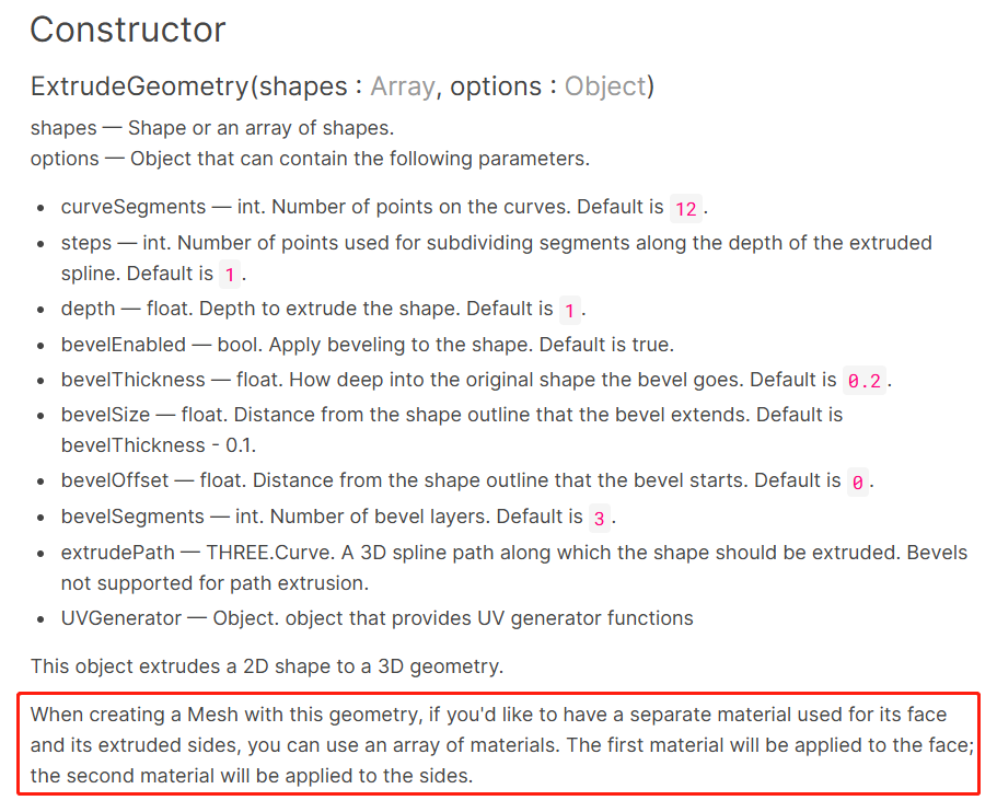
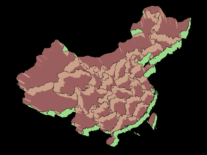
在构造Mesh对象的第二个参数中传入材质数组的话,则可以将不同材质分别应用到模型的正面和侧面。我们用一个泥红色的半透明材质用作正面材质,草绿色材质用于侧面,渲染出一副水彩风格的地图:
const material = new THREE.MeshBasicMaterial({
    color: 0xdd8787,
    transparent: true,	// 开启透明度
    opacity: 0.7
})
const materialSide = new THREE.MeshBasicMaterial({
    color: 0x9bda8c
})

// ...

const mesh = new THREE.Mesh(geometry, [material, materialSide])
纹理贴图
创建材质Material的时候除了可以通过color字段配置颜色,还可以通过map字段传入Texture对象来为模型贴上贴图。
const material = new THREE.MeshBasicMaterial({
    map: new THREE.TextureLoader().load('./top_image.jpg')
})
const materialSide = new THREE.MeshBasicMaterial({
    map: new THREE.TextureLoader().load('./side_image.jpg')
})

// ...

const mesh = new THREE.Mesh(geometry, [material, materialSide])
读者可以用任意图片用作贴图看下渲染的效果,会发现贴图以一种非常奇怪的方式拉伸。这是因为我们没有定义好模型的UV映射坐标,即geometry.attributes.uv;该属性定义了应该如何将纹理贴图上的像素应用在我们的模型表面。
为了方便讲解,笔者这里不使用地图数据构造的geometry,而是一个相对更加简单的几何体:
const shape = new THREE.Shape()
shape.moveTo(-4, 4)
shape.lineTo(-4, -4)
shape.lineTo(4, -4)
shape.lineTo(4, 1)
shape.lineTo(1, 1)
shape.lineTo(1, 4)

const shape2 = new THREE.Shape()
shape2.moveTo(3, 4)
shape2.lineTo(4, 4)
shape2.lineTo(4, 3)
shape2.lineTo(3, 3)

const m1 = new THREE.MeshLambertMaterial({ color: 0xF0B5B5 }), m2 = new THREE.MeshLambertMaterial({ color: 0xffffff })
const geometry = new THREE.ExtrudeGeometry(shape, { depth: this.cfg.depth, bevelEnabled: false })
const geometry2 = new THREE.ExtrudeGeometry(shape2, { depth: this.cfg.depth, bevelEnabled: false })
const mesh = new THREE.Mesh(geometry, [m1, m2])
const mesh2 = new THREE.Mesh(geometry2, [m1, m2])
this.scene.add(mesh, mesh2)
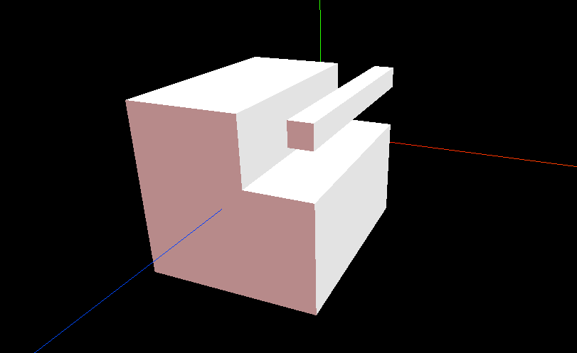
接着为这两个几何体应用下面的UV测试图片作为纹理贴图:

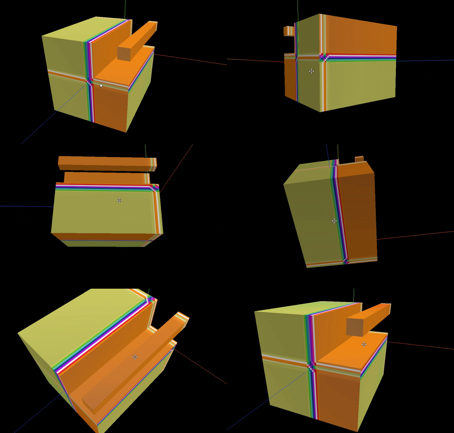
可以看到我们的UV测试图只以1X1单位大小显示在模型表面上的一小部分地方,其他部分则由图片的四边拉伸填充至整个表面。而另外还有某些面连贴图都无法完整显示。
将几何体的position及uv属性打印出来:
console.log(mesh.geometry.getAttribute('position'))
console.log(mesh.geometry.getAttribute('uv'))


可以看到uv值并不都在[0-1]的区间内。对于uv值小于0的区域,会直接从贴图u/v坐标=0处采样像素点填充;同理,大于1的区域则是从u/v坐标=1处采样。这也就是上一步中贴图被异常拉伸的原因。
那么,打印的这些uv属性是如何得来的呢?我们看回文档ExtrudeGeometry的构造函数中有一个UVGenerator选项:

通过ExtrudeGeometry对象生成几何体时可以传入UVGenerator函数来决定几何体的uv应该如何计算。但文档中并没有进一步介绍该函数如何使用,需要直接看源码才能知道细节。打开ExtrudeGeometry的源码处,在构造函数中有这么一行对uv生成函数的处理逻辑[constructor -> addShape]:
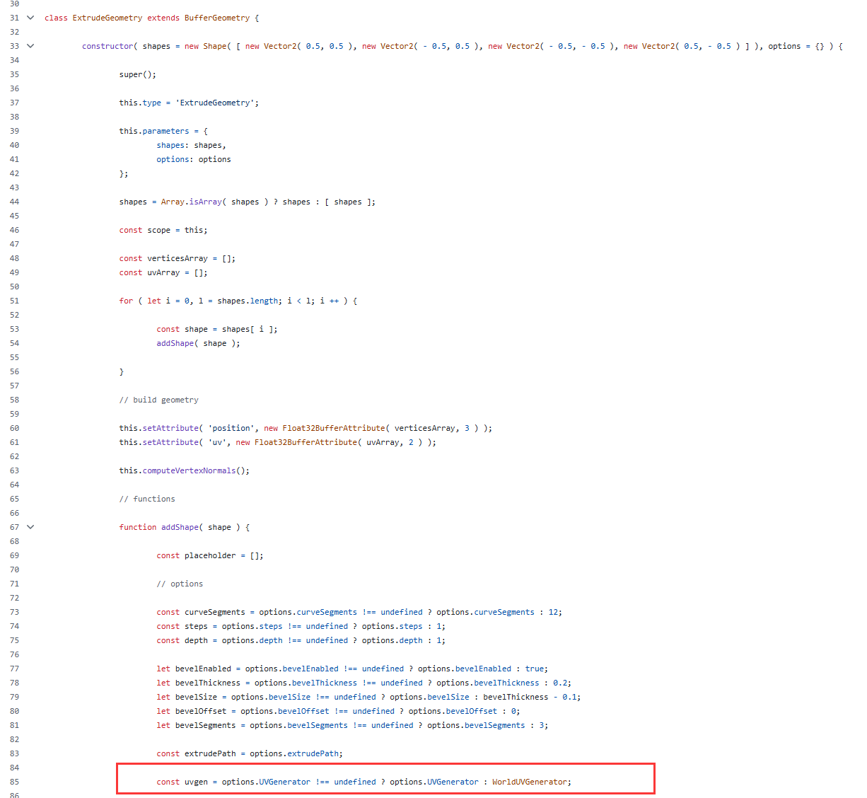
在外部没有传入UVGenerator的情况下则会使用内置的WorldUVGenerator 。在WorldUVGenerator中有generateTopUV和generateSideWallUV两个函数分别用于定义顶面和侧面的uv生成逻辑:
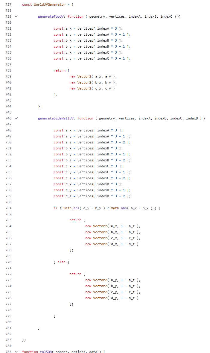
结合命名和代码大致逻辑很容易看出来,默认的生成规则其实就是根据世界坐标的x/y/z值来作为uv值。顶面的生成规则很简单,直接使用顶点的xy坐标值用作uv值。侧面的生成规则相对复杂些,需要考虑前两个顶点的x/y值的差异量来判断是x·z平面来用作贴图还是y·z平面。
侧面纹理
既然可以自定义UV生成规则,就好解决了。我们先从generateSideWallUV开始。对于ExtrudeGeometry中的每一个侧面矩形,都会调用一次generateSideWallUV,传入的四个顶点下标index顺序是固定的:从该侧边平面的法线方向观察(即我们Extrude出来的几何体面向摄像机的一面,另一面默认是不可见的),垂直于shape平面的边作为底边来看的话,读取顺序是从左下角逆时针开始。
明白了上述原理后,结合笔者的需求:对于上传的侧面贴图,应用到每一个侧面并将其撑满。修改后的generateSideWallUV代码就很简单了:
generateSideWallUV: function(geometry, vertices, indexA, indexB, indexC, indexD) {
    return [
        new Vector2(0, 0),
        new Vector2(1, 0),
        new Vector2(1, 1),
        new Vector2(0, 1)
    ]
}

顶面纹理
顶面的贴图需求和侧面类似,也是期望贴图能够撑满该面。有所不同的是顶面不是像侧面那样的矩形,而是一个不规则形状。需要知道顶面的“包围矩形”,然后让贴图撑满该矩形,就能达到我们的目的。
在ThreeJS中有一个Box3类可以帮助我们计算场景中物体的包围盒:
const box = new THREE.Box3()
box.setFromObject(this.scene)
const size = new THREE.Vector3()
box.getSize(size)

console.log('box: ', box)
console.log('size: ', size)
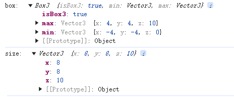
有了包围盒信息后就可以计算顶面中每个顶点所对应的UV值了。但是笔者这里不打算调整默认的generateTopUV;相较于在每次调用的generateTopUV中做计算,我们可以在创建纹理的时候就配置好它的缩放及偏移量:
const texture = new THREE.TextureLoader().load('./uv_test.jpg')
texture.colorSpace = THREE.SRGBColorSpace

const box = new THREE.Box3()
box.setFromObject(this.mapPieceGroup)
const size = new THREE.Vector3()
box.getSize(size)

texture.repeat.set(1 / size.x, 1 / size.y)
texture.offset.set(Math.abs(box.min.x / size.x), Math.abs(box.min.y / size.y))
texture.repeat的传参可以是小于1的值,相当于将贴图放大了。传入1 / size.x, 1 / size.y使得贴图的宽高同顶面的包围矩形一样。
接着设置纹理偏移texture.offset,使得缩放后的贴图和包围矩形对齐。
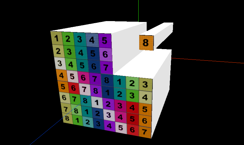
至此,纹理贴图也大功告成。让我们回到3D地图配置,整合本文的所有代码,根据设计图和相应的素材,检验下我们的demo成果:
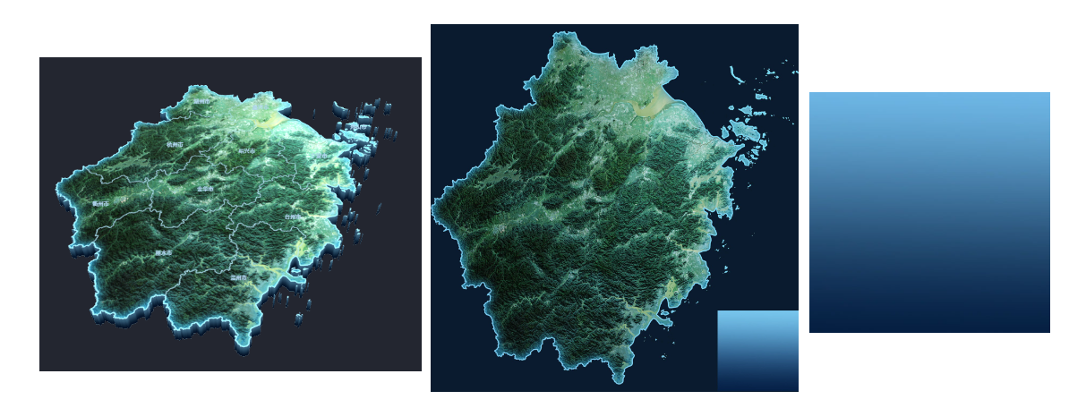
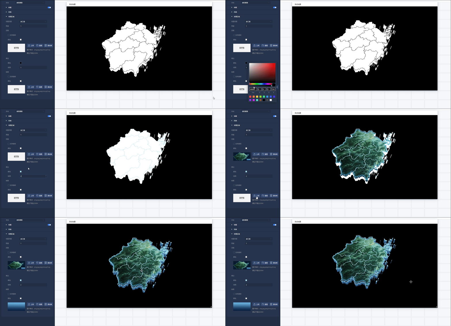


【推荐】国内首个AI IDE,深度理解中文开发场景,立即下载体验Trae
【推荐】编程新体验,更懂你的AI,立即体验豆包MarsCode编程助手
【推荐】抖音旗下AI助手豆包,你的智能百科全书,全免费不限次数
【推荐】轻量又高性能的 SSH 工具 IShell:AI 加持,快人一步