
ABB AC 900F学习笔记65:Freelance_Mounting_and_Installation_AC_900F_Controller-25
5.3 Coupler bus slots
耦合器总线插槽
The C1 to C2 coupler bus slots serve for connecting the CI/CM communication interfaces to the CPU module. When configuring the AC 900F controller and integrating a CI/CM module, the bottom module part must be plugged in first. Then press the top module part backwards until it locks in place at the top of the slot. To check whether the module is securely locked, try to pull it out after it is locked
C1 到 C2 耦合器总线插槽用于连接到CPU 模块的CI/CM通信接口。当配置AC 900F控制器和集成CI/CM模板时,必须先插入底板。然后向后模块顶部部分,直到它在插槽顶部锁住。为检查是否锁住,可以尝试在锁住后拔出(看是否能拔出来)
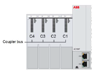
A TA dummy coupler is installed and removed from the C1 to C4 slots as described for a communication interface
按照通讯接口的(安装和拆除)描述,安装和拆除空插槽保护盖板。
The module change during operation is described in Section 8, Service
在线模块更改(方法)在第八章有描述。
5.4 PM housing front
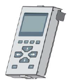
The central area of the housing front of the CPU module is equipped with a removable cover. This cover can be taken off without any tools and be replaced by a TD display unit.
CPU模板前面中央区域配置可拆除的盖子。取掉此盖板无需任何工具,并用TD显示单元替代。
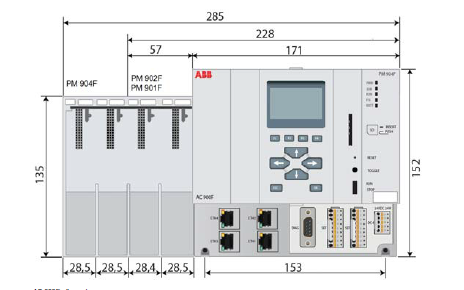
5.5 Dimensional drawings
图纸尺寸
Note: All dimensions are indicated in mm.
注意:所有的尺寸单位是毫米
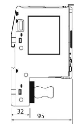
5.5.1 Dimensional drawings of the PM CPU module
CPU模板的图纸尺寸
Front view
前视图
Lateral view
侧视图

 浙公网安备 33010602011771号