【ESP32 Arduino】RS485通信及MODBUS RTU通信实例
1、研究官方例子
在Arduino IDE 2.3.2中,示例代码路径
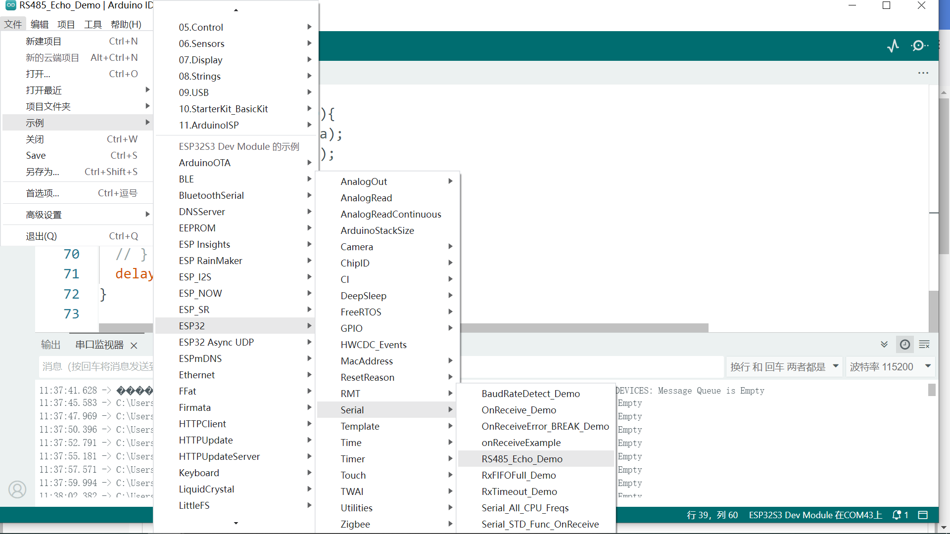
注意代码注释中链接:https://docs.espressif.com/projects/esp-idf/en/latest/esp32/api-reference/peripherals/uart.html#circuit-a-collision-detection-circuit
2、示例代码修改与测试
因使用RS485调制解调模块的接口引脚同常规芯片的DE和/RE逻辑相反。故调用ESP更底层C语言API函数解决。
具体为:半双工,使用RTS信号控制RS485调制解调模块的数据方向,函数为: uart_set_line_inverse(1, UART_SIGNAL_RTS_INV);
/*
  This Sketch demonstrates how to use the Hardware Serial peripheral to communicate over an RS485 bus.

  Data received on the primary serial port is relayed to the bus acting as an RS485 interface and vice versa.

  UART to RS485 translation hardware (e.g., MAX485, MAX33046E, ADM483) is assumed to be configured in half-duplex
  mode with collision detection as described in
  https://docs.espressif.com/projects/esp-idf/en/latest/esp32/api-reference/peripherals/uart.html#circuit-a-collision-detection-circuit

  To use the script open the Arduino serial monitor (or alternative serial monitor on the Arduino port). Then,
  using an RS485 tranciver, connect another serial monitor to the RS485 port. Entering data on one terminal
  should be displayed on the other terminal.
*/
#include "hal/uart_types.h"
#include "driver/uart.h"
#include "driver/gpio.h"

#define RS485_RX_PIN 5
#define RS485_TX_PIN 4
#define RS485_RTS_PIN 6

#define RS485 Serial1

void setup() {
  Serial.begin(115200);
  while (!Serial) {
    delay(10);
  }

  RS485.begin(9600, SERIAL_8N1, RS485_RX_PIN, RS485_TX_PIN);
  while (!RS485) {
    delay(10);
  }
  if (!RS485.setPins(-1, -1, -1, RS485_RTS_PIN)) {  // -1 保持引脚不变
    Serial.print("Failed to set RS485 pins");
  }

  //esp_err_t uart_set_line_inverse(uart_port_t uart_num, uint32_t inverse_mask)
  uart_set_line_inverse(1, UART_SIGNAL_RTS_INV);  // 特殊,修改输出或输入的通信电信号正负逻辑

  // Certain versions of Arduino core don't define MODE_RS485_HALF_DUPLEX and so fail to compile.
  // By using UART_MODE_RS485_HALF_DUPLEX defined in hal/uart_types.h we work around this problem.
  // If using a newer IDF and Arduino core you can omit including hal/uart_types.h and use MODE_RS485_HALF_DUPLEX
  // defined in esp32-hal-uart.h (included during other build steps) instead.
  if (!RS485.setMode(UART_MODE_RS485_HALF_DUPLEX)) {
    Serial.print("Failed to set RS485 mode");
  }
}

void loop() {
  // Serial.println("loop:");
  // RS485.write("1234567890");
  String serial_data=""; /* 存放接收到的串口数据 */
  if (RS485.available()) {


    int c = RS485.read(); /* 读取一字节串口数据 */
    while (c >= 0) {
      serial_data += (char)c; /* 存放到serial_data变量中 */
      c = RS485.read();       /* 继续读取一字节串口数据 */
    }
  }
  if(serial_data.length()>0){
  Serial.println(serial_data);
  RS485.println(serial_data);
  serial_data ="";
  }
  // if (Serial.available()) {
  //   RS485.write(Serial.read());
  // }
  delay(100);
}
3、查找的MODBUS参考帖子,确定第三方库eModbus并下载安装
ESP32 使用RS485模块实现Modbus通信(eModbus)
https://mp.weixin.qq.com/s/3mT605kXvFT2JCfg6plYLg?poc_token=HEOUmGajTehMUKHW-FPlFNsfnvrrBHeqGKYBbBht
下载安装eModbus库(https://github.com/eModbus/eModbus)。并需要添加AsyncTCP库( https://github.com/dvarrel/AsyncTCP)
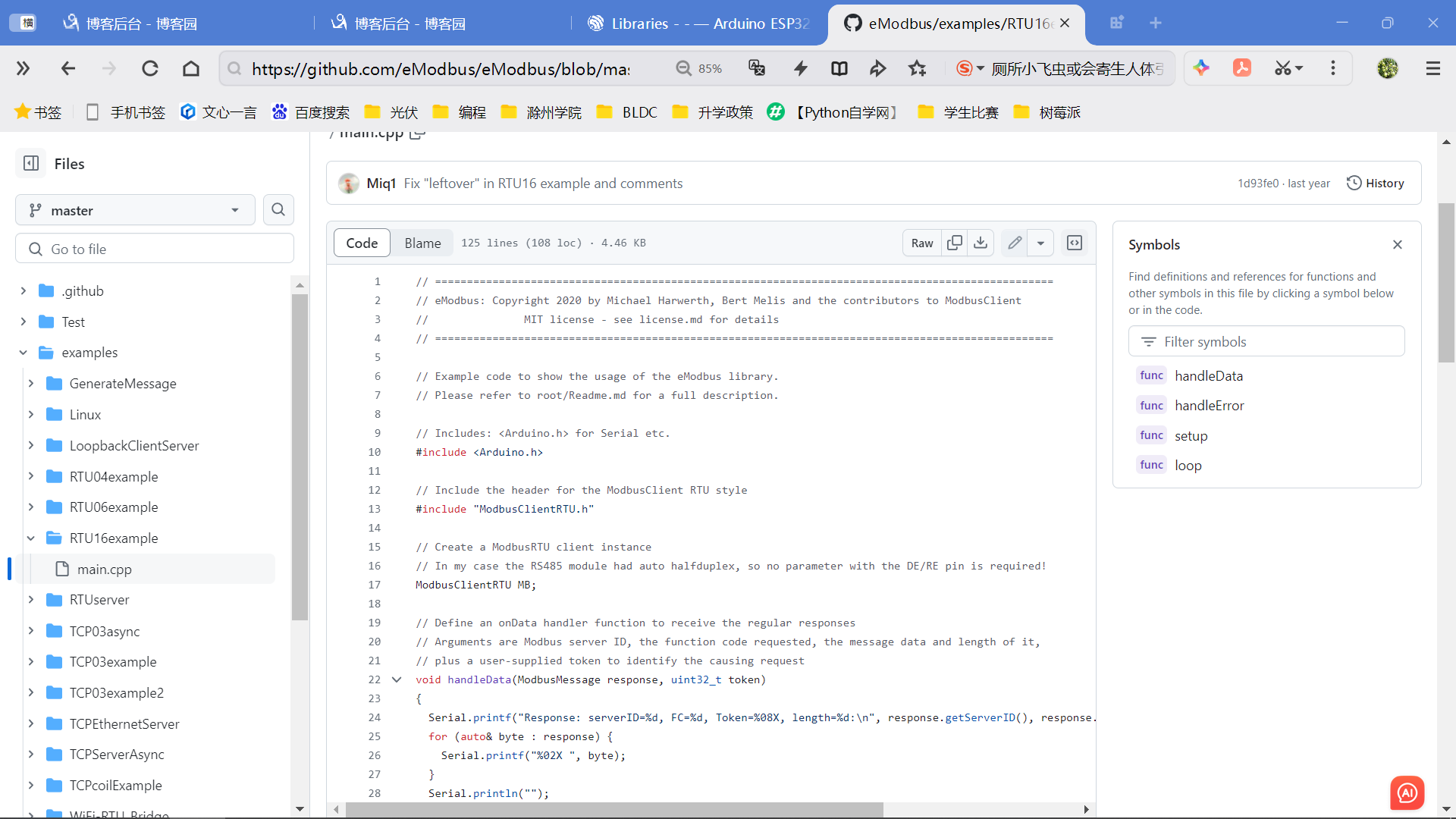
在https://github.com/eModbus/eModbus研究示例代码,也可以在安装的库文件夹中查找代码,并登录相关网页学习。
这里复制RTU16example的main.c文件代码,编译成功,代码初步可用。这也说明安装的库eModbus可以使用。
根据引脚连接关系,定义RX, TX, RTS(视RS485调制解调模块选用)。
其他参考资料:https://getiot.tech/modbus
4、具体示例
使用RTS,使用RS485调制解调模块的接口引脚同常规芯片的DE和/RE逻辑相反。
修改上述示例代码,经调试通过如下:
// =================================================================================================
// eModbus: Copyright 2020 by Michael Harwerth, Bert Melis and the contributors to ModbusClient
//               MIT license - see license.md for details
// =================================================================================================

// Example code to show the usage of the eModbus library.
// Please refer to root/Readme.md for a full description.

// Includes: <Arduino.h> for Serial etc.
#include <Arduino.h>

// Include the header for the ModbusClient RTU style
#include "ModbusClientRTU.h"

//增添头文件
#include "hal/uart_types.h"
#include "driver/uart.h"
#include "driver/gpio.h"
//增添宏定义 与RS485调制解调模块接口
#define RS485_RX_PIN 5
#define RS485_TX_PIN 4
#define RS485_RTS_PIN 6
#define RS485 Serial1
#define RS485_SerialNum 1
// Create a ModbusRTU client instance
// In my case the RS485 module had auto halfduplex, so no parameter with the DE/RE pin is required!
ModbusClientRTU MB;

// Define an onData handler function to receive the regular responses
// Arguments are Modbus server ID, the function code requested, the message data and length of it,
// plus a user-supplied token to identify the causing request
void handleData(ModbusMessage response, uint32_t token) {  // 回调函数
  Serial.printf("Response: serverID=%d, FC=%d, Token=%08X, length=%d:\n", response.getServerID(), response.getFunctionCode(), token, response.size());
  for (auto &byte : response) {
    Serial.printf("%02X ", byte);
  }
  Serial.println("");
}

// Define an onError handler function to receive error responses
// Arguments are the error code returned and a user-supplied token to identify the causing request
void handleError(Error error, uint32_t token) {  // 回调函数
  // ModbusError wraps the error code and provides a readable error message for it
  ModbusError me(error);
  Serial.printf("Error response: %02X - %s\n", (int)me, (const char *)me);
}

// Setup() - initialization happens here
void setup() {
  // Init Serial monitor
  Serial.begin(115200);
  while (!Serial) {}
  Serial.println("__ OK __");

  // Set up Serial2 connected to Modbus RTU
  // (Fill in your data here!)
  // RTUutils::prepareHardwareSerial(Serial2);
  // Serial2.begin(19200, SERIAL_8N1, GPIO_NUM_17, GPIO_NUM_16);

  // RS485串口外设 连接 Modbus RTU
  RTUutils::prepareHardwareSerial(RS485);
  RS485.begin(9600, SERIAL_8N1, RS485_RX_PIN, RS485_TX_PIN);
  while (!RS485) {
    delay(10);
  }
  if (!RS485.setPins(-1, -1, -1, RS485_RTS_PIN)) {  // -1 保持引脚不变
    Serial.print("Failed to set RS485 pins");
  }
  // //esp_err_t uart_set_line_inverse(uart_port_t uart_num, uint32_t inverse_mask)
  uart_set_line_inverse(RS485_SerialNum, UART_SIGNAL_RTS_INV);  // 特殊,修改输出或输入的通信电信号正负逻辑
  // Certain versions of Arduino core don't define MODE_RS485_HALF_DUPLEX and so fail to compile.
  // By using UART_MODE_RS485_HALF_DUPLEX defined in hal/uart_types.h we work around this problem.
  // If using a newer IDF and Arduino core you can omit including hal/uart_types.h and use MODE_RS485_HALF_DUPLEX
  // defined in esp32-hal-uart.h (included during other build steps) instead.
  if (!RS485.setMode(UART_MODE_RS485_HALF_DUPLEX)) {
    Serial.print("Failed to set RS485 mode");
  }
  // END,RS485串口外设 连接 Modbus RTU

  // Set up ModbusRTU client.
  // - provide onData handler function
  MB.onDataHandler(&handleData);    // 回调函数
                                    // - provide onError handler function
  MB.onErrorHandler(&handleError);  // 回调函数
                                    // Set message timeout to 2000ms
  MB.setTimeout(2000);
  // Start ModbusRTU background task
  //MB.begin(Serial2);
  MB.begin(RS485);

  // We will first read the registers, then write to them and finally read them again to verify the change

  // Create request for
  // (Fill in your data here!)
  // - server ID = 1
  // - function code = 0x03 (read holding register)
  // - address to read = word 33
  // - data words to read = 6
  // - token to match the response with the request.
  //
  // If something is missing or wrong with the call parameters, we will immediately get an error code
  // and the request will not be issued
  uint32_t Token = 1111;

  Error err = MB.addRequest(Token++, 1, READ_HOLD_REGISTER, 33, 6);
  if (err != SUCCESS) {
    ModbusError e(err);
    Serial.printf("Error creating request: %02X - %s\n", (int)e, (const char *)e);
  }

  // Create request for
  // (Fill in your data here!)
  // - server ID = 1
  // - function code = 0x16 (write multiple registers)
  // - address to write = word 33ff
  // - data words to write = see below
  // - data bytes to write = see below
  // - token to match the response with the request.
  //
  uint16_t wData[] = { 0x1111, 0x2222, 0x3333, 0x4444, 0x5555, 0x6666 };

  err = MB.addRequest(Token++, 1, WRITE_MULT_REGISTERS, 33, 6, 12, wData);
  if (err != SUCCESS) {
    ModbusError e(err);
    Serial.printf("Error creating request: %02X - %s\n", (int)e, (const char *)e);
  }

  // Create request for
  // (Fill in your data here!)
  // - server ID = 1
  // - function code = 0x03 (read holding register)
  // - address to read = word 33
  // - data words to read = 6
  // - token to match the response with the request.
  //
  err = MB.addRequest(Token++, 1, READ_HOLD_REGISTER, 33, 6);
  if (err != SUCCESS) {
    ModbusError e(err);
    Serial.printf("Error creating request: %02X - %s\n", (int)e, (const char *)e);
  }

  // The output on the Serial Monitor will be (depending on your Modbus the data will be different):
  //      __ OK __
  //      Response: serverID=1, FC=3, Token=00000457, length=15:
  //      01 03 0C 60 61 62 63 64 65 66 67 68 69 6A 6B
  //      Response: serverID=1, FC=16, Token=00000458, length=19:
  //      01 10 00 21 00 06 0C 11 11 22 22 33 33 44 44 55 55 66 66
  //      Response: serverID=1, FC=3, Token=00000459, length=15:
  //      01 03 0C 11 11 22 22 33 33 44 44 55 55 66 66
}

// loop() - nothing done here today!
void loop() {
}
串口助手观察结果如下:
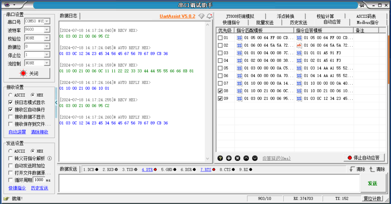
[2024-07-18 14:17:24.040]# RECV HEX>
01 03 00 21 00 06 95 C2

[2024-07-18 14:17:24.045]# AUTO REPLY HEX>
01 03 0C 12 34 23 45 34 56 45 67 56 78 67 89 CB 36

[2024-07-18 14:17:24.159]# RECV HEX>
01 10 00 21 00 06 0C 11 11 22 22 33 33 44 44 55 55 66 66 8B 81

[2024-07-18 14:17:24.164]# AUTO REPLY HEX>
01 10 00 21 00 06 10 01

[2024-07-18 14:17:24.255]# RECV HEX>
01 03 00 21 00 06 95 C2

[2024-07-18 14:17:24.260]# AUTO REPLY HEX>
01 03 0C 12 34 23 45 34 56 45 67 56 78 67 89 CB 36
5、收获
1、arduino有大量第三方库,有示例代码参考。轮子很多!
2 、arduino-esp32 是在C API基础上进一步的封装,所以可以直接调用更底层的API函数,例如:这里实现的RTS信号逻辑设置。
3 、arduino-esp32文档官网:https://docs.espressif.com/projects/arduino-esp32/en/latest/libraries.html?highlight=uart
6、补充 ESP32 作为 modbus-rtu的server@2025.1.24
1、EPS32作为 modbus-rtu的server,示范了 03 和 06 两个功能。
2、示范使用Free RTOS和其队列传数
3、LED PWM功能软件编译和运行可以,但是在电路上调试没通过。
因为没有调用编写的初始化函数,现在通过。
#include <dummy.h> // ================================================================================================= // eModbus: Copyright 2020 by Michael Harwerth, Bert Melis and the contributors to ModbusClient // MIT license - see license.md for details // ================================================================================================= // Example code to show the usage of the eModbus library. // Please refer to root/Readme.md for a full description. // Includes: <Arduino.h> for Serial etc. #include <Arduino.h> #include "HardwareSerial.h" // Modbus server include #include "ModbusServerRTU.h" //增添头文件 #include "hal/uart_types.h" #include "driver/uart.h" #include "driver/gpio.h" //#include "ledc.h" //#include "soc/soc_caps.h" //增添宏定义 与RS485调制解调模块接口 #define RS485_RX_PIN 16 #define RS485_TX_PIN 17 #define RS485_RTS_PIN 4 #define RS485 Serial1 #define RS485_SerialNum UART_NUM_1 // 定义队列,用来传输数据 QueueHandle_t queueMsg = xQueueCreate(8, sizeof(char[2])); ////实现PWM控制 int duty_cycle_now = 0; // use 8 bit precision for LEDC timer #define LEDC_TIMER_8_BIT 8 const int MAX_DUTY_CYCLE = (int)(pow(2, LEDC_TIMER_8_BIT) - 1); // use 5000 Hz as a LEDC base frequency #define LEDC_BASE_FREQ 5000 // LED pins #define LED_PIN_1 23 // LED channel that will be used instead of automatic selection. #define LEDC_CHANNEL 7 void pwmInit(){ // 配置PWM通道,频率,分辨率 // Use single LEDC channel 0 for both pins ledcAttachChannel(LED_PIN_1, LEDC_BASE_FREQ, LEDC_TIMER_8_BIT, LEDC_CHANNEL); //// set the brightness on LEDC channel 0 //ledcWriteChannel(LEDC_CHANNEL, duty_cycle_now); } void pwmOut(int dutyCycle){ // 设置PWM波占空比, 值高,导通时间长,最大 MAX_DUTY_CYCLE if(dutyCycle <= MAX_DUTY_CYCLE) { // set the brightness on LEDC channel 0 duty_cycle_now = dutyCycle; ledcWriteChannel(LEDC_CHANNEL, dutyCycle); } } ////定义PWM控制任务 //xTaskCreate(pwmTask, "pwmTask", 1024 * 8, NULL, 1, NULL); void pwmTask(void *ptParam) { //LCD任务主体 while (1) { uint16_t PWM_Duty; //TickType_t timeOut = portMAX_DELAY; TickType_t timeOut = 10; if (xQueueReceive(queueMsg, &PWM_Duty, timeOut) == pdPASS) { // 按照新值输出PWM波信号 Serial.println("PWM_Duty"); Serial.println(PWM_Duty); pwmOut((int)PWM_Duty); } else { //Serial.println("Message Queue is Empty"); }; vTaskDelay(100); } } // Modbus RTU 作为服务器 通信 // Create a ModbusRTU server instance listening with 2000ms timeout ModbusServerRTU MBserver(2000); // 超时时长 // FC03: worker do serve Modbus function code 0x03 (READ_HOLD_REGISTER) //0x03 读取保持寄存器值 //该功能码用于读取从设备保持寄存器的内容,不支持广播模式。 //消息帧中指定了需读取的保持寄存器的起始地址和数目,而保持寄存器中各地址的具体内容和意义则由设备开发者自行规定。 //起始地址由 2 个字节构成,取值范围为 0x0000 到 0xFFFF。 //寄存器数量由 2 个字节构成,取值范围为 0x0001 到 0x007D(即十进制 1~125),最多一次可连续读取 125 个寄存器值。 //需要注意,Modbus 的保持寄存器和输入寄存器是以字(Word)为基本单位的(1Word 等于 2Bytes)。因此,在读取时需要注意字节序(大小端)问题。 ModbusMessage FC03(ModbusMessage request) { uint16_t address; // requested register address uint16_t words; // requested number of registers ModbusMessage response; // response message to be sent back delay(100); // get request values request.get(2, address); request.get(4, words); // Serial.println(request.size()); // Serial.println("\n"); // Serial.println("request:address and words"); // Serial.println(address); // Serial.println(words); // Address and words valid? We assume 10 registers here if (address>=0 && words>=1 && (address + words) <= 10) { // Looks okay. Set up message with serverID, FC and length of data response.add(request.getServerID(), request.getFunctionCode(), (uint8_t)(words * 2)); // Fill response with requested data for (uint16_t i = address; i < address + words; ++i) { response.add((uint8_t)(duty_cycle_now>>8),(uint8_t)(duty_cycle_now%255));//当前PWM占空比 } } else { // No, either address or words are outside the limits. Set up error response. response.setError(request.getServerID(), request.getFunctionCode(), ILLEGAL_DATA_ADDRESS); } return response; } // FC06: worker do serve Modbus function code 0x06 (READ_HOLD_REGISTER) //0x06 写单个保持寄存器 //该功能码用于更新从设备的单个保持寄存器的值,支持广播模式。 //在广播模式下,所有从站设备的同一地址的值将被统一修改。 //消息帧中需要指定从设备地址以及需要变更的保持寄存器地址和设定值。 //起始地址由 2 个字节构成,取值范围为 0x0000 到 0xFFFF。 //变更目标数据由 2 个字节构成,取值范围为 0x0000 到 0xFFFF。 //保持寄存器以字(Word)为基本单位,写入时需要注意目标数据的字节序问题。 //举例: //请求数据帧 //从设备地址:01(设备地址1)。 //功能码:06(写单个寄存器)。 //寄存器地址:00 64(寄存器地址100,注意这里使用的是十六进制表示,且高位在前,低位在后)。 //数据值:04 D2(要写入的值1234,同样使用十六进制表示)。 //CRC校验:假设计算出的CRC值为B8 9C(实际使用时需要根据具体的CRC算法计算)。 //将上述部分组合起来,完整的请求数据帧为:01 06 00 64 04 D2 B8 9C。 //响应数据帧 //从设备接收到请求后,会返回一个响应数据帧,格式与请求数据帧类似,但数据部分可能包含从设备对请求的处理结果。假设从设备成功写入寄存器,返回的响应数据帧可能如下: //从设备地址:01。 //功能码:06(与请求数据帧中的功能码相同)。 //寄存器地址:00 64(与请求数据帧中的寄存器地址相同)。 //数据值:04 D2(与请求数据帧中要写入的值相同,表示写入成功)。 //CRC校验:假设计算出的CRC值为B8 9D(实际使用时同样需要根据具体的CRC算法计算,且与请求数据帧中的CRC值不同)。 ModbusMessage FC06(ModbusMessage request) { uint16_t address; // requested register address uint16_t regvalue; // requested register value ModbusMessage response; // response message to be sent back delay(100); // get request values request.get(2, address); request.get(4, regvalue); Serial.println(regvalue); // Address and words valid? We assume 10 registers here for demo if ( (address== 0)&&(regvalue<=MAX_DUTY_CYCLE)) { // Looks okay. Set up message with serverID, FC and length of data response.add(request.getServerID(), request.getFunctionCode()); // Fill response with requested data response.add((uint8_t)(regvalue>>8),(uint8_t)(regvalue%256)); // 数据发进队列 //portMAX_DELAY - 无限Block //TickType_t timeOut = portMAX_DELAY; TickType_t timeOut = 10; if (xQueueSend(queueMsg, ®value, timeOut) != pdPASS) { Serial.print("queue send error"); Serial.println("Queue is full."); }; } else { Serial.print("the MAX_DUTY_CYCLE is:"); Serial.println(MAX_DUTY_CYCLE); // No, either address or words are outside the limits. Set up error response. response.setError(request.getServerID(), request.getFunctionCode(), ILLEGAL_DATA_ADDRESS); } return response; } // Setup() - initialization happens here void setup() { // PWM初始化 pwmInit(); // Init Serial monitor Serial.begin(115200); while (!Serial) {} Serial.println("__ OK __"); // RS485串口外设 连接 Modbus RTU RTUutils::prepareHardwareSerial(RS485); RS485.begin(9600, SERIAL_8N1, RS485_RX_PIN, RS485_TX_PIN); while (!RS485) { delay(10); } if (!RS485.setPins(-1, -1, -1, RS485_RTS_PIN)) { // -1 保持引脚不变 Serial.print("Failed to set RS485 pins"); } // //esp_err_t uart_set_line_inverse(uart_port_t uart_num, uint32_t inverse_mask) uart_set_line_inverse(RS485_SerialNum, UART_SIGNAL_RTS_INV); // 特殊,修改输出或输入的通信电信号正负逻辑 // Certain versions of Arduino core don't define MODE_RS485_HALF_DUPLEX and so fail to compile. // By using UART_MODE_RS485_HALF_DUPLEX defined in hal/uart_types.h we work around this problem. // If using a newer IDF and Arduino core you can omit including hal/uart_types.h and use MODE_RS485_HALF_DUPLEX // defined in esp32-hal-uart.h (included during other build steps) instead. if (!RS485.setMode(UART_MODE_RS485_HALF_DUPLEX)) { Serial.print("Failed to set RS485 mode"); } // END,RS485串口外设 连接 Modbus RTU // Register served function code worker for server 1, FC 0x03 MBserver.registerWorker(0x01, READ_HOLD_REGISTER, &FC03); MBserver.registerWorker(0x01, WRITE_HOLD_REGISTER, &FC06); // Start ModbusRTU background task MBserver.begin(RS485); //启动PWM控制任务 xTaskCreate(pwmTask, "pwmTask", 1024 * 8, NULL, 3, NULL); } // loop() - nothing done here today! void loop() { delay(1000); //ledcWriteChannel(LEDC_CHANNEL, 250); }
7、补充 ESP32 作为 modbus-rtu的server@2025.3.11
一个 实现 Fun 04 06 和16 的通用 参考实例。
使用 互斥信号 保护 全局REGS。
使用 信号量 同步线程。接收到数据,可以通知特定线程(这里是loop中打印寄存器内容)处理。
注意 全局变量 必须加 static 或 volatile 修饰
#include <Arduino.h>
#include "HardwareSerial.h"
// Modbus server include
#include "ModbusServerRTU.h"

//增添宏定义 与RS485调制解调模块接口
#define RS485_RX_PIN 1
#define RS485_TX_PIN 0

#define RS485_ENABLE_PIN 18
#define RS485 Serial1
#define RS485_SerialNum UART_NUM_1

#define RTU_ADD 0x05
#define REGS_NUM  128
// RTU的寄存器组
// 线程信号量
static SemaphoreHandle_t ModbusRtuSemaphore; // 必须加 static 或 volatile  否者内存错误
// 线程互斥量
static portMUX_TYPE RtuRegsMux = portMUX_INITIALIZER_UNLOCKED;// 必须加 static 或 volatile  否者内存错误
#define  LOCK_REG   portENTER_CRITICAL(&RtuRegsMux)
#define  UNLOCK_REG portEXIT_CRITICAL(&RtuRegsMux)
#define  LOCK_REG   portEXIT_CRITICAL_ISR(&RtuRegsMux)
#define  UNLOCK_REG portEXIT_CRITICAL_ISR(&RtuRegsMux)

// 数组,REGS_NUM个16位整数
static uint16_t RegArray[REGS_NUM];  // 必须加 static 或 volatile  否者内存错误

// Modbus RTU 作为服务器 通信
ModbusServerRTU MBserver(2000); // 超时时长
// 0x04 读取输入寄存器值   READ_INPUT_REGISTER
ModbusMessage FC04(ModbusMessage request) {
  uint16_t address;           // requested register address
  uint16_t words;             // requested number of registers
  ModbusMessage response;     // response message to be sent back
  // get request values
  request.get(2, address);
  request.get(4, words);
  //    Serial.println(request.size());
  //    Serial.println("\n");
     Serial.println("request:address and words");
     Serial.println(address);
     Serial.println(words);

  // Address and words valid? We assume 10 registers here
  if (address>=0 && words>=1 && (address + words) <= REGS_NUM) {
    // Looks okay. Set up message with serverID, FC and length of data
    response.add(request.getServerID(), request.getFunctionCode(), (uint8_t)(words * 2));
    // Fill response with requested data
    uint16_t regvalue =0;
    LOCK_REG;
    for (uint16_t i = address; i < address + words; ++i) {
      regvalue= RegArray[i];
      response.add((uint8_t)(regvalue>>8),(uint8_t)(regvalue%255));//当前PWM占空比
    }
    UNLOCK_REG;
  } else {
    // No, either address or words are outside the limits. Set up error response.
    response.setError(request.getServerID(), request.getFunctionCode(), ILLEGAL_DATA_ADDRESS);
  }
  return response;
};
// 0x06 写单个保持寄存器 READ_HOLD_REGISTER
ModbusMessage FC06(ModbusMessage request) {
  uint16_t address;           // requested register address
  uint16_t regvalue;             // requested register value
  ModbusMessage response;     // response message to be sent back
  // get request values
  request.get(2, address);
  request.get(4, regvalue);
  Serial.println(regvalue);
  // Address and words valid?
  if (address>=0 && (address + 1) <= REGS_NUM)
  {
    // 将寄存器数据存到 RegArray
    LOCK_REG;
    RegArray[address] = regvalue;
    UNLOCK_REG;
    // Looks okay. Set up message with serverID, FC and length of data
    response.add(request.getServerID(), request.getFunctionCode());
    // Fill response with requested data
    response.add((uint8_t)(regvalue>>8),(uint8_t)(regvalue%256));

    xSemaphoreGive(ModbusRtuSemaphore);// 发信号,通知线程可以安全读写共享变量
  } else {

    // No, either address or words are outside the limits. Set up error response.
    response.setError(request.getServerID(), request.getFunctionCode(), ILLEGAL_DATA_ADDRESS);
  }
  return response;
}
// 写多个寄存器  WRITE_MULT_REGISTERS
ModbusMessage FC16(ModbusMessage request) {
  uint16_t address;           // requested register address
  uint16_t regvalue;             // requested register value
  uint16_t words;             // requested number of registers
  ModbusMessage response;     // response message to be sent back
  // get request values
  request.get(2, address);
  request.get(4, words);
  // 05 10 00 00 00 02 04 00 64 00 C8 A6 D6
  //get register values
  request.get(7, regvalue);
  Serial.println(regvalue);

  if (address>=0 && words>=1 && (address + words) <= REGS_NUM) {

    // 将寄存器数据存到 RegArray
    uint16_t index = 0;
    LOCK_REG;
    for (uint16_t i = 0; i < words; ++i) {
      uint16_t index = i*2+7;
      request.get(index, regvalue);
      RegArray[i+address]= regvalue;
    }
    UNLOCK_REG;
    // Looks okay. Set up message with serverID, FC and length of data
    response.add(request.getServerID(), request.getFunctionCode());
    response.add((uint8_t)(address>>8),(uint8_t)(address%256));
    response.add((uint8_t)(words>>8),(uint8_t)(words%256));

    xSemaphoreGive(ModbusRtuSemaphore);// 发信号,通知线程可以安全读写共享变量

  } else {
    // No, either address or words are outside the limits. Set up error response.
    response.setError(request.getServerID(), request.getFunctionCode(), ILLEGAL_DATA_ADDRESS);
  }

  return response;
};
// Setup() - initialization happens here
void setup() {
  // 测试数据
  for(int i =0;i<127;i++){
    RegArray[i] = i+1;
  }
  // 创建信号量 Create semaphore to inform us when the timer has fired
  ModbusRtuSemaphore = xSemaphoreCreateBinary();
  // Init Serial monitor
  Serial.begin(115200);
  while (!Serial) {}
  Serial.println("__ OK __");

  // RS485串口外设 连接 Modbus RTU
  RTUutils::prepareHardwareSerial(RS485);
  RS485.begin(115200, SERIAL_8N1, RS485_RX_PIN, RS485_TX_PIN);
  while (!RS485) {
    delay(100);
    Serial.println("__ oops! __");
  }
  // 这里特殊设置 HS245 总线控制器芯片 导通
  pinMode(RS485_ENABLE_PIN, OUTPUT);
  digitalWrite(RS485_ENABLE_PIN, LOW);

  if (!RS485.setMode(UART_MODE_RS485_HALF_DUPLEX)) {
    Serial.print("Failed to set RS485 mode");
  }
  // END,RS485串口外设 连接 Modbus RTU

  // Register served function code worker for server
  // 绑定通信地址,关联函数与功能码
    MBserver.registerWorker(RTU_ADD, READ_INPUT_REGISTER, &FC04);
    MBserver.registerWorker(RTU_ADD, WRITE_HOLD_REGISTER, &FC06);
    MBserver.registerWorker(RTU_ADD, WRITE_MULT_REGISTERS, &FC16);
  // Start ModbusRTU background task
    MBserver.begin(RS485);
  }

void loop() {
  // put your main code here, to run repeatedly:
  // delay(1000);
      if (xSemaphoreTake(ModbusRtuSemaphore, 1000) == pdTRUE) {
        LOCK_REG;
        for (uint16_t i = 0; i < REGS_NUM; i++) {
          Serial.println(RegArray[i]);
        }
        UNLOCK_REG;
      }
}

 浙公网安备 33010602011771号