网卡芯片分类和MII/MDIO寄存器访问
一、网卡分类
1. PHY(DP83848、LAN8720A、LAN8710A)
2. 独立以太网控制器(MAC+PHY)(ENC28J60、ENC424J600、DM9051、CBM1001A-Q)
3. 集成协议栈的以太网控制器(IP协议栈+MAC+PHY)(W5500)
w5500代理官网 w5500寄存器描述 Wiznet W5500 MAC RAW和UDP
二、MII/RMII接口
MII: Medium Independent Interface 媒体独立接口,也称介质无关接口
RMII: Reduced MII 简化媒体独立接口
GMII: Gigabit Medium Independent Interface 千兆媒体独立接口
RGMII: Reduced GMII
SGMII: Serial Gigabit Media Independent Interface 串行千兆位媒质独立接口
SGMII is serial GMII interface which uses only 4 lines to connect with MAC/SOC. When copper-side link is established, SGMII will pass the copper-side link status (link, speed, duplex) to MAC side for
building the link. SGMII interface shares the same SerDes with fiber port.
QSGMII:Quad serial Gigabit Medium Independent Interface 4路
PSGMII: Penta-Serial Gigabit Media Independent Interface 5路
serdes:serialize/deserializer 串行器/解串器
MII/RMII接口用于MAC与PHY连接,IEEE规定的标准接口。
三、MDIO
MII Management interface用于MAC层或其他控制芯片(不一定是MAC层芯片,可能是MCU,如高通芯片建构中,1个MAC芯片可以控制2个PHY芯片,然后MCU控制3个网卡(MAC+2PHY)芯片)控制、配置PHY层芯片。
Through MII Management interface it is possible to control and configure multiple PHY devices, get status and error infomation, and determine the type and capabilities of the attached PHY device(s).
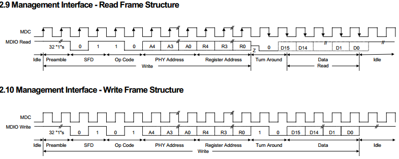
MDIO接口包括两根信号线:MDC和MDIO,通过它,MAC层芯片(或其它控制芯片)可以访问物理层芯片的寄存器,并通过这些寄存器来对物理层芯片进行控制和管理。MDIO管理接口如下:
MDC:管理接口的时钟,它是一个非周期信号,信号的最小周期(实际是正电平时间和负电平时间之和)为400ns,最小正电平时间和负电平时间为160ns,最大的正负电平时间无限制。它与TX_CLK和RX_CLK无任何关系。
MDIO是一根双向的数据线,用来传送MAC层的控制信息和物理层的状态信息。MDIO数据与MDC时钟同步,在MDC上升沿有效。MDIO管理接口的数据帧结构如:

图MDIO管理接口的数据帧结构
In read/write operation, the management data frame is 64-bits long and starts with 32 contiguous logic one bits (preamble) synchronization clock cycles on MDC. The Start of Frame Delimiter (SFD) is indicated by a <01> pattern followed by the operation code (OP):<10> indicates Read operation and <01> indicates Write operation. For read operation, a 2-bit turnaround (TA) filing between Register Address field and Data field is provided for MDIO to avoid contention. Following the turnaround time, 16-bit data is read from or written onto management registers.
帧结构各域的含义如下:
PRE:帧前缀域,为32个连续“1”比特,这帧前缀域不是必要的,某些物理层芯片的MDIO操作就没有这个域。
ST:帧开始标志,出现“01”比特表示帧设计开始。
OP:帧操作码,比特“10”表示此帧为读操作帧,比特“01”表示此帧为写操作帧。
PHYAD:物理层芯片的地址,5个比特,每个芯片都把自己的地址与这5个比特进行比较,若匹配则响应后面的操作,若不匹配,则忽略掉后面的操作。
REGAD:用来选择物理层芯片的32个寄存器中的某个寄存器的地址。
TA:状态转换域,若为读操作,则第一比特时MDIO为高阻态,第二比特时由物理层芯片使MDIO置“0”。若为写操作,则MDIO仍由MAC层芯片控制,其连续输出“10”两个比特。
DATA:帧的寄存器的数据域,16比特,若为读操作,则为物理层送到MAC层的数据,若为写操作,则为MAC层送到物理层的数据。
IDLE:帧结束后的空闲状态,此时MDIO无源驱动,处高阻状态,但一般用上拉电阻使其处在高电平,即MDIO引脚需要上拉电阻。
注:上述图片及英文来自“DM9161a数据手册”
四、网卡寄存器
寄存器分类
1. 若是PHY芯片,只存在MII寄存器即可,可直接访问,如dm9161a。
The DM9161A management functions correspond to MII specification for IEEE 802.3u-1995 (Clause 22) for registers 0 through 6 with vendor-specific registers 16,17, 18, 21, 22, 23 and 24.
2. 若是MAC+PHY芯片,则除了MII寄存器外,还存在芯片本身的控制状态寄存器,如dm9000cep。
The DM9000C implements several control and status registers, which can be accessed by the host. These CSRs are byte aligned. All CSRs are set to their default values by hardware or software reset unless they are specified
3. 有的网卡芯片(PHY)包含3类寄存器,如AR8033。
Three types of registers are present on AR8033:
>> IEEE defined 32 MII
registers, referred to as “registers” in this document
– MII registers are accessed directly through the management frame.
>> Atheros defined debug
registers, referred to as “debug registers” in this document
– Write debug offset address to 0x1D
– Read/write the data from/to 0x1E
>> IEEE defined MDIO Manageable
Device (MMD) register, referred to as “MMD registers” in this document
– MMD register access: refer to “MDIO Interface Register”.
Example: Writing 0x8000 to register 0 of MMD3.
1. Write 0x3 to register 0xD: 0xD = 0x0003; (function = address; set the device
address)
2. Write 0x0 to register 0xE: 0xE = 0x0; (set the register offset address)
3. Write 0x4003 to register 0xD:0xD=0x4003; (function = data; keep the device
address)
4. Read register 0xE:0xE == (data from register 0x0 of MMD3)
5. Write 0x8000 to register 0xE: 0xE = 0x8000 (write 0x8000 to register 0x0 of
MMD3)
NOTE: Read operation follows the
process 1 to 4.
MDIO interface registers are categorized to two groups:
>>MMD3 – MDIO Manageable Device Address 3 for PCS
>>MMD7 – MDIO Manageable Device Address 7 for Auto-Negotiation
寄存器访问
下面以ar8033为例说明寄存器访问情况。
ar8033的MII寄存器可以直接访问,debug寄存器和MDIO寄存器需要借助MII寄存器进行访问。
MDIO寄存器风味两组MMD3和MMD7,其访问需要借助MMD Access Control Register (0xD)和MMD Access Address Data Register (0xE)。

offset:0x0E, or 0d14

参考:
1. 教你怎样去选择合适的一款网卡

 浙公网安备 33010602011771号