Efficiently Drawing Multiple Instances of Geometry (Direct3D 9)
Given a scene that contains many objects that use the same geometry, you can draw many instances of that geometry at different orientations, sizes, colors, and so on with dramatically better performance by reducing the amount of data you need to supply to the renderer.
This can be accomplished through the use of two techniques: the first for drawing indexed geometry and the second for non-indexed geometry. Both techniques use two vertex buffers: one to supply geometry data and one to supply per-object instance data. The instance data can be a wide variety of information such as a transform, color data, or lighting data - basically anything that you can describe in a vertex declaration. Drawing many instances of geometry with these techniques can dramatically reduce the amount of data sent to the renderer.
Drawing Indexed Geometry
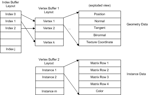
The vertex buffer contains per-vertex data that is defined by a vertex declaration. Suppose that part of each vertex contains geometry data, and part of each vertex contains per-object instance data, as shown in the following diagram.

This technique requires a device that supports the 3_0 vertex shader model. This technique works with any programmable shader but not with the fixed function pipeline.
For the vertex buffers shown above, here are the corresponding vertex buffer declarations:
const D3DVERTEXELEMENT9 g_VBDecl_Geometry[] =
{
{0,  0, D3DDECLTYPE_FLOAT3, D3DDECLMETHOD_DEFAULT, D3DDECLUSAGE_POSITION, 0},
{0, 12, D3DDECLTYPE_FLOAT3, D3DDECLMETHOD_DEFAULT, D3DDECLUSAGE_NORMAL,   0},
{0, 24, D3DDECLTYPE_FLOAT3, D3DDECLMETHOD_DEFAULT, D3DDECLUSAGE_TANGENT,  0},
{0, 36, D3DDECLTYPE_FLOAT3, D3DDECLMETHOD_DEFAULT, D3DDECLUSAGE_BINORMAL, 0},
{0, 48, D3DDECLTYPE_FLOAT2, D3DDECLMETHOD_DEFAULT, D3DDECLUSAGE_TEXCOORD, 0},
D3DDECL_END()
};

const D3DVERTEXELEMENT9 g_VBDecl_InstanceData[] =
{
{1, 0,  D3DDECLTYPE_FLOAT4, D3DDECLMETHOD_DEFAULT, D3DDECLUSAGE_TEXCOORD, 1},
{1, 16, D3DDECLTYPE_FLOAT4, D3DDECLMETHOD_DEFAULT, D3DDECLUSAGE_TEXCOORD, 2},
{1, 32, D3DDECLTYPE_FLOAT4, D3DDECLMETHOD_DEFAULT, D3DDECLUSAGE_TEXCOORD, 3},
{1, 48, D3DDECLTYPE_FLOAT4, D3DDECLMETHOD_DEFAULT, D3DDECLUSAGE_TEXCOORD, 4},
{1, 64, D3DDECLTYPE_FLOAT4, D3DDECLMETHOD_DEFAULT, D3DDECLUSAGE_COLOR,    0},
D3DDECL_END()
};
These declarations define two vertex buffers. The first declaration (for stream 0, indicated by the zeros in column 1) defines the geometry data which consists of: position, normal, tangent, binormal, and texture coordinate data.
The second declaration (for stream 1, indicated by the ones in column 1) defines the per-object instance data. Each instance is defined by four four-component floating point numbers, and a four-component color. The first four values could be used to initialize a 4x4 matrix, which means that this data will uniquely size, position, and rotate each instance of the geometry. The first four components use a texture coordinate semantic which, in this case, means "this is a general four-component number." When you use arbitrary data in a vertex declaration, use a texture coordinate semantic to mark it. The last element in the stream is used for color data. This could be applied in the vertex shader to give each instance a unique color.
Before rendering, you need to call SetStreamSourceFreq to bind the vertex buffer streams to the device. Here is an example that binds both vertex buffers:
// Set up the geometry data stream
pd3dDevice->SetStreamSourceFreq(0,
    (D3DSTREAMSOURCE_INDEXEDDATA | g_numInstancesToDraw));
pd3dDevice->SetStreamSource(0, g_VB_Geometry, 0,
    D3DXGetDeclVertexSize( g_VBDecl_Geometry, 0 ));

// Set up the instance data stream
pd3dDevice->SetStreamSourceFreq(1,
    (D3DSTREAMSOURCE_INSTANCEDATA | 1));
pd3dDevice->SetStreamSource(1, g_VB_InstanceData, 0,
    D3DXGetDeclVertexSize( g_VBDecl_InstanceData, 1 ));
SetStreamSourceFreq uses D3DSTREAMSOURCE_INDEXEDDATA to identify the indexed geometry data. In this case, stream 0 contains the indexed data that describes the object geometry. This value is logically combined with the number of instances of the geometry to draw.
Note that D3DSTREAMSOURCE_INDEXEDDATA and the number of instances to draw must always be set in stream zero.
In the second call, SetStreamSourceFreq uses D3DSTREAMSOURCE_INSTANCEDATA to identify the stream containing the instance data. This value is logically combined with 1 since each vertex contains one set of instance data.
The last two calls to SetStreamSource bind the vertex buffer pointers to the device.
When you are finished rendering the instance data, be sure to reset the vertex stream frequency back to its default state (which does not use instancing). Because this example used two streams, set both streams as shown below:
pd3dDevice->SetStreamSourceFreq(0,1);
pd3dDevice->SetStreamSourceFreq(1,1);
Indexed Geometry Performance Comparison
While it is not possible to make a single conclusion about how much this technique could reduce the render time in every application, consider the difference in the amount of data streamed into the runtime and the number of state changes that will be reduced if you use the instancing technique. This render sequence takes advantage of drawing multiple instances of the same geometry:
if( SUCCEEDED( pd3dDevice->BeginScene() ) )
{
    // Set up the geometry data stream
    pd3dDevice->SetStreamSourceFreq(0,
                (D3DSTREAMSOURCE_INDEXEDDATA | g_numInstancesToDraw));
    pd3dDevice->SetStreamSource(0, g_VB_Geometry, 0,
                D3DXGetDeclVertexSize( g_VBDecl_Geometry, 0 ));

    // Set up the instance data stream
    pd3dDevice->SetStreamSourceFreq(1,
                (D3DSTREAMSOURCE_INSTANCEDATA | 1));
    pd3dDevice->SetStreamSource(1, g_VB_InstanceData, 0,
                D3DXGetDeclVertexSize( g_VBDecl_InstanceData, 1 ));

    pd3dDevice->SetVertexDeclaration( ... );
    pd3dDevice->SetVertexShader( ... );
    pd3dDevice->SetIndices( ... );

    pd3dDevice->DrawIndexedPrimitive( D3DPT_TRIANGLELIST, 0, 0,
                g_dwNumVertices, 0, g_dwNumIndices/3 );

    pd3dDevice->EndScene();
}
Notice that the render loop is called once, the geometry data is streamed once, and n instances are streamed once. This next render sequence is identical in functionality, but does not take advantage of instancing:
if( SUCCEEDED( pd3dDevice->BeginScene() ) )
{
    for(int i=0; i < g_numObjects; i++)
    {
        pd3dDevice->SetStreamSource(0, g_VB_Geometry, 0,
                D3DXGetDeclVertexSize( g_VBDecl_Geometry, 0 ));


        pd3dDevice->SetVertexDeclaration( ... );
        pd3dDevice->SetVertexShader( ... );
        pd3dDevice->SetIndices( ... );

        pd3dDevice->DrawIndexedPrimitive( D3DPT_TRIANGLELIST, 0, 0,
                g_dwNumVertices, 0, g_dwNumIndices/3 );
    }

    pd3dDevice->EndScene();
}
Notice that the entire render loop is wrapped by a second loop to draw each object. Now the geometry data is streamed into the renderer n times (instead of once) and any pipeline states may also be set redundantly for each object drawn. This render sequence is very likely to be significantly slower. Notice also that the parameters to DrawIndexedPrimitive have not changed between the two render loops.


【推荐】国内首个AI IDE,深度理解中文开发场景,立即下载体验Trae
【推荐】编程新体验,更懂你的AI,立即体验豆包MarsCode编程助手
【推荐】抖音旗下AI助手豆包,你的智能百科全书,全免费不限次数
【推荐】轻量又高性能的 SSH 工具 IShell:AI 加持,快人一步
· 被坑几百块钱后,我竟然真的恢复了删除的微信聊天记录!
· 没有Manus邀请码?试试免邀请码的MGX或者开源的OpenManus吧
· 【自荐】一款简洁、开源的在线白板工具 Drawnix
· 园子的第一款AI主题卫衣上架——"HELLO! HOW CAN I ASSIST YOU TODAY
· Docker 太简单,K8s 太复杂?w7panel 让容器管理更轻松!