跨云平台与物理专线使用Vxlan实现两地二层互通,并使用ospf与bgp做底层链路主备
个人博客地址
Vxlan基础,已掌握可略过
VXLAN网络架构
VXLAN是NVO3中的一种网络虚拟化技术,通过将原主机发出的数据包封装在UDP中,并使用物理网络的IP、MAC作为外层头进行封装,然后在IP网络上传输,到达目的地后由隧道终结点解封装并将数据发送给目标主机。
通过VXLAN,虚拟网络可接入大量租户,且租户可以规划自己的虚拟网络,不需要考虑物理网络IP地址和广播域的限制,降低了网络管理的难度,同时满足虚拟机迁移和多租户的需求。
类似于传统的VLAN网络,VXLAN网络也有VXLAN网络内互访和VXLAN网络间互访。

VXLAN网络内互访
通过VXLAN技术可以实现在已有三层网络上构建虚拟二层网络,实现主机之间的二层互通
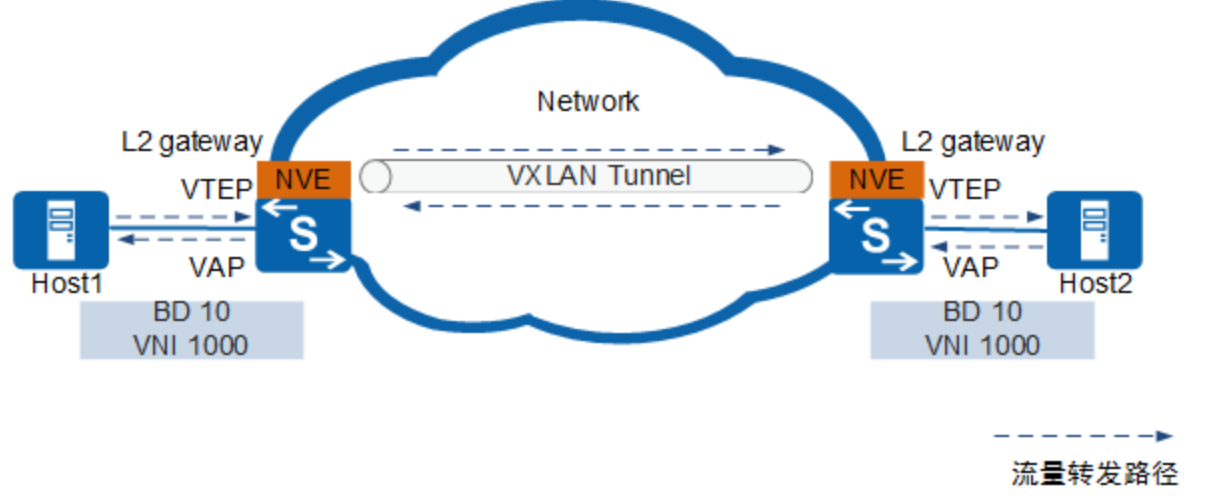
VXLAN网络内互访中涉及的概念如下:
-
网络标识VNI(VXLAN Network Identifier)
类似于传统网络中的VLAN ID,用于区分VXLAN段,不同VXLAN段的租户不能直接进行二层通信。一个租户可以有一个或多个VNI,VNI由24比特组成,支持多达16M的租户。
-
广播域BD(Bridge Domain)
类似传统网络中采用VLAN划分广播域方法,在VXLAN网络中通过BD划分广播域。
在VXLAN网络中,将VNI以1:1方式映射到广播域BD,一个BD就表示着一个广播域,同一个BD内的主机就可以进行二层互通。
-
VXLAN隧道端点VTEP(VXLAN Tunnel Endpoints)
VTEP可以对VXLAN报文进行封装和解封装。
VXLAN报文中源IP地址为源端VTEP的IP地址,目的IP地址为目的端VTEP的IP地址。一对VTEP地址就对应着一条VXLAN隧道。在源端封装报文后通过隧道向目的端VTEP发送封装报文,目的端VTEP对接收到的封装报文进行解封装。
-
虚拟接入点VAP(Virtual Access Point)
VXLAN业务接入点,可以基于VLAN或报文流封装类型接入业务:- 基于VLAN接入业务:在VTEP上建立VLAN与BD的一对一或多对一的映射。这样,当VTEP收到业务侧报文后,根据VLAN与BD的映射关系,实现报文在BD内进行转发。
- 基于报文流封装类型接入业务:在VTEP连接下行业务的物理接口上创建二层子接口,并配置不同的流封装类型,使得不同的接口接入不同的数据报文。同时,将二层子接口与BD进行一一映射。这样业务侧报文到达VTEP后,即会进入指定的二层子接口。即根据二层子接口与BD的映射关系,实现报文在BD内进行转发。
-
网络虚拟边缘NVE(Network Virtualization Edge)
NVE是实现网络虚拟化功能的网络实体。报文经过NVE封装转换后,NVE间就可基于三层基础网络建立二层虚拟化网络。
-
二层网关
类似传统网络的二层接入设备,在VXLAN网络中通过二层网关解决租户接入VXLAN虚拟网络,也可用于同一VXLAN虚拟网络的子网通信。
VXLAN网络间互访(集中式网关)
不同BD之间的主机不能直接进行二层通信,需要通过VXLAN三层网关实现主机间的三层通信。
集中式网关是指将三层网关集中部署在一台设备上,所有跨子网的流量都经过三层网关进行转发,实现流量的集中管理。
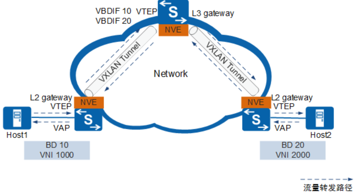
VXLAN网络间互访中涉及的概念如下:
-
三层网关
类似传统网络中不同VLAN的用户间不能直接进行二层互访,不同VNI之间的VXLAN及VXLAN和非VXLAN之间也不能直接相互通信。为了使VXLAN之间,以及VXLAN和非VXLAN之间能够进行通信,引入了VXLAN三层网关的概念。
三层网关用于VXLAN虚拟网络的跨子网通信以及外部网络的访问。
-
VBDIF接口
类似于传统网络中采用VLANIF解决不同广播域互通的方法,在VXLAN中引入了VBDIF的概念。
VBDIF接口在VXLAN三层网关上配置,是基于BD创建的三层逻辑接口。通过VBDIF接口配置IP地址可实现不同网段的VXLAN间,及VXLAN和非VXLAN的通信,也可实现二层网络接入三层网络。
VXLAN网络间互访(分布式网关)
分布式网关是指将VXLAN二层网关和三层网关部署在同一台设备上,VTEP设备既作为VXLAN网络中的二层网关设备,与主机对接,用于解决终端租户接入VXLAN虚拟网络的问题。同时也作为VXLAN网络中的三层网关设备,实现跨子网的终端租户通信,以及外部网络的访问。仅BGP EVPN方式部署VXLAN网络时支持分布式网关。
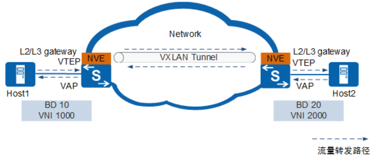
VXLAN分布式网关具有如下特点:
- 同一个VTEP节点既可以做VXLAN二层网关,也可以做VXLAN三层网关,部署灵活。
- VTEP节点只需要学习自身连接服务器的ARP表项,而不必像集中式三层网关一样,需要学习所有服务器的ARP表项,解决了集中式三层网关带来的ARP表项瓶颈问题,网络规模扩展能力强
VXLAN报文封装格式
原始报文在封装过程中先被添加一个VXLAN帧头,再被封装在UDP报头中,并使用承载网络的IP、MAC地址作为外层头进行封装。
报文封装格式
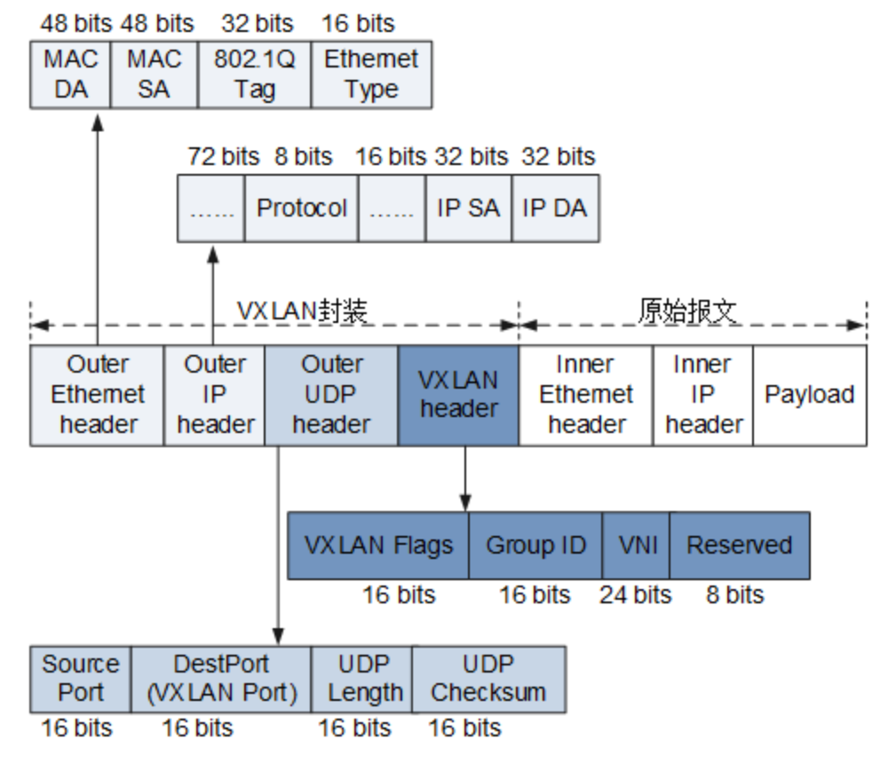
现网实现方案
拓扑
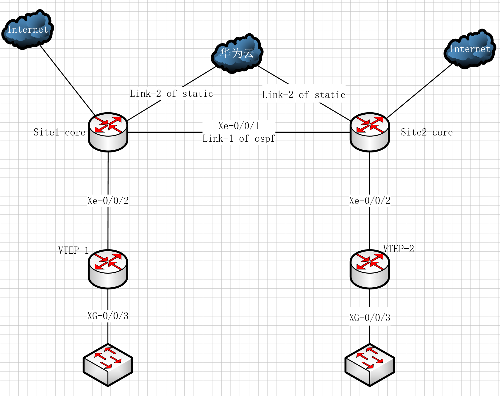
拓扑描述
两个pop点均为IDC机房,拥有完整架构,以上拓扑主要摘出Vxlan相关设备,Site-1与Site-2间通过物理专线直连,同时两个Site同时使用物理专线接入华为云,在华为云购买云连接并配置路由打通两个站点
华为云与站点间使用静态路由方式(国内云平台BGP是伪BGP,不能根据线下通告的路由自动同步),直连专线链路使用ospf互联,site-2接入互联网
需求
- 两个站点服务器二层互通
- site-2互联网ip可以在site-1使用
- 优先使用云联网,直连专线做备用
- 主备倒换控制在毫秒级
需求分析
- 需求1要求两个site间实现二层互通,可以使用VPLS VLL Vxlan技术实现
- 需求2可以使用跨云平台GRE隧道或Vxlan技术实现
- 需求3与需求4根据需求1 2 来指定倒换方案
- 现网core设备为juniper mx系列,系统版本不支持RPM联动静态路由,也不支持跨条BFD检测,故无法使用浮动静态路由方式来做两端Vtep ip互通
- 同时云平台线路非直连不能建立ospf peer,所以也不能使用ospf主备路由方式做负载
综上,由于接入云平台所以不能建立完整mpls lsp 如果使用VPLS或VLL只能使用GRE承载PW会增大额外开销,且需求2还需独立实现,综合考虑最终选择使用Vxlan技术实现,根据最后两条分析决定跨云平台建立bgp与直连专线ospf两个协议间做主备。
方案配置
地址规划
| 设备 | loopback地址 | 物理专线互联地址 | 云平台互联地址 |
| Site1-core | 192.168.39.5/32 | 10.38.0.1/30 | 10.39.0.1/30 |
| Site2-core | 192.168.39.21/32 | 10.38.0.2/30 | 10.39.0.5/30 |
| Vtep-1 | 192.168.39.1/30 | 10.40.0.2/30 | |
| Vtep-2 | 192.168.39.17/30 | 10.40.0.6/30 |
配置
基础线路主备
#Site1-core
set protocols bgp group Vxlan type external
set protocols bgp group Vxlan neighbor 192.168.39.21 multihop ttl 10
set protocols bgp group Vxlan neighbor 192.168.39.21 local-address 192.168.39.5
set protocols bgp group Vxlan neighbor 192.168.39.21 import Vxlanin
set protocols bgp group Vxlan neighbor 192.168.39.21 export Vxlanout
set protocols bgp group Vxlan neighbor 192.168.39.21 peer-as 65500
set protocols bgp group Vxlan neighbor 192.168.39.21 local-as 65501
set protocols bgp group Vxlan neighbor 192.168.39.21 bfd-liveness-detection minimum-interval 100
set protocols bgp group Vxlan neighbor 192.168.39.21 bfd-liveness-detection minimum-receive-interval 100
set protocols bgp group Vxlan neighbor 192.168.39.21 bfd-liveness-detection multiplier 3

set policy-options policy-statement Vxlanin term Vxlan from route-filter 192.168.39.17/32 exact
set policy-options policy-statement Vxlanin term Vxlan then accept
set policy-options policy-statement Vxlanin term 99 then reject

set policy-options policy-statement Vxlanout term Vxlan from route-filter 192.168.39.1/32 exact
set policy-options policy-statement Vxlanout term Vxlan then accept
set policy-options policy-statement Vxlanout term 99 then reject

set protocols ospf area 0.0.0.0 interface xe-0/0/1.33 bfd-liveness-detection minimum-receive-interval 100
set protocols ospf area 0.0.0.0 interface xe-0/0/1.33 bfd-liveness-detection multiplier 3
set protocols ospf area 0.0.0.0 interface xe-0/0/1.33 bfd-liveness-detection transmit-interval minimum-interval 100
set protocols ospf area 0.0.0.0 interface xe-0/0/2.100 bfd-liveness-detection minimum-receive-interval 100
set protocols ospf area 0.0.0.0 interface xe-0/0/2.100 bfd-liveness-detection multiplier 3
set protocols ospf area 0.0.0.0 interface xe-0/0/2.100 bfd-liveness-detection transmit-interval minimum-interval 100

set routing-options static route 192.168.39.21/32 next-hop 10.39.0.2
set routing-options static route 192.168.39.1/32 next-hop 10.40.0.2

#Site2-core
set protocols bgp group Vxlan type external
set protocols bgp group Vxlan family inet unicast rib-group fbf-group
set protocols bgp group Vxlan neighbor 192.168.39.5 multihop ttl 10
set protocols bgp group Vxlan neighbor 192.168.39.5 local-address 192.168.39.21
set protocols bgp group Vxlan neighbor 192.168.39.5 import Vxlanin
set protocols bgp group Vxlan neighbor 192.168.39.5 export Vxlanout
set protocols bgp group Vxlan neighbor 192.168.39.5 peer-as 65501
set protocols bgp group Vxlan neighbor 192.168.39.5 local-as 65500
set protocols bgp group Vxlan neighbor 192.168.39.5 bfd-liveness-detection minimum-interval 100
set protocols bgp group Vxlan neighbor 192.168.39.5 bfd-liveness-detection minimum-receive-interval 100
set protocols bgp group Vxlan neighbor 192.168.39.5 bfd-liveness-detection multiplier 3

set policy-options policy-statement Vxlanin term Vxlan from route-filter 192.168.39.1/32 exact
set policy-options policy-statement Vxlanin term Vxlan then accept
set policy-options policy-statement Vxlanin term 99 then reject
set policy-options policy-statement Vxlanout term Vxlan from route-filter 192.168.39.17/32 exact
set policy-options policy-statement Vxlanout term Vxlan then accept
set policy-options policy-statement Vxlanout term 99 then reject

set protocols ospf area 0.0.0.0 interface xe-0/0/1.33 bfd-liveness-detection minimum-receive-interval 100
set protocols ospf area 0.0.0.0 interface xe-0/0/1.33 bfd-liveness-detection multiplier 3
set protocols ospf area 0.0.0.0 interface xe-0/0/1.33 bfd-liveness-detection transmit-interval minimum-interval 100

set routing-options static route 192.168.39.5/32 next-hop 10.39.0.6
set routing-options static route 192.168.39.17/32 next-hop 10.40.0.6


set protocols ospf area 0.0.0.0 interface xe-0/0/2.100 bfd-liveness-detection minimum-receive-interval 100
set protocols ospf area 0.0.0.0 interface xe-0/0/2.100 bfd-liveness-detection multiplier 3
set protocols ospf area 0.0.0.0 interface xe-0/0/2.100 bfd-liveness-detection transmit-interval minimum-interval 100
Vxlan配置
#Vtep-1

interface LoopBack1
 ip address 192.168.39.1 255.255.255.252
 ospf network-type broadcast
 ospf enable 1 area 0.0.0.0

bridge-domain 590
 l2 binding vlan 520
 vxlan vni 1001
bridge-domain 600
 l2 binding vlan 590
 vxlan vni 1002

interface Nve1
 source 192.168.39.1
 vni 1001 head-end peer-list 192.168.39.17
 vni 1002 head-end peer-list 192.168.39.17

interface XGigabitEthernet0/0/3
port link-type trunk
undo port trunk allow-pass vlan 1
port trunk allow-pass vlan 520  590

#Vtep-2
interface LoopBack1
 ip address 192.168.39.17 255.255.255.252
 ospf network-type broadcast
 ospf enable 1 area 0.0.0.0

bridge-domain 590
 l2 binding vlan 520
 vxlan vni 1001
bridge-domain 600
 l2 binding vlan 590
 vxlan vni 1002

interface Nve1
 source 192.168.39.17
 vni 1001 head-end peer-list 192.168.39.1
 vni 1002 head-end peer-list 192.168.39.1

interface XGigabitEthernet0/0/3
port link-type trunk
undo port trunk allow-pass vlan 1
port trunk allow-pass vlan  590
以上配置可实现两个Site中服务器打上vlan 590标签就可实现二层互通,Vtep-1服务器打上vlan 520就可以使用Vtep-2互联网地址
注意由于封装了Vxlan头部,物理线路包括云平台MTU需要调整,最小调整为1550,或者服务器端MTU调整为1450,否则会影响传输效率,实测10G带宽最大利用率为10%


 浙公网安备 33010602011771号