[转]FPGA实践——基于ROM访问的直接波形合成
本文原创,转载请注明出处:http://www.cnblogs.com/risten/p/4166169.html
1.系统原理
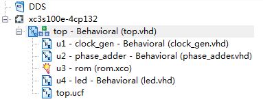
通过频率控制字选择相位步进,产生访问ROM的地址,进而控制DAC的输出波形与频率。整个系统由时钟生成、相位累加、ROM、DAC组成。限于basys2开发板的限制,本次将输出DAC替换为8个led灯显示。
2.系统设计

2.1 时钟生成
 1 library IEEE;
 2 use IEEE.STD_LOGIC_1164.ALL;
 3 use IEEE.STD_LOGIC_ARITH.ALL;
 4 use IEEE.STD_LOGIC_UNSIGNED.ALL;
 5
 6 entity clock_gen is
 7 port (
 8         clk        :    IN        STD_LOGIC;
 9         rst        :    IN        STD_LOGIC;
10         clka        :    OUT    STD_LOGIC
11         );
12 end clock_gen;
13
14 architecture Behavioral of clock_gen is
15 signal    cnt        :    INTEGER;
16 signal    clk_reg    :    STD_LOGIC;
17
18 begin
19 clka<=clk_reg;
20 process(clk,rst)
21 begin
22 if    (rst='0')    then
23     cnt<=0;
24     clk_reg<='0';
25 elsif    (clk'event and clk='1') then
26     if (cnt=250000) then    --生成时钟为0.01s
27         cnt<=0;
28         clk_reg<=not clk_reg;
29     else
30         cnt<=cnt+1;
31     end if;
32 end if;
33 end process;
34 end Behavioral;
2.2相位累加(地址生成)
 1 library IEEE;
 2 use IEEE.STD_LOGIC_1164.ALL;
 3 use IEEE.STD_LOGIC_ARITH.ALL;
 4 use IEEE.STD_LOGIC_UNSIGNED.ALL;
 5
 6 entity phase_adder is
 7 port(
 8         clka        :    IN        STD_LOGIC;
 9         rst        :    IN        STD_LOGIC;
10         f_level    :    IN        STD_LOGIC_VECTOR(6 DOWNTO 0);
11         addr        :    OUT    STD_LOGIC_VECTOR(9 DOWNTO 0)
12         );
13 end phase_adder;
14
15 architecture Behavioral of phase_adder is
16 signal    cnt        :    STD_LOGIC_VECTOR(9 DOWNTO 0);
17
18 begin
19 addr<=cnt;
20 process(clka,rst,f_level)
21 begin
22 if    (rst='0')    then
23     cnt<=(others=>'0');
24 elsif    (clka'event and clka='1') then
25     cnt<=cnt+f_level;
26 end if;
27 end process;
28
29 end Behavioral;
2.3 ROM
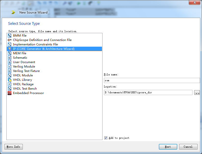
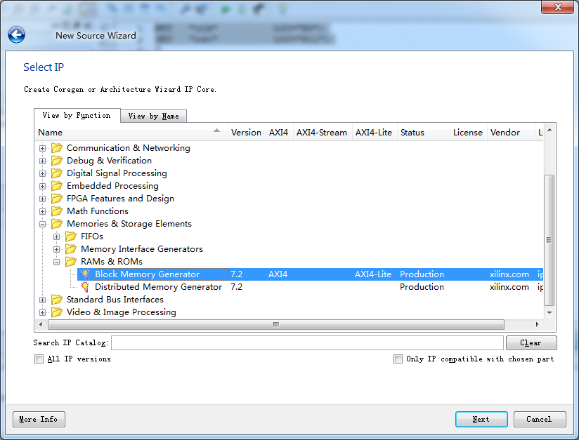
新建源文件选择IP核


存储类型

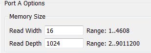
存储大小

数据初始化

正弦余弦初始化coe文件的生成(使用matlab)
 1 clc
 2 clear all
 3 close all
 4 x = linspace(0, 2*pi ,1024);     % 在区间[0,2*pi]之间等间隔地取1024个点
 5 y_cos = cos(x);
 6 y_sin = sin(x);
 7 y_cos = y_cos * 2^15;
 8 y_sin = y_sin * 2^15;
 9 fid = fopen('D:/cos.coe','wt');
10 fprintf(fid, '%5.0f,\n' , y_cos);
11 fclose(fid);
12 fid = fopen('D:/sin.coe','wt');
13 fprintf(fid, '%5.0f,\n' , y_sin);
14 fclose(fid);
用记事本在生成文件开头添加

并把最后的结尾换为 ; 号
存储器选项都设置完毕后点击generate即可。
2.4 LED显示(DAC)
 1 library IEEE;
 2 use IEEE.STD_LOGIC_1164.ALL;
 3 use IEEE.STD_LOGIC_ARITH.ALL;
 4 use IEEE.STD_LOGIC_UNSIGNED.ALL;
 5 use IEEE.STD_LOGIC_SIGNED.ALL;
 6
 7 entity led is
 8 port (
 9         data        :    IN        STD_LOGIC_VECTOR(15 DOWNTO 0);
10         led_seg    :    OUT    STD_LOGIC_VECTOR(7 DOWNTO 0)
11         );
12 end led;
13
14 architecture Behavioral of led is
15 begin
16 process(data)
17 begin
18 if (signed(data)<-24576) then
19     led_seg<="10000000";
20 elsif (signed(data)<-16348) then
21     led_seg<="01000000";
22 elsif (signed(data)<-8192) then
23     led_seg<="00100000";
24 elsif (signed(data)<0) then
25     led_seg<="00010000";
26 elsif (signed(data)<8192) then
27     led_seg<="00001000";
28 elsif (signed(data)<16348) then
29     led_seg<="00000100";
30 elsif (signed(data)<24576) then
31     led_seg<="00000010";
32 else
33     led_seg<="00000001";
34 end if;
35 end process;
36
37 end Behavioral;
2.5 顶层设计TOP
 1 library IEEE;
 2 use IEEE.STD_LOGIC_1164.ALL;
 3
 4 entity top is
 5 port (
 6         clk        :    IN        STD_LOGIC;
 7         rst        :    IN        STD_LOGIC;
 8         f_level    :    IN        STD_LOGIC_VECTOR(6 DOWNTO 0);
 9         led_seg    :    OUT    STD_LOGIC_VECTOR(7 DOWNTO 0)
10         );
11 end top;
12
13 architecture Behavioral of top is
14 COMPONENT clock_gen
15 PORT (
16         clk        :    IN        STD_LOGIC;
17         rst        :    IN        STD_LOGIC;
18         clka       :    OUT    STD_LOGIC
19         );
20 END COMPONENT;
21 COMPONENT phase_adder
22 PORT (
23         clka       :    IN        STD_LOGIC;
24         rst        :    IN        STD_LOGIC;
25         f_level    :    IN        STD_LOGIC_VECTOR(6 DOWNTO 0);
26         addr       :    OUT    STD_LOGIC_VECTOR(9 DOWNTO 0)
27         );
28 END COMPONENT;
29 COMPONENT rom
30 PORT (
31     clka : IN STD_LOGIC;
32     addra : IN STD_LOGIC_VECTOR(9 DOWNTO 0);
33     douta : OUT STD_LOGIC_VECTOR(15 DOWNTO 0)
34         );
35 END COMPONENT;
36 COMPONENT led
37 PORT (
38         data       :    IN        STD_LOGIC_VECTOR(15 DOWNTO 0);
39         led_seg    :    OUT    STD_LOGIC_VECTOR(7 DOWNTO 0)
40         );
41 END COMPONENT;
42
43 signal    clka        :    STD_LOGIC;
44 signal    addr        :    STD_LOGIC_VECTOR(9 DOWNTO 0);
45 signal    data        :    STD_LOGIC_VECTOR(15 DOWNTO 0);
46
47 begin
48 u1    :    clock_gen          PORT MAP (clk,rst,clka);
49 u2    :    phase_adder        PORT MAP (clka,rst,f_level,addr);
50 u3    :    rom                PORT MAP (clka,addr,data);
51 u4    :    led                PORT MAP    (data,led_seg);
52
53 end Behavioral;
3. 引脚定义
 1 NET    "clk"                LOC="B8";
 2 NET    "rst"                LOC="P11";
 3
 4 NET    "f_level<0>"    LOC="L3";
 5 NET    "f_level<1>"    LOC="K3";
 6 NET    "f_level<2>"    LOC="B4";
 7 NET    "f_level<3>"    LOC="G3";
 8 NET    "f_level<4>"    LOC="F3";
 9 NET    "f_level<5>"    LOC="E2";
10 NET    "f_level<6>"    LOC="N3";
11
12 NET    "led_seg<0>"    LOC="M5";
13 NET    "led_seg<1>"    LOC="M11";
14 NET    "led_seg<2>"    LOC="P7";
15 NET    "led_seg<3>"    LOC="P6";
16 NET    "led_seg<4>"    LOC="N5";
17 NET    "led_seg<5>"    LOC="N4";
18 NET    "led_seg<6>"    LOC="P4";
19 NET    "led_seg<7>"    LOC="G1";
欢迎阅读我的文章,如发现问题,请务必留言指正。
本博客内容除注明转载的内容外,均为作者原创,转载请注明原地址!
博客地址:http://www.cnblogs.com/connorzx/
希望在未来的日子里我和你共同进步。


