pressure coeffcient of a wing/blade - cfd post
software: CFD POST ANSYS, matlab
1. Extract data on cfd post
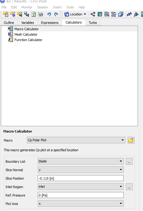
menu bar, select Tools > Macro Calculator.
 \
\
correction:
Ref pressure is relative pressure = abs pressure - reference pressure (in Fluent)
definitions;
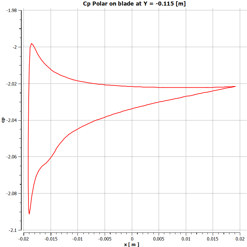
Cp expression can be defined
as:
(Pressure - $pref [Pa])/dynHead
-
Pressure: static pressure
- $pref : the Ref. Pressure set in the macro calculator
- dynHead : a reference dynamic head (evaluated at the inlet) that can be defined as:
0.5 * areaAve(Density)@inlet * areaAve(Velocity)@inlet^2
- dynHead is a reference dynamic head
The following information must be specified:
• Boundary List: A list of boundaries used in the simulation (blade).
• Slice Normal: The axis that will be normal to the slice plane.
• Slice Position: The offset of the slice plane in the direction specified by the normal axis.
• Inlet Region: The locator used to calculate inlet quantities.
• Ref. Pressure: The reference pressure for the simulation.
• Plot Axis: The axis on which the results will be plotted.
Note for moving reference frame
use pressure as y variable, if moving reference frame is used,
cause the 'velocity' is 'relative velocity'

2. matlab plotting
Code for ' pressure coefficient vs. x/c' in matlab
name: Cpr.m
% plot and save 'pressure coefficient vs. x/c'
load pressure_9r_7.1m.out;
pressure=pressure_9r_7_1m(:,2);
x=pressure_9r_7_1m(:,1);
x=x+0.0139;
x_nor=x/0.0276;
cp=pressure_coeff(pressure);  % user defined function
plot(x_nor,cp);
cp_x = [x_nor cp];
save -ascii presure_coeff_7.1m.txt cp_x
- pressure_coeff.m code is as below
function cp= pressure_coeff(p)
% v : velocity
% p :  pressure
% p0 :   reference pressure
% rho : density
% omega: angular velocity, rad/s
% r : radius
  r=0.207;
v = 0.6;
p0=0;
omega = 13.043;
rho = 998.2;
U = v^2 + (omega*r)^2;
cp=2*(p-p0)/(rho*U)
gnuplot script
#set terminal jpeg
#set output 'coeff_epp_gci.jpg'
#set terminal png
#set output 'pressure_tsr5.png'
set terminal postscript eps font 24
set out 'pressure_coeff_tsr5.eps'
#set terminal x11
set autoscale
unset log
unset label
unset pm3d
set key at graph .7, .4
set key spacing 1
set xtic auto
set ytic auto
set xlabel "x/c - Normalized chord length"
set xrange [*:*]
# r0 initial pulse
set yrange [*:*]

set ylabel "C_{pr} - Pressure coefficient"
set style line 1 lt 1 lc rgb "black" lw 4 pointtype 6
set style line 2 lt 2 lc rgb "black" lw 4 pointtype 2
set style line 3 lt 3 lc rgb "black" lw 4
set style line 4 lt 4 lc rgb "red" lw 4
set style line 5 lt 5 lc rgb "black" lw 4
set style line 6 lt 6 lc rgb "brown" lw 4
set pointsize 2
set bars 3
plot "presure_coeff_3.3m.txt" using 1:2  t  "3.5M" ls 1 with lines,\
"presure_coeff_5.4m.txt" using 1:2  t  "5.4M" ls 2 with lines,\
"presure_coeff_7.1m.txt" using 1:2  t  "7.1M" ls 3 with lines


 浙公网安备 33010602011771号