

stall and flow separation on airfoil or blade
stall
stall and flow separation
Table of Contents
1 Stall and flow separation
- Definition of stall/ flow sepration
features:
- low Cl
- flow separated from solid surface
- large Cd
- unsteady flow, and fluctuating Cl, Cd
1.1 Separation of Boundary Layers
Balmer, David (2003) Separation of Boundary Layers, from School of Engineering and Electronics, University of Edinburgh
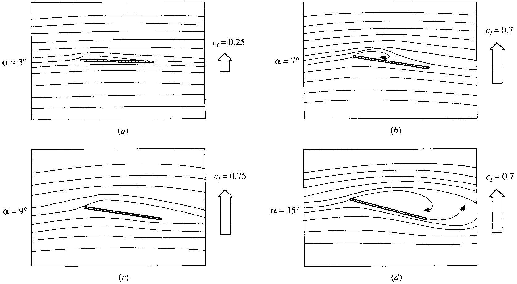
1.2 Types of stall
- Trailing -edge stall
- Leasing-edge stall
- Thin airfoil stall
- (soft stall ) the flow separation point starts at trailing edge and increases slowly with increasing AOA
- Normally for thick airfoil, e.g. NACA 4421
- (hard stall) abrupt flow separation near the leading edge (LE) without subsequent reattachment;
the separation starts at the leading edge of the aerofoil, the entire boundary layer may separate almost simultaneously
- thin airfoils, with thickness to chord ratio: 10- 16% (Figure 4.49, P389,Anserson,2010)
- flow separation at the LE with reattachment at a point which moves progressively rearward with increasing AOA.
The role of boundary-layer flow and separation processes in relation to stalling as well as the sensitivity of the stall to factors which influence boundary-layer growth, such as Reynolds number, is discussed in ~naca technical note 2502~1

Figure 1: TE stall naca 4421 (Fig.4.50 Anderson)

Figure 2: LE stall naca 4412 ( Anderson)

Figure 3: LE stall flat Plate ( Anderson)
1.3 Post stall airfoil data for BEM
experimental data for symmetric airfoil polar data steady-state data set from the Unsteady Aerodynamic Experiment rotor test2
1.3.1 Extraplolation methods:
- Viterna and Corrigan
aifoil polar extrapolation NACA0012 cl cd data >> Sheldahl, Robert E., and Paul C. Klimas. Aerodynamic characteristics of seven symmetrical airfoil sections through 180-degree angle of attack for use in aerodynamic analysis of vertical axis wind turbines. No. SAND-80-2114. Sandia National Labs., Albuquerque, NM (USA), 1981. naca0018 >> An Experimental and Numerical Assessment of Airfoil Polars for Use in Darrieus Wind Turbines—Part II: Post-stall Data Extrapolation Methods
- method 1
- Method 2
- extrapolate cl, cd up to the stall delay angle using the method proposed by Snel et al.5.
Further extrapolations beyond the stall delay angle were achieved using Viterna and Corrigan’s methodology for post stall predictions
- empirical correction
- used by batten 2008, University of Southampton
Airfoil polars measured in the wind tunnel or simulated with XFOIL or other CFD software are usually limited to small and medium inflow angles (e.g. -20° to +20° AoA). However the blades of both VAWTs and HAWTs often operate at high inflow angles. In order for the BEM routines to converge and produce reasonable results it is essential that the airfoil performance polars (Lift, Drag…and Moment coefficients) are extrapolated to a 360° inflow angle range.
Traditionally the method of Viterna has been extensively used for this purpose. However B. Montgomerie of the Swedish Defense Research Agency has also developed a polar extrapolation method for wind turbine applications. QBlade includes both methods thus allowing the user to use the full extrapolation flexibility of both.
If you have the chance to play around with various extrapolation parameters within QBlade you will notice how critical the airfoil 360° polar extrapolation is for the validity and accuracy of the BEM simulation results.
0 until the stall delay angle >> Snel et al. 5.
Further extrapolations beyond the stall delay angle were achieved using Viterna and Corrigan’s methodology for post stall predictions6 .
1.3.2 Reference
Robert E. Sheldahl, Paul C. Klimas aerodynamic characteristics of seven symmetrical airfoil sections through 180 degree angle of attack fo use in aerodynamic analysis of vertical axis wind turbines
NREL, 2004, Wind Turbine Post-Stall Airfoil Performance Characteristics Guidelines for Blade-Element Momentum Methods
Bianchini A, Balduzzi F, Rainbird JM, et al. An Experimental and Numerical Assessment of Airfoil Polars for Use in Darrieus Wind Turbines—Part II: Post-stall Data Extrapolation Methods. ASME. J. Eng. Gas Turbines Power. 2015;138(3):032603-032603-10. 10.1115/1.4031270.
MONTGOMERIE, B: Methods for Root Effects, Tip Effects and Extending the Angle of Attack Range to +-100deg, with Application to Aerodynamics for Blades on Wind Turbines and Propellers, FOI Swedish Defense Research Agency, Scien-tific Report FOI-R-1035-SE, 2004
VITERNA, L.A.; C ORRIGAN, R.D.: Fixed Pitch Rotor Performance of Large Horizontal Axis Wind Turbines, NASA Lewis Research Center, Cleveland, Ohio,1982
> Viterna, L .A., and Janetzke, D. C., “Theoretical and Experimental Power from Large Horizontal-Axis Wind Turbines,” NASA TM-82944, Sept 1982.
1.4 Parameters affects stall
- Re
- surface roughness
- free-stream turbulence
1.5 Dynamic Stall Dynamic_Stall
What is dynamic stall?
- stall delay
- flow separation is delayed to higher AOAs that would
otherwise occur under static (steady) conditions, followed by an abrupt flow separation from the LE of the airfoil (Leishman 2011)
Why ?
- unsteady flow seen by the blade
- When does dynamic stall happened?
at what condition will dynamic stall happen? Dynamic stall happens when the relative velocity seen by the blade is changing with time due to wind shear, yaw/tilt misalighment tower passage, and atmospheric turbulence.(hansen)
- How is lift/drag affected by dynamic stall?
a loop in Cl
Figure 9.9 Cl vs AOA using a dynamic stall model (hansen) 
- Features:
- force/load on blade isn't appear instantaneously when the AOA changes, there is a time delay
time delay ~ c/Vrel
- c: chord length
- Vrel : relative velocity seen at the blade section
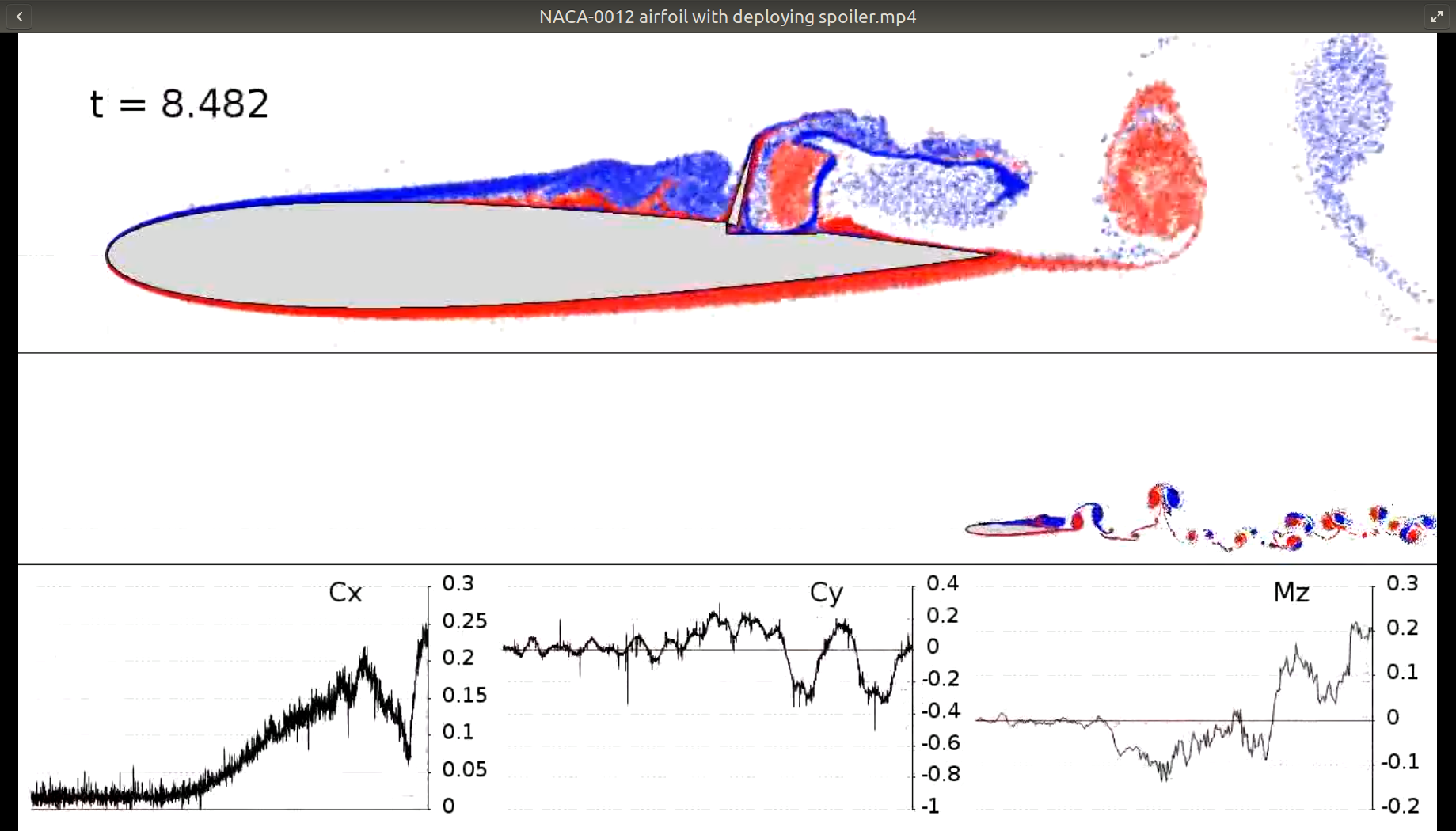
1.5.1 Numerical simulation of dynamic stall
naca0020 at Re 2e4 aoa=20 degree 7 7 Rosti, Marco. Direct numerical simulation of an aerofoil at high angle of attack and its control. Diss. City, University of London, 2016. a review 8 RANS is difficult for stall simulation Wang et al research showed that the size and position of the dynamic stall voretx obtained from SST K-ω doesn't match well with experimental results (Rec=1e5). Dumlupinar and Murthy 9 further investigated the performances of various turbulence models and pointed out that different turbulence closures predict a broad range of different behaviours even in the light stall case.
8 J A Ekaterinaris and M F Platzer. Computational prediction of airfoil dynamic stall. Progress in Aerospace Sciences, 33(11):759–846, 1998.
1.5.2 Dynamic Stall Model
- Attached flow >> Therdorsen theory
- Theodorsen theory for unsteady lift and aerodynamic moment (Theodorsen, 1935)
- Trailing edge stall >> Øye (1991)
- Leading edge separation >> The Beddoes–Leishman model (Leishman and Beddoes, 1989)
1.6 visualization
1.7 Researcher
Leishman and Beddoes 1986, 1989; Pierce and Hansen 1995; Pierce 1996; Leishman 2011; Damiani 2011.
1.8 Numerical Modelling
1.8.1 Turbulence Model for Stalled airfoil
keywords: Turbulence model; Flow separation; Stall
- SST K-ω
- For NACA0018, The k-ω SST model overpredict the drag coefficient
when AOA vairies between 30 and 150 degree.10
- failed to capture the lift at AOA between 150 and 180 degrees.
- unsteady >> k-τ model and adaptive k-τ model
steady >> Spalart Almaras 11
1.9 Visualization
1.10 References
- 4.13, Anderson
- Spera (1994) eggleston and stoddard(1987)
- Viterna, L. A. and Corrigan, R. D. (1981) Fixed pitch rotor performance of large horizontal axis wind turbines.
Proc. Workshop on Large Horizontal Axis Wind Turbines, NASA CP-2230, DOE Publication CONF-810752, 69–85, NASA Lewis Research Center, Cleveland, OH.
1.10.1 PhD Thesis
walker, John Scott 2018 Dynamic loading and stall of clean and fouled tidal turbine blade sections
1.10.2 others
Leishman, J. G. and Beddoes, T. S. (1989) ‘A semi-empirical model for dynamic stall’, Journal of the American Helicopter Society, vol 34, no 3, pp3–17
Schepers, J. G. and Snel, H. (1995) Dynamic Inflow: Yawed Conditions and Partial Span Pitch Control, ECN-C- -95-056, Petten, The Netherlands
Snel, H. and Schepers, J. G. (1995) Joint Investigation of Dynamic Inflow Effects and Implementation of an Engineering Method, ECN-C- -94-107, Petten, The Netherlands
Theodorsen, T. (1935) ‘General theory of aerodynamic instability and the mechanism of flutter’, NACA report no 496, National Advisory Committee for Aeronautics, pp413–433
Øye, S. (1991) ‘Dynamic stall, simulated as a time lag of separation’, in K. F. McAnulty (ed) Proceedings of the 4th IEASymposium on the Aerodynamics of Wind Turbines, ETSU-N-118, Harwell Laboratory, Harwell, UK
Pablo 2018 J. Fluids Eng, Effect of Blade Cambering on Dynamic Stall in View of Designing Vertical Axis Turbines doi: 10.1115/1.4039235
4.6 Burton, wind energy handbook
ch9 hansen, aerodynamics of wind turbine
Bramwell, A. R. S. (1976) Helicopter Dynamics, Edward Arnold Ltd, London
Hansen, M. 2004) ‘A Beddoes–Leishman type dynamic stall model in state-space and indicial formulations’, Risoe-R-1354(EN), Roskilde, Denmark
Footnotes:
Mccullough, Goerge B., and Donald E. Gault. "Examples of three representative types of airfoil-section stall at low speed." (1951).
James L. Tangler, 2005 Wind Turbine Post-Stall Airfoil Performance Characteristics Guidelines for Blade-Element Momentum Methods
Post stall data >> Extrapolation
why extrapolate data rather than measurement in lab experiment?
- Stall is difficult to quantify experimentally
DEFINITION NOT FOUND.
DEFINITION NOT FOUND.
DEFINITION NOT FOUND.
DEFINITION NOT FOUND.
DEFINITION NOT FOUND.
DEFINITION NOT FOUND.
DEFINITION NOT FOUND.
Bianchini, Alessandro, et al. "An Experimental and Numerical Assessment of Airfoil Polars for Use in Darrieus Wind Turbines—Part II: Post-stall Data Extrapolation Methods." Journal of Engineering for Gas Turbines and Power 138.3 (2016): 032603.
Stockdill, B., et al. "Simulation of unsteady turbulent flow over a stalled airfoil." Computational Fluid Dynamics Journal 14.4 (2006): 359.

 浙公网安备 33010602011771号