naca0012
naca0012
naca0012
Table of Contents
1 NACA0012 lift and drag from 0-180
naca0012 polar.doc
- drag polar
- Cl vs Cd at AOA 0-90 degree
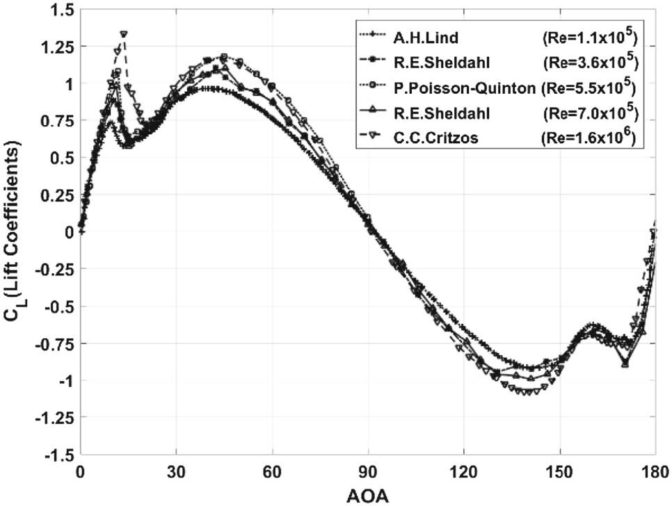
numerical results of lift, drag, and presure coefficients at Re=1e5 based on RANS Spalart– Allmaras turbulence model, two peak Cl at AOA 11.5 and 42 degree 1
Re - 2-88 x 106 and 1.44 x 10 63
experimental data 4
naca 0018 comparing experimental vs cfd vs post-stall correction 5
2  Marco 2016 Direct numerical simulation of an aerofoil at high angle of


1.1 Data– Cl Cd vs. aoa
Sheldahl, 1981 Sheldahl, Robert E., and Paul C. Klimas. Aerodynamic characteristics of seven symmetrical airfoil sections through 180-degree angle of attack for use in aerodynamic analysis of vertical axis wind turbines. No. SAND-80-2114. Sandia National Labs., Albuquerque, NM (USA), 1981. Re=4e4 AOA Cl Cd 0 0 0.0175 1 0.11 0.0177 2 0.22 0.0181 3 0.3376 0.0189 4 0.4464 0.0199 5 0.5276 0.0218 6 0.6115 0.0232 8 0.0615 0.072 10 0.0344 0.1 11 0.0869 0.117 12 0.1406 0.134 13 0.1945 0.152 14 0.2484 0.171 15 0.3024 0.19 16 0.3563 0.21 17 0.4107 0.231 18 0.4644 0.252 19 0.5178 0.274 20 0.5708 0.297 21 0.6232 0.32 22 0.6755 0.344 23 0.7283 0.369 24 0.7809 0.394 25 0.834 0.42 26 0.8873 0.446 27 0.9407 0.473 30 0.915 0.57 35 1.02 0.745 40 1.075 0.92 45 1.085 1.075 50 1.04 1.215 55 0.965 1.345 60 0.875 1.47 65 0.765 1.575 70 0.65 1.665 75 0.515 1.735 80 0.37 1.78E+00 85 0.22 1.8 90 0.07 1.8 95 -0.07 1.78 100 -0.22 1.75 105 -0.37 1.7 110 -0.51 1.635 115 -0.62 1.555 120 -0.735 1.465 125 -0.84 1.35 130 -0.91 1.225 135 -0.945 1.085 140 -0.945 0.925 145 -0.91 0.755 150 -0.85 0.575 155 -0.74 0.42 160 -0.66 0.32 165 -0.675 0.23 170 -0.85 0.14 175 -0.69 0.055 180 0 0.025
2 Naca0012 Stall
stall angle vs Re: stall angle is a function of Re
- 8 at Re=135k (Shen's data, used in BEM)
- 10 at Re=1e5 (Xfoil)
- 12 at Re=2e5 (Xfoil)
- 5-6 at Re=4e4 (Sheldahl 1981) 4
- aoa< 10 degree:
- no flow separation of the mean flow6
- time avergaged shear stress is positive at every point on the airfoil surface
- Stall angle is around 13 degree
stall types?
More detail, refer to "stall" in theory.html
- thin airfoil stall
- flow separation at the LE with reattachment
at a point which moves progressively rearward with increasing AOA.
Is nacaoo12 thin airfoil stall or not?
Turbulence Models for stall simulation?
- B. Stockdill et al6. studied naca0012 at AOA 20 degrees and Rec = 1e5 with Spalart Almaras, Speziable k-τ model and adaptive k-τ model in both
steady and unsteay cases. unsteady >> k-τ model and adaptive k-τ model steady >> Spalart Almaras The numerical results show that adaptive k-τ model produces non-periodic lift and drag, while k-τ model yields purely periodic lift and drag.
2.1 dynamic stall
NASA Techical note D-8382 (Carr 1977 )7
3 Numerical Modelling for naca0012 at Stalled AOAs
NACA0012 at AOA 20 (8, Computational Fluid Dynamics Journal ) steady and unsteady behavior of NACA0012 at AOA 20 using 3 different turbulence models, namely Spalart Allmaras, Spezialek−τ model, and adaptive k−τ model. Unsteady results of Speziable k -τ model and Adaptive k -τ model were compared.
3.1 Turbulence Model for Stalled airfoil
keywords: Turbulence model; Flow separation; Stall SST K-ω
- The k-o SST model overpredict the drag coefficient when AOA vairies between 30 and 150 degree.5
- failed to capture the lift at AOA between 150 and 180 degrees. 5
Stall is difficult to quantify experimentally
Post stall data >> Extrapolation
Extraplolation methods:
- Viterna and Corrigan
4 free surface & naca 0012
Adjali, Saadia, et al. "A numerical study of steady 2D flow around NACA 0015 and NACA 0012 hydrofoil with free surface using VOF method." EPJ Web of Conferences. Vol. 92. EDP Sciences, 2015. Numerical Study of Unsteady Wave-Generation for Flow Around NACA 0024 Airfoil
5 References
Footnotes:
Park, Byung Ho, and Yong Oun Han. "Steady Aerodynamic Characteristics of Two-Dimensional NACA0012 Airfoil for One Revolution Angle of Attack." International Journal of Aeronautical & Space Sciences (2018): 1-14. 2 Timmer WA (2010) Aerodynamic characteristics of wind turbine blade airfoils at high angles-of-attack. European Wind Energy Association
DEFINITION NOT FOUND.
Gregory, Nigel, and C. L. O'reilly. Low-Speed aerodynamic characteristics of NACA 0012 aerofoil section, including the effects of upper-surface roughness simulating hoar frost. London: HM Stationery Office, 1973.
Sheldahl, Robert E., and Paul C. Klimas. Aerodynamic characteristics of seven symmetrical airfoil sections through 180-degree angle of attack for use in aerodynamic analysis of vertical axis wind turbines. No. SAND-80-2114. Sandia National Labs., Albuquerque, NM (USA), 1981.
2D NACA 0012 Airfoil Validation Case nasa
Selig, Michael S., ed. Summary of low speed airfoil data. Vol. 1. SoarTech, 1995.
Timmer, W. A., and R. P. J. O. M. Van Rooij. "Summary of the Delft University wind turbine dedicated airfoils." Journal of solar energy engineering 125.4 (2003): 488-496.
Selig, Michael S., and James J. Guglielmo. "High-lift low Reynolds number airfoil design." Journal of aircraft 34.1 (1997): 72-79
> Bianchini, Alessandro, et al. "An Experimental and Numerical Assessment of Airfoil Polars for Use in Darrieus Wind Turbines—Part II: Post-stall Data Extrapolation Methods." Journal of Engineering for Gas Turbines and Power 138.3 (2016): 032603.
Stockdill, B., et al. "Simulation of unsteady turbulent flow over a stalled airfoil." Computational Fluid Dynamics Journal 14.4 (2006): 359.
Carr, Lawrence W., Kenneth W. McAlister, and William J. McCroskey. "Analysis of the development of dynamic stall based on oscillating airfoil experiments." (1977).
DEFINITION NOT FOUND.


 浙公网安备 33010602011771号