VRRP+MSTP配置
VRRP+MSTP(多实例生成树+双路由冗余) 实现负载分担
MSTP (多生成树) 每个VLAN或者几个VLAN拥有一颗生成树,基于实例的生成树。instance 1、instance 2 每个实例拥有一颗生成树。MSTP可以实现多VLAN 的负载分担,可以实现多厂商对接。
VRRP虚拟路由冗余协议(Virtual Router Redundancy Protocol)是由IETF提出的解决局域网中配置静态网关出现单点失效现象的路由协议。
拓扑如下:
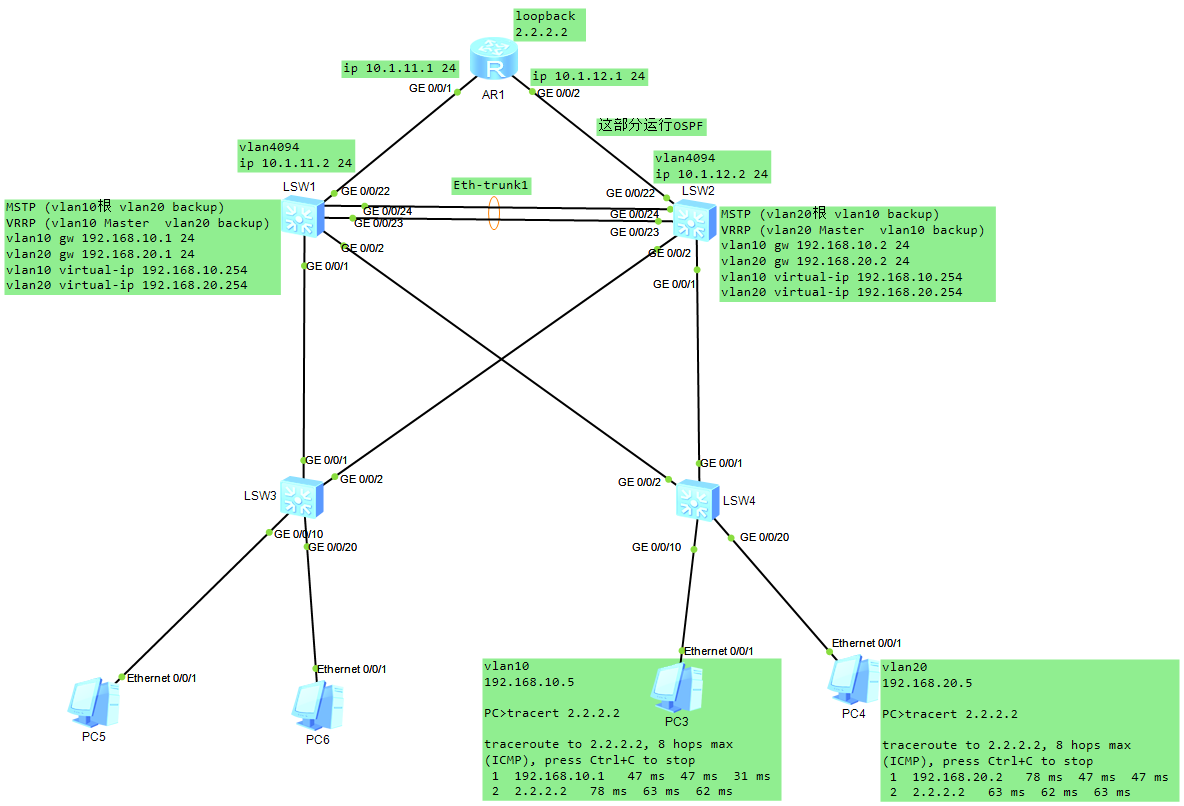
交换机与交换机之间的链路为trunk类型,放行vlan10 20
SW1配置:
[sw1]vlan batch 10 20    #创建vlan10 20

[sw1-Vlanif10]dis this
#
interface Vlanif10
 ip address 192.168.10.1 255.255.255.0        #配置物理网关地址
 vrrp vrid 1 virtual-ip 192.168.10.254        #配置vrrp组1  配置虚拟网关地址
 vrrp vrid 1 priority 120        #配置优先级为120,默认100数字越大越优先,使它成为vlan10的Master
 vrrp vrid 1 preempt-mode timer delay 20    #延迟20秒后抢占
 vrrp vrid 1 track interface GigabitEthernet0/0/3 reduced 30        #检测上联端口,如果断开优先级降低30(之后会作为backup)
#

[sw1-Vlanif20]dis this
#
interface Vlanif20
 ip address 192.168.20.1 255.255.255.0        #配置vlan20的物理网关
 vrrp vrid 2 virtual-ip 192.168.20.254        #配置vlan20的虚拟网关


MSTP配置
[sw1]stp mode mstp  #配置stp模式为mstp
[sw1]stp region-configuration  #进入stp配置模式
[sw1-mst-region]dis this
#
stp region-configuration
 region-name HW    #配置域名为HW
 revision-level 1    #配置版本等级为1(可选)
 instance 10 vlan 10  #配置vlan10 加入实例10
 instance 20 vlan 20  #配置vlan20 加入实例20
 active region-configuration
#

[sw1]stp instance 10 root primary     #配置实例10为根
[sw1]stp instance 20 root secondary     #配置实例20为备份根
SW2配置:
[sw2]vlan batch 10 20
[sw2-Vlanif10]dis this
#
interface Vlanif10
 ip address 192.168.10.2 255.255.255.0  #配置vlan10网关
 vrrp vrid 1 virtual-ip 192.168.10.254  #配置vrrp组1 配置虚拟网关和SW1一样
#

[sw2-Vlanif20]dis this
#
interface Vlanif20
 ip address 192.168.20.2 255.255.255.0  #配置vlan20网关
 vrrp vrid 2 virtual-ip 192.168.20.254  #配置vrrp组2 配置虚拟网关和SW1一样
 vrrp vrid 2 priority 120  #配置优先级为120,使vrrp2 成为vlan20的Master
 vrrp vrid 2 preempt-mode timer delay 20  #延迟20s后抢占
 vrrp vrid 2 track interface GigabitEthernet0/0/22 reduced 30  #配置上联链路检测,如果断开优先级减去30 使它成为backup

#


MSTP配置
[sw2]stp mode mstp  #配置stp模式为mstp
[sw2]stp region-configuration  #进入stp配置模式
[sw2-mst-region]dis this
#
stp region-configuration
 region-name HW    #配置域名为HW
 revision-level 1    #配置版本等级为1(可选)
 instance 10 vlan 10  #配置vlan10 加入实例10
 instance 20 vlan 20  #配置vlan20 加入实例20
 active region-configuration
#

[sw2]stp instance 20 root primary     #配置实例20为根
[sw2]stp instance 10 root secondary     #配置实例10为备份根
SW3配置:
[sw3]vlan batch 10 20
MSTP配置
[sw3]stp mode mstp  #配置stp模式为mstp
[sw3]stp region-configuration  #进入stp配置模式
[sw3-mst-region]dis this
#
stp region-configuration
 region-name HW    #配置域名为HW
 revision-level 1    #配置版本等级为1(可选)
 instance 10 vlan 10  #配置vlan10 加入实例10
 instance 20 vlan 20  #配置vlan20 加入实例20
 active region-configuration
#
SW4配置:
[sw4]vlan batch 10 20
MSTP配置
[sw4]stp mode mstp  #配置stp模式为mstp
[sw4]stp region-configuration  #进入stp配置模式
[sw4-mst-region]dis this
#
stp region-configuration
 region-name HW    #配置域名为HW
 revision-level 1    #配置版本等级为1(可选)
 instance 10 vlan 10  #配置vlan10 加入实例10
 instance 20 vlan 20  #配置vlan20 加入实例20
 active region-configuration
#
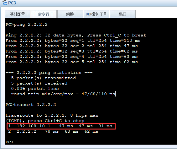
测试效果:
可以看出来PC3走的是 sw1的网关
PC4走的是SW2的网关

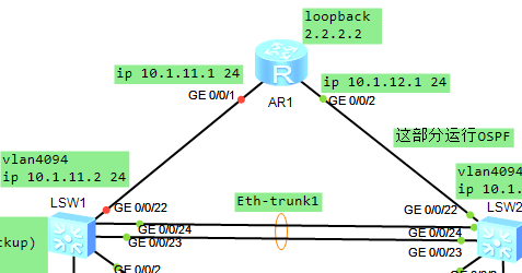
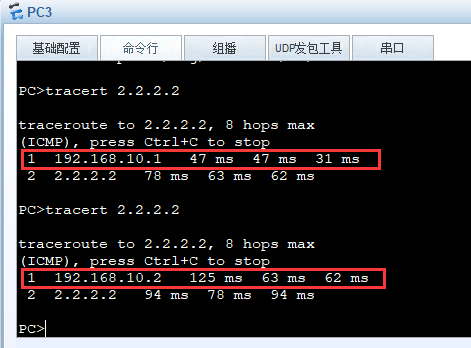
假设SW1的上联链路断开:
SW2接管了vlan10成为了Master
<sw2>dis vrrp
  Vlanif10 | Virtual Router 10
    State : Master    #sw2变成了vlan10的Master
    Virtual IP : 192.168.10.254
    Master IP : 192.168.10.2
    PriorityRun : 100
    PriorityConfig : 100
    MasterPriority : 100
    Preempt : YES   Delay Time : 0 s
    TimerRun : 1 s
    TimerConfig : 1 s
    Auth type : NONE
    Virtual MAC : 0000-5e00-010a
    Check TTL : YES
    Config type : normal-vrrp
    Create time : 2021-09-07 20:41:05 UTC-08:00
    Last change time : 2021-09-08 10:39:48 UTC-08:00
可以看出来PC3的数据从SW1切换到了SW2上
End