


Vivado简单调试技能
1.关于VIO核的使用
首先配置VIO核:

配置输入输出口的数量5,5

配置输入口的位宽

配置输出口位宽和初始值。
例化与使用:

vio_0 U1 (
  .clk(clk_27M),                // input wire clk
  .probe_in0(),    // input wire [0 : 0] probe_in0
  .probe_in1(),    // input wire [0 : 0] probe_in1
  .probe_in2(),    // input wire [0 : 0] probe_in2
  .probe_in3(),    // input wire [0 : 0] probe_in3
  .probe_in4(),    // input wire [0 : 0] probe_in4
  .probe_out0(),  // output wire [0 : 0] probe_out0
  .probe_out1(qpllreset),  // output wire [0 : 0] probe_out1
  .probe_out2(),  // output wire [0 : 0] probe_out2
  .probe_out3(),  // output wire [0 : 0] probe_out3
  .probe_out4()  // output wire [0 : 0] probe_out4
);
一定要注意的是,准确给定这个核的时钟,probe_in端口目前还不知道怎么用,只使用了probe_out端口。使用场景就是让这个核输出某个数值到相关的信号线,比如:.probe_out1(qpllreset), // output wire [0 : 0] probe_out1;可以在调试阶段控制这个核输出0或者1给qpllreset信号,由此我们可以手动对QPLL进行复位控制了。
2.ILA核的使用
配置ILA核:

配置probes的个数,和数据采样的深度。

分别配置每个probe的位宽。
例化与使用ILA核:
ila_0 U5 (
    .clk(drpclk), // input wire clk
    .probe0(current_state_W), // input wire [0:0]  probe0
    .probe1(next_state_W), // input wire [0:0]  probe1
    .probe2(timeout_cntr_W),
    .probe3(clear_timeout_cntr_W), // input wire [0:0]  probe3
    .probe4(plllock_timeout_W), // input wire [0:0]  probe4
    .probe5(reset_timeout_W), // input wire [0:0]  probe5
    .probe6(init_period_done_W), // input wire [0:0]  probe6
    .probe7(refclk_stable_ss_W), // input wire [2:0]  probe7
    .probe8(refclk_stable_s), // input wire [0:0]  probe8
    .probe9(pll_lock_ss_W), // input wire [2:0]  probe9
    .probe10(pll_lock_s), // input wire [0:0]  probe10
    .probe11(rxresetdone_ss_W), // input wire [2:0]  probe11
    .probe12(assert_pll_reset_W), // input wire [0:0]  probe12
    .probe13(assert_gt_reset_W), // input wire [0:0]  probe13
    .probe14(assert_done_W), // input wire [0:0]  probe14
    .probe15(assert_fail_W), // input wire [0:0]  probe15
    .probe16(assert_drp_req_W), // input wire [0:0]  probe16
    .probe17(assert_drp_busy_out_W), // input wire [0:0]  probe17
    .probe18(inc_retry_cntr_W), // input wire [0:0]  probe18
    .probe19(clear_retry_cntr_W), // input wire [0:0]  probe19
    .probe20(max_retries), // input wire [0:0]  probe20
    .probe21(rxresetdone_s) // input wire [0:0]  probe21
);
同样,也需要给这个核输入时钟,probe()端口需要接入wire类型的信号,在调试的过程中我们经常需要抓取reg类型的信号进行分析,因此可以这样处理,将reg型转为wire型:
reg                                 assert_pll_reset;
wire assert_pll_reset_W;
assign assert_pll_reset_W = assert_pll_reset;

reg                                 assert_gt_reset;
wire assert_gt_reset_W;
assign assert_gt_reset_W = assert_gt_reset;

reg                                 assert_done;
wire assert_done_W;
assign assert_done_W = assert_done;

reg                                 assert_fail;
wire assert_fail_W;
assign assert_fail_W = assert_fail;

reg                                 assert_drp_req;
wire assert_drp_req_W;
assign assert_drp_req_W = assert_drp_req;
烧写完程序之后,就可以抓这些信号的波形,得到的波形图如下:

3.关于set up debug的使用:
Set up debug算是一种自动添加ILA核的方法。在下面的对话框中加入我们要查看的信号,然后重新进行综合布局布线生成bit文件,烧写程序完成后出现波形界面。
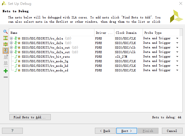
注意其中信号的时钟域不同,生成的ILA核就不同:
手动添加的ILA核

时钟域为clk_27M

时钟域为:SDI0/SDI/CLK

时钟域为:SDI0/SDI/CLK


【推荐】国内首个AI IDE,深度理解中文开发场景,立即下载体验Trae
【推荐】编程新体验,更懂你的AI,立即体验豆包MarsCode编程助手
【推荐】抖音旗下AI助手豆包,你的智能百科全书,全免费不限次数
【推荐】轻量又高性能的 SSH 工具 IShell:AI 加持,快人一步
· 10年+ .NET Coder 心语,封装的思维:从隐藏、稳定开始理解其本质意义
· .NET Core 中如何实现缓存的预热?
· 从 HTTP 原因短语缺失研究 HTTP/2 和 HTTP/3 的设计差异
· AI与.NET技术实操系列:向量存储与相似性搜索在 .NET 中的实现
· 基于Microsoft.Extensions.AI核心库实现RAG应用
· 10年+ .NET Coder 心语 ── 封装的思维:从隐藏、稳定开始理解其本质意义
· 地球OL攻略 —— 某应届生求职总结
· 提示词工程——AI应用必不可少的技术
· Open-Sora 2.0 重磅开源!
· 周边上新:园子的第一款马克杯温暖上架