CS3342 Lecture 4
UML - Class diagram
A class diagram is used to visualize object-oriented classes and their relationships in our system.

Class Linkages – 3 Types
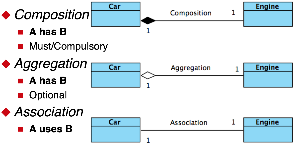
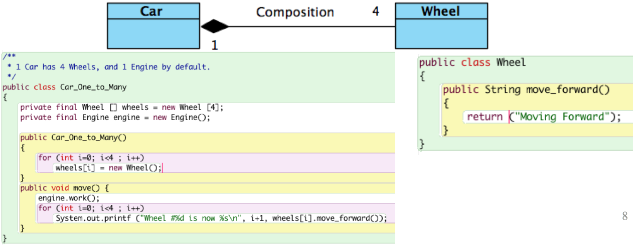
Composition - <black diamond>
A has B (B Must be included)
Implementation: Class_A contains a fixed local variable links to Class_B
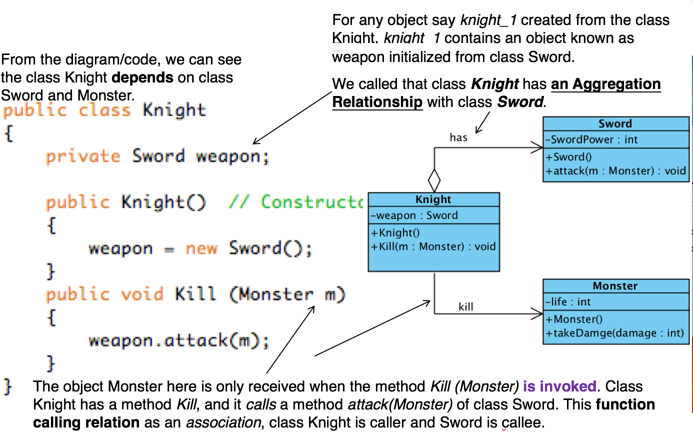
Aggregation - <white diamond>
A has B (B is Optional, can be included later)
Implementation: Class_A contains a changeable local variable links to Class_B
Association
A uses B (can define B at runtime, more dynamic)
Class_A DO NOT contain a local variable links to Class_B
Class_A uses Class_B as (input/output) Parameter directly.
Example:
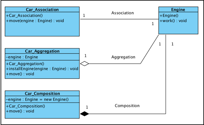 in VP
in VP
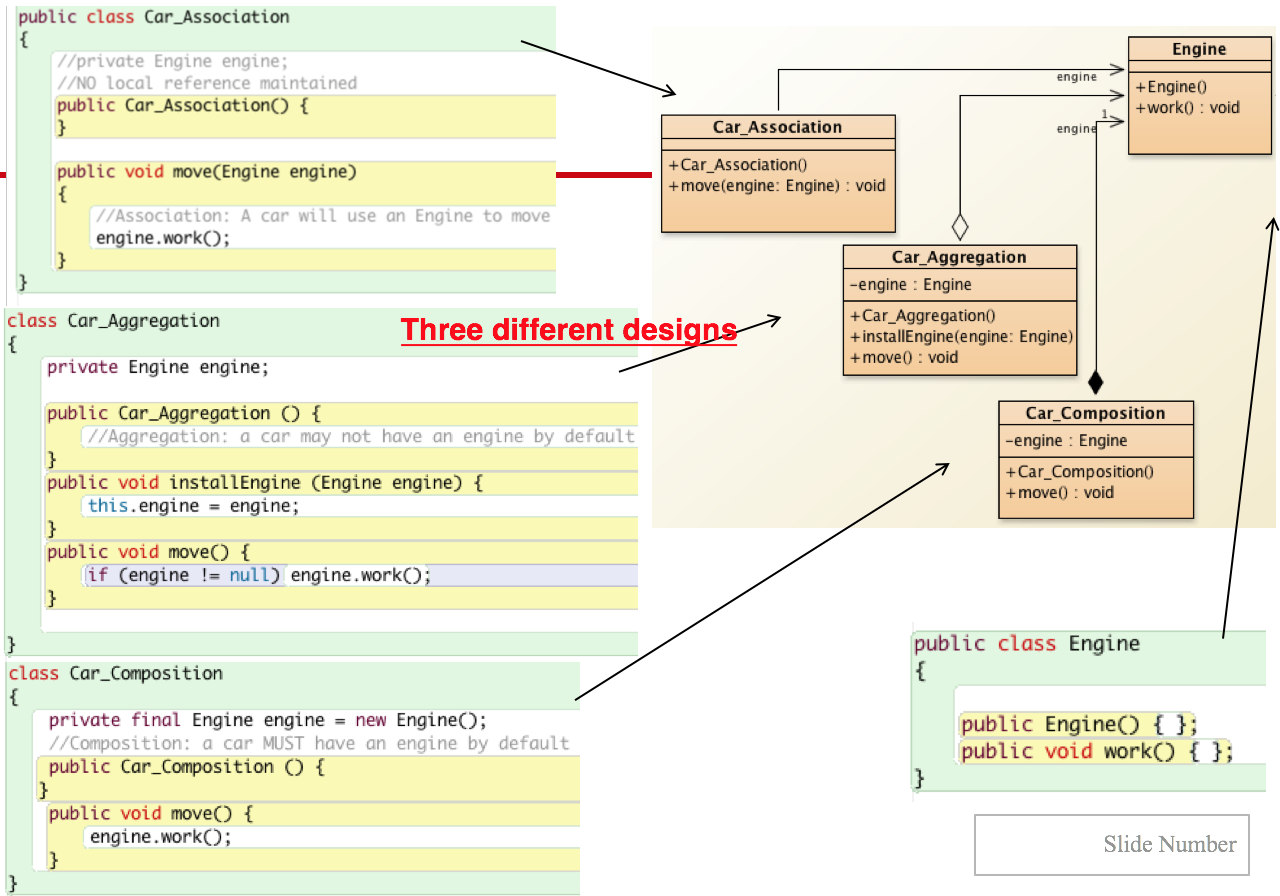 in BlueJ
Association &Multiplicity
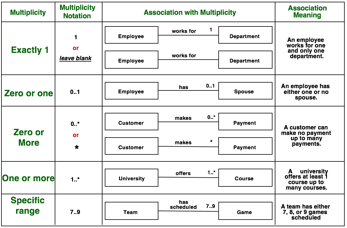
Example1:
A (1) Car has (Must) four (4) Wheels. (Contains 4x “Wheel” object instances) - Use a container such as Array, ArrayList.. etc
Example2:
UML - Use Case diagram
Use Cases – visualize functional interactions
Typically, a use case is a contract of an interaction between the system and an actor.
The Actor can be a human or an external system / machine.
A full use-case model comprise of:
–A Use Case Diagram, describing relations between use-cases (system tasks, roles) and actors (external parties).
–Use Case Specifications (usually one per each use case) - Documents describe the use case in details
Use Cases as Means of Communication in real world
The use case should stimulate a discussion about what the system should do, mainly with people who are outside of the development team.
Use Case Diagram Objective
1. Create a semi-formal model of the functional requirements (What the system does…)
2. Analyze and define:
–Scope (What are the main functions?)
–External parties (who will interact with the system?)
–External interfaces (how they are related?)
–Scenarios and reactions (One Big Picture)
Steps to Build an Use-Case Model
- Choose the system boundary – what are you modeling? System? Business organization?
- Identify the primary actors – they have user goals fulfilled by using the services of the system
- For each primary actor, identify their user goals – define what they want to do with the system. Describe their goals at the correct level
- Define use cases that satisfy user goals. Name each according to its goal. [You may find out other actors, which we call secondary actors of that particular use case.]
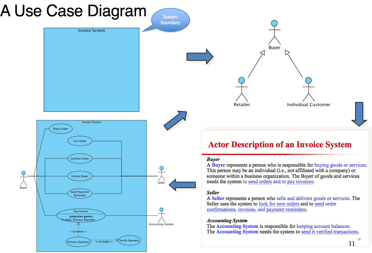
Find Actors
External objects(Must be external to the system) that produce/consume data(Must serve as sources and destinations for data):
- human/system outside the system that interacts with the system
- provides input to or takes output from the system
- a role the user can play multiple roles possible
Eg: Humans, Machines, External Systems, Sensors, Organization Units...
Note: Database and Printer are NOT actors
Primary actor - interacts directly with the system
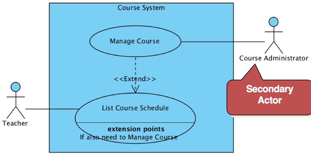
Secondary actor - interacts indirectly with the system or support the use case to complete a use case for the primary actor
Three Basic Types of Relationship in Use Case Model
Association
Instances of the actor and instances of the use case communicate with each other
The only relationship between actors and use cases
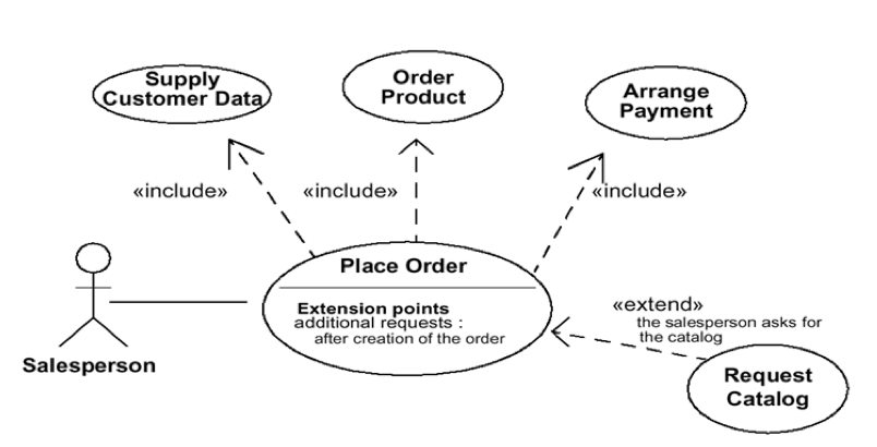
<<Include>> Relationship
Allow one to express commonality between several different use cases.
Can be included in other use cases
Even very different use cases can share sequence of actions.
Enable you to avoid repeating details in multiple use cases.
Shows the performing of a lower-level task with a lower-level goal.
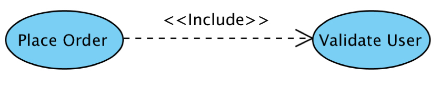 "place order" includes "validate user"
<<Extend>> Relationship
Use it to show optional behavior explicit or to handle exception scenarios
Keep the description of the basic use case simple.
The base use case can incorporate another use case at certain points, called extension points. (IF… THEN… )
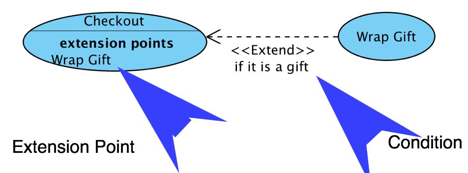 In "Checkout" use case, IF "the item is a gift", THEN perform "Wrap Gift".
Example:
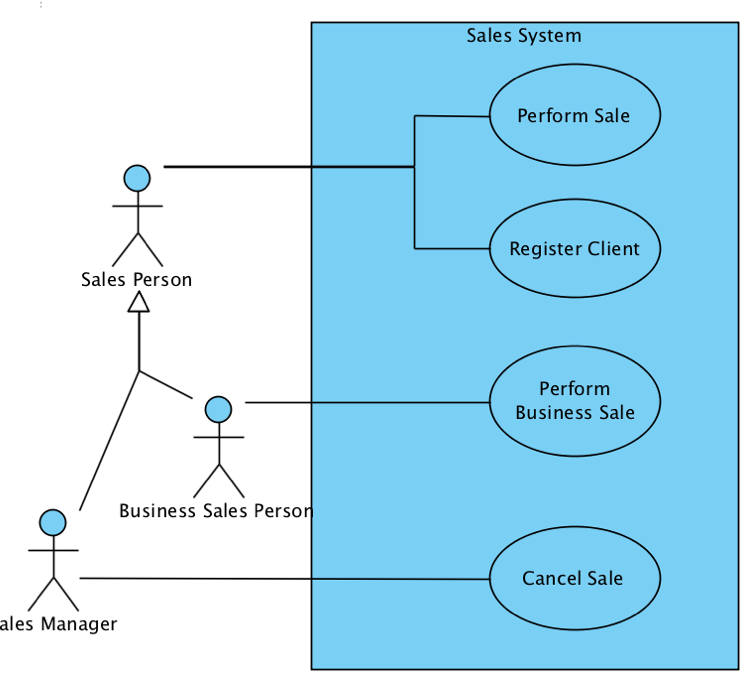
Generalization(Inheritance)
A generalization from use case A to use case B indicates that A inherits B.
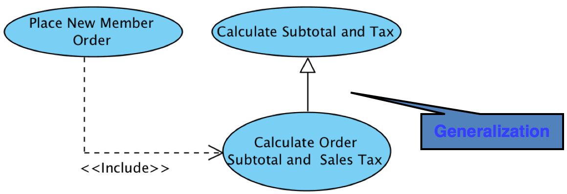
Actors can also be generalized
Guidelines for Effective Use Cases
Number Limit:
The diagram should have between 3 to 10 base use-case. No more than 15 use cases (base + included + extending).
Abstraction:
All use-cases should be in similar abstraction levels.
Size:
Use cases should be described in half a page or more.
Weak dependency:
If the dependency between two parts of a use-case is weak, they should be splitted.
Factor out common usages that are required by multiple use cases:
If the usage is required use <<include>>
If the base use case is complete and the usage may be optional or conditional consider use <<extend>>
A use case diagram should:
contain only use cases at the same level of abstraction
include only actors which are required
Writing Use Cases
.....

 浙公网安备 33010602011771号