【计算机视觉】相机畸变校正(Lens Distortion Correction)
前言
相机作为视觉传感器,是机器人、监视、太空探索、社交媒体、工业自动化,甚至娱乐行业等多个领域不可或缺的一部分。对于许多应用来说,知道相机的参数是必不可少的,以便有效地将其用作视觉传感器。在这篇文章中,便会介绍相机校准的步骤,以及如何来校正失真的图像。
什么是相机校准?
对摄像机参数进行估计的过程称为摄像机标定。这意味着我们拥有关于摄像机的所有信息(参数或系数),以确定真实世界中的3D点与校准后的摄像机捕捉到的图像中相应的2D投影(像素)之间的精确关系。
正如文章中所解释的,要找到一个3D点在图像平面上的投影,我们首先需要使用外部参数(Rotation R和Translation T)将这个点从世界坐标系转换到摄像机坐标系。接下来,利用相机的内在参数,我们将点投影到图像平面上。
三维点![]() 在世界坐标中的投影(u, v)与图像坐标中的投影(u, v)相关联的方程如下所示:
在世界坐标中的投影(u, v)与图像坐标中的投影(u, v)相关联的方程如下所示:
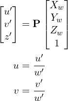
其中,P是一个3×4投影矩阵,由两部分组成:包含内部参数的内参矩阵(K)和由3×3旋转矩阵R和3×1平移向量t组合而成的外参矩阵。
![]()
如前所述,本征矩阵K是上三角矩阵:

其中,![]() 是x和y的焦距(它们通常是相同的)。
是x和y的焦距(它们通常是相同的)。
 是光学中心在接收平面中的x坐标和y坐标。使用图像的中心通常是一个足够好的近似。
 是坐标轴之间的斜度。通常是0。
相机标定的目标
校准过程的目标是使用一组已知的3D点![]() 及其对应的图像坐标(u, v)找到3×3矩阵K、3×3旋转矩阵R和3×1平移向量t。当我们得到相机的内参数和外参数的值时,我们就说相机被标定了。
及其对应的图像坐标(u, v)找到3×3矩阵K、3×3旋转矩阵R和3×1平移向量t。当我们得到相机的内参数和外参数的值时,我们就说相机被标定了。
总之,摄像机标定算法有以下输入和输出:
- 输入:已知二维图像坐标和三维世界坐标的点的图像集合。
- 输出:3x3的相机内参矩阵,每张图像的旋转和平移。
注意:在OpenCV中,相机内参矩阵不包含倾斜参数。这个矩阵就是这种形式 
不同类型的相机标定方法
以下是几种主要的相机标定方法:
- 校准模式:当我们完全控制成像过程时,进行校准的最佳方式是从不同的视角捕捉一个物体或已知尺寸的模式的几张图像。我们将在这篇文章中学习的基于棋盘的方法属于这一类。我们也可以用已知尺寸的圆形图案来代替棋盘图案。
- 几何线索:有时我们在场景中会有其他几何线索,如直线和消失点,这些线索可以用于校准。
- 基于深度学习的:当我们对成像设置几乎没有控制时(例如,我们只有场景的一张图像),仍然可以使用基于深度学习的方法获得相机的校准信息。
相机标定的步骤
用以下流程图来描述相机标定的步骤:
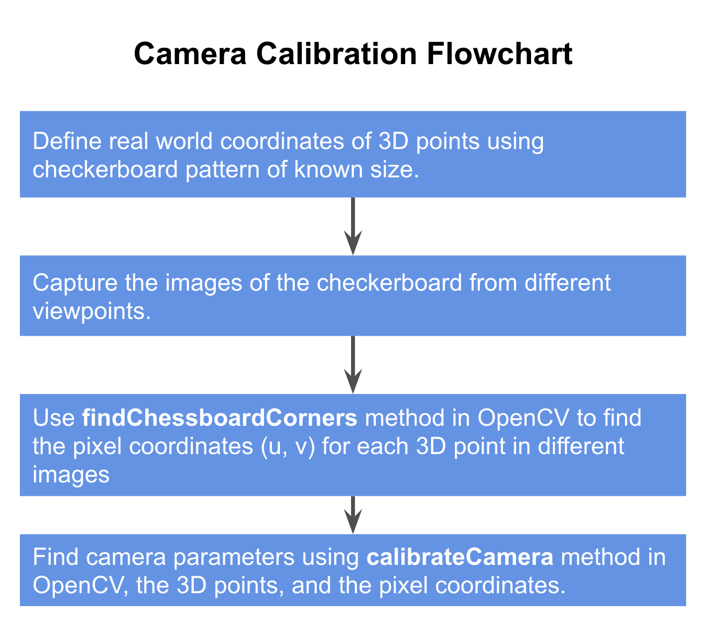
具体细节此处不再详述,参考:https://learnopencv.com/camera-calibration-using-opencv/
->相机标定的python实现:
1 2 3 4 5 6 7 8 9 10 11 12 13 14 15 16 17 18 19 20 21 22 23 24 25 26 27 28 29 30 31 32 33 34 35 36 37 38 39 40 41 42 43 44 45 46 47 48 49 50 51 52 53 54 55 56 57 58 59 60 61 62 63 64 65 66 67 68 69 | #!/usr/bin/env pythonimport cv2import numpy as npimport osimport glob# Defining the dimensions of checkerboardCHECKERBOARD = (6,9)criteria = (cv2.TERM_CRITERIA_EPS + cv2.TERM_CRITERIA_MAX_ITER, 30, 0.001)# Creating vector to store vectors of 3D points for each checkerboard imageobjpoints = []# Creating vector to store vectors of 2D points for each checkerboard imageimgpoints = [] # Defining the world coordinates for 3D pointsobjp = np.zeros((1, CHECKERBOARD[0] * CHECKERBOARD[1], 3), np.float32)objp[0,:,:2] = np.mgrid[0:CHECKERBOARD[0], 0:CHECKERBOARD[1]].T.reshape(-1, 2)prev_img_shape = None# Extracting path of individual image stored in a given directoryimages = glob.glob('./images/*.jpg')for fname in images: img = cv2.imread(fname) gray = cv2.cvtColor(img,cv2.COLOR_BGR2GRAY) # Find the chess board corners # If desired number of corners are found in the image then ret = true ret, corners = cv2.findChessboardCorners(gray, CHECKERBOARD, cv2.CALIB_CB_ADAPTIVE_THRESH + cv2.CALIB_CB_FAST_CHECK + cv2.CALIB_CB_NORMALIZE_IMAGE) """ If desired number of corner are detected, we refine the pixel coordinates and display them on the images of checker board """ if ret == True: objpoints.append(objp) # refining pixel coordinates for given 2d points. corners2 = cv2.cornerSubPix(gray, corners, (11,11),(-1,-1), criteria) imgpoints.append(corners2) # Draw and display the corners img = cv2.drawChessboardCorners(img, CHECKERBOARD, corners2, ret) cv2.imshow('img',img) cv2.waitKey(0)cv2.destroyAllWindows()h,w = img.shape[:2]"""Performing camera calibration by passing the value of known 3D points (objpoints)and corresponding pixel coordinates of the detected corners (imgpoints)"""ret, mtx, dist, rvecs, tvecs = cv2.calibrateCamera(objpoints, imgpoints, gray.shape[::-1], None, None)print("Camera matrix : \n")print(mtx)print("dist : \n")print(dist)print("rvecs : \n")print(rvecs)print("tvecs : \n")print(tvecs) |
->相机标定的C++实现:
1 2 3 4 5 6 7 8 9 10 11 12 13 14 15 16 17 18 19 20 21 22 23 24 25 26 27 28 29 30 31 32 33 34 35 36 37 38 39 40 41 42 43 44 45 46 47 48 49 50 51 52 53 54 55 56 57 58 59 60 61 62 63 64 65 66 67 68 69 70 71 72 73 74 75 76 77 78 79 80 81 82 83 84 85 86 87 88 89 90 91 | #include <opencv2/opencv.hpp>#include <opencv2/calib3d/calib3d.hpp>#include <opencv2/highgui/highgui.hpp>#include <opencv2/imgproc/imgproc.hpp>#include <stdio.h>#include <iostream>// Defining the dimensions of checkerboardint CHECKERBOARD[2]{6,9}; int main(){ // Creating vector to store vectors of 3D points for each checkerboard image std::vector<std::vector<cv::Point3f> > objpoints; // Creating vector to store vectors of 2D points for each checkerboard image std::vector<std::vector<cv::Point2f> > imgpoints; // Defining the world coordinates for 3D points std::vector<cv::Point3f> objp; for(int i{0}; i<CHECKERBOARD[1]; i++) { for(int j{0}; j<CHECKERBOARD[0]; j++) objp.push_back(cv::Point3f(j,i,0)); } // Extracting path of individual image stored in a given directory std::vector<cv::String> images; // Path of the folder containing checkerboard images std::string path = "./images/*.jpg"; cv::glob(path, images); cv::Mat frame, gray; // vector to store the pixel coordinates of detected checker board corners std::vector<cv::Point2f> corner_pts; bool success; // Looping over all the images in the directory for(int i{0}; i<images.size(); i++) { frame = cv::imread(images[i]); cv::cvtColor(frame,gray,cv::COLOR_BGR2GRAY); // Finding checker board corners // If desired number of corners are found in the image then success = true success = cv::findChessboardCorners(gray, cv::Size(CHECKERBOARD[0], CHECKERBOARD[1]), corner_pts, CV_CALIB_CB_ADAPTIVE_THRESH | CV_CALIB_CB_FAST_CHECK | CV_CALIB_CB_NORMALIZE_IMAGE); /* * If desired number of corner are detected, * we refine the pixel coordinates and display * them on the images of checker board */ if(success) { cv::TermCriteria criteria(CV_TERMCRIT_EPS | CV_TERMCRIT_ITER, 30, 0.001); // refining pixel coordinates for given 2d points. cv::cornerSubPix(gray,corner_pts,cv::Size(11,11), cv::Size(-1,-1),criteria); // Displaying the detected corner points on the checker board cv::drawChessboardCorners(frame, cv::Size(CHECKERBOARD[0], CHECKERBOARD[1]), corner_pts, success); objpoints.push_back(objp); imgpoints.push_back(corner_pts); } cv::imshow("Image",frame); cv::waitKey(0); } cv::destroyAllWindows(); cv::Mat cameraMatrix,distCoeffs,R,T; /* * Performing camera calibration by * passing the value of known 3D points (objpoints) * and corresponding pixel coordinates of the * detected corners (imgpoints) */ cv::calibrateCamera(objpoints, imgpoints, cv::Size(gray.rows,gray.cols), cameraMatrix, distCoeffs, R, T); std::cout << "cameraMatrix : " << cameraMatrix << std::endl; std::cout << "distCoeffs : " << distCoeffs << std::endl; std::cout << "Rotation vector : " << R << std::endl; std::cout << "Translation vector : " << T << std::endl; return 0;} |
-----------------------------------------------------
上述我们了解了图像形成的几何知识,并知道了3D中的一个点如何投影到相机的图像平面,我们使用的模型是基于针孔相机模型。任何真实世界的相机的图像形成模型都涉及到一个镜头。
为了产生清晰和清晰的图像,针孔相机的孔径(孔)直径应该尽可能小。 如果我们增加光圈的大小,我们知道从物体的多个点发出的光线会照射到屏幕的同一部分,产生模糊的图像。
另一方面,如果我们使光圈尺寸小,只有少量的光子击中图像传感器。 那么,图像是黑暗和嘈杂的。
因此,针孔相机的光圈越小,图像越清晰,但同时,它的光线也越暗,噪音也越大。
另一方面,孔径越大,图像传感器接收到的光子就越多(因此接收到的信号也就越多)。 这将导致只有少量噪声的明亮图像。
失真效应的主要类型及其原因
通过使用透镜,我们得到了更好的质量的图像,但透镜引入了一些失真的效果。有两种主要的失真效果:
- 径向畸变(Radial distortion):这种畸变通常是由于光的不均匀弯曲造成的。靠近透镜边缘的光线比靠近透镜中心的光线更容易弯曲。由于径向失真,现实世界中的直线在图像中显得弯曲。光线在击中图像传感器之前,会从理想位置向内或向外进行放射状位移。径向畸变效应有两种类型:(1)桶形畸变效应(Barrel distortion effect),对应负的径向位移;(2)枕形畸变效应(Pincushion distortion effect),对应于一个正的径向位移。
- 切向畸变(Tangential distortion):这通常发生在图像屏幕或传感器与镜头成一定角度时。因此图像似乎是倾斜和拉伸的。
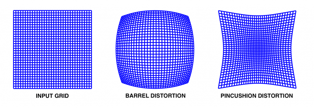
图1:方形网格上描述径向畸变和枕形畸变影响的图像。
基于[1]的畸变,根据畸变源的不同可分为三种:径向畸变、偏心畸变和薄棱镜畸变。偏心和薄棱镜畸变同时具有径向畸变和切向畸变效应。
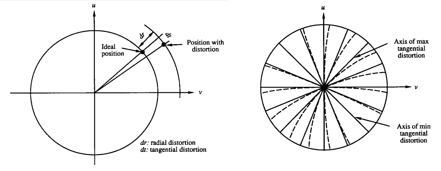
图2:来自[1]的图表解释了切向失真的影响,实线表示没有失真的情况,虚线表示切向失真(右)和(左)切向和径向失真如何从理想位置移动像素。
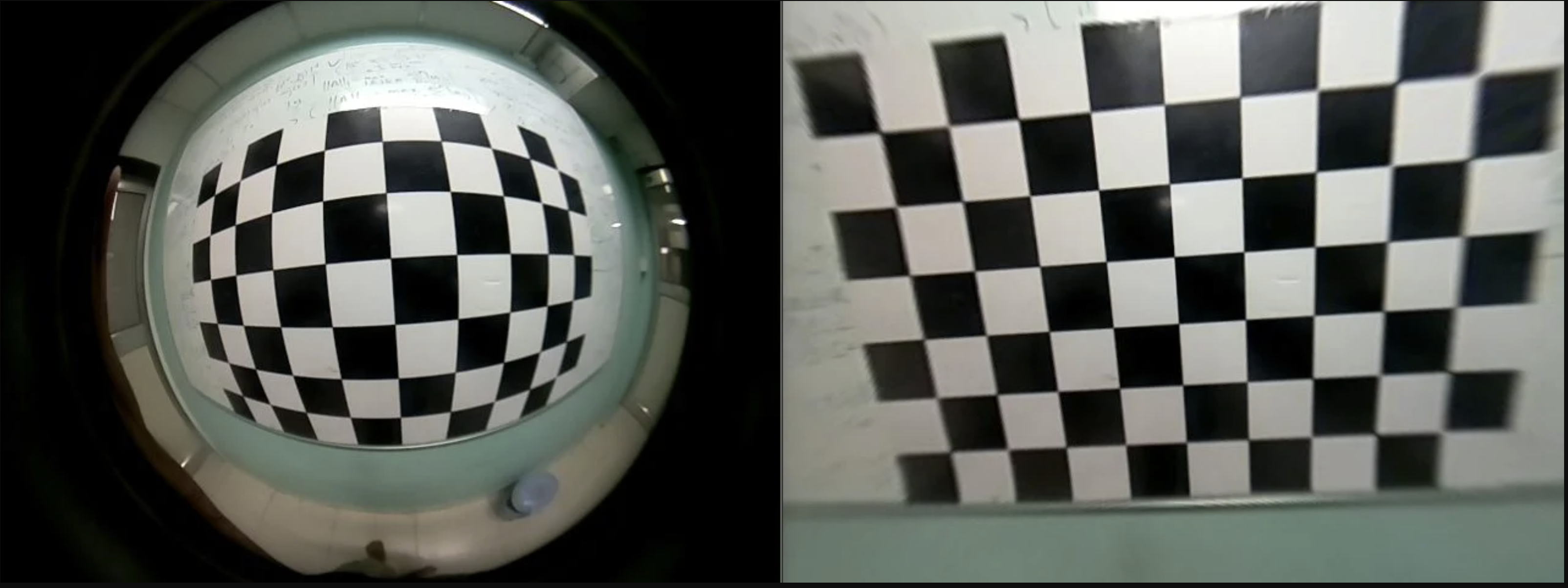
现在我们对透镜产生的畸变效果有了更好的了解,但是畸变的图像是什么样的呢?我们需要担心镜头带来的失真吗?如果是,为什么?我们该如何应对?
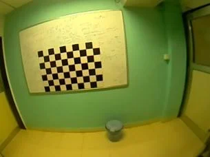
图3:显示失真效果的图片。注意墙壁和门的边缘是如何由于变形而弯曲的。
上图是一个透镜可以引入畸变效应的例子。你可以把图3和图1联系起来,说它是一个桶形畸变效应,一种径向畸变效应。现在,如果让你找出正确的门的高度,你会考虑哪两点?当您在进行SLAM或使用具有高失真效果的相机进行一些增强现实应用时,事情会变得更加困难。
数学上表征镜头畸变
当我们试图从图像中估计真实世界的3D点时,我们需要考虑这些失真效应。
我们基于镜头特性对畸变效应进行数学建模,并将其与前面解释的针孔相机模型结合起来。因此,除了前面讨论的内在参数和外在参数外,我们还有畸变系数(在数学上表示透镜畸变),作为额外的内在参数。为了在我们的相机模型中考虑这些畸变,我们对针孔相机模型进行如下修改:
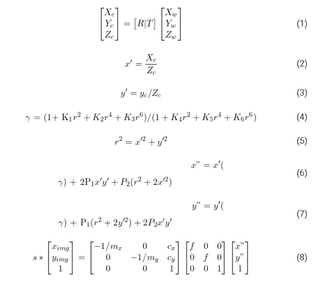
由calibrateCamera方法返回的distCoeffs矩阵给出了K_1到K_6的值,表示径向失真,P_1, P_2表示切向失真。我们知道,上述表示透镜畸变的数学模型包括了所有类型的畸变,径向畸变、偏心畸变和薄棱镜畸变,因此K_1 ~ K_6系数表示净径向畸变,P_1和P_2表示净切向畸变。
使用OpenCV消除失真
去除透镜畸变主要有三个步骤:
- 对摄像机进行标定,得到摄像机固有参数。这就是我们在本系列的前一篇文章中所做的。本征参数还包括相机畸变参数。
- 改进相机矩阵以控制不失真图像中不需要的像素的百分比。
- 利用改进的相机矩阵使图像不失真。
第二步是使用getOptimalNewCameraMatrix()方法执行的。 这个精致的矩阵意味着什么?我们为什么需要它? 参考下面的图片,在右边的图片中,我们看到一些靠近边缘的黑色像素。 这是由于图像不变形造成的。 有时这些黑色像素在最终未失真的图像中是不理想的。 因此,getOptimalNewCameraMatrix()方法返回一个精细的相机矩阵和ROI(感兴趣的区域),可用于裁剪图像,以便排除所有黑色像素。 要消除的多余像素的百分比由参数alpha控制,alpha作为参数传递给getOptimalNewCameraMatrix()方法。
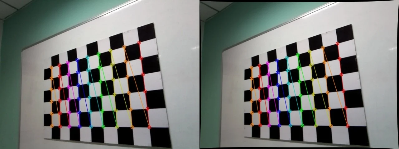
未失真的图像,左图alpha=0,右图alpha=1。
要注意,有时在高径向扭曲的情况下,使用alpha=0的getOptimalNewCameraMatrix()生成一个空白的图像。 这种情况通常会发生,因为这种方法对边缘的失真估计很差。 在这种情况下,你需要重新校准相机,并确保更多的图像拍摄以不同的视角靠近图像边界。 这样在图像边缘附近就有了更多的样本来估计失真,从而提高了估计精度。
->python实现:
1 2 3 4 5 6 7 8 9 10 11 12 13 14 | # Refining the camera matrix using parameters obtained by calibrationnewcameramtx, roi = cv2.getOptimalNewCameraMatrix(mtx, dist, (w,h), 1, (w,h))# Method 1 to undistort the imagedst = cv2.undistort(img, mtx, dist, None, newcameramtx)# Method 2 to undistort the imagemapx,mapy=cv2.initUndistortRectifyMap(mtx,dist,None,newcameramtx,(w,h),5)dst = cv2.remap(img,mapx,mapy,cv2.INTER_LINEAR)# Displaying the undistorted imagecv2.imshow("undistorted image",dst)cv2.waitKey(0) |
->C++实现:
1 2 3 4 5 6 7 8 9 10 11 12 13 14 15 16 17 | cv::Mat dst, map1, map2,new_camera_matrix;cv::Size imageSize(cv::Size(image.cols,image.rows));// Refining the camera matrix using parameters obtained by calibrationnew_camera_matrix = cv::getOptimalNewCameraMatrix(cameraMatrix, distCoeffs, imageSize, 1, imageSize, 0);// Method 1 to undistort the imagecv::undistort( frame, dst, new_camera_matrix, distCoeffs, new_camera_matrix );// Method 2 to undistort the imagecv::initUndistortRectifyMap(cameraMatrix, distCoeffs, cv::Mat(),cv::getOptimalNewCameraMatrix(cameraMatrix, distCoeffs, imageSize, 1, imageSize, 0),imageSize, CV_16SC2, map1, map2);cv::remap(frame, dst, map1, map2, cv::INTER_LINEAR);//Displaying the undistorted imagecv::imshow("undistorted image",dst);cv::waitKey(0);; |
参考:
[1] J. Weng, P. Cohen, and M. Herniou. Camera calibration with distortion models and accuracy
evaluation. IEEE Transactions on Pattern Analysis and Machine Intelligence, 14(10):965–980,
Oct. 1992.
[2] OpenCV documentation for camera calibration.


【推荐】国内首个AI IDE,深度理解中文开发场景,立即下载体验Trae
【推荐】编程新体验,更懂你的AI,立即体验豆包MarsCode编程助手
【推荐】抖音旗下AI助手豆包,你的智能百科全书,全免费不限次数
【推荐】轻量又高性能的 SSH 工具 IShell:AI 加持,快人一步
· 被坑几百块钱后,我竟然真的恢复了删除的微信聊天记录!
· 没有Manus邀请码?试试免邀请码的MGX或者开源的OpenManus吧
· 【自荐】一款简洁、开源的在线白板工具 Drawnix
· 园子的第一款AI主题卫衣上架——"HELLO! HOW CAN I ASSIST YOU TODAY
· Docker 太简单,K8s 太复杂?w7panel 让容器管理更轻松!