HDLbits day6
2、Multiplexers
2.1、2-to-1 multiplexer
创建一位宽的 2 对 1 多路复用器。当 sel=0 时,选择 a。当 sel=1 时,选择 b。
module top_module(
    input a, b, sel,
    output out );

    assign out=sel?b:a;
endmodule
2.2、2-to-1 bus multiplexer
创建一个 100 位宽的 2 对 1 多路复用器。当 sel=0 时,选择 a。当 sel=1 时,选择 b。
module top_module(
    input [99:0] a, b,
    input sel,
    output [99:0] out );

    assign out=sel?b:a;
endmodule
2.3、9-to-1 multiplexer
创建一个 16 位宽的 9 对 1 多路复用器。sel=0 选择 a,sel=1 选择 b,等等。对于未使用的情况(sel=9 到 15),将所有输出位设置为“1”。
module top_module(
    input [15:0] a, b, c, d, e, f, g, h, i,
    input [3:0] sel,
    output [15:0] out );

    always@(*)
        begin
            case(sel)
                4'b0000:out=a;
                4'b0001:out=b;
                4'b0010:out=c;
                4'b0011:out=d;
                4'b0100:out=e;
                4'b0101:out=f;
                4'b0110:out=g;
                4'b0111:out=h;
                4'b1000:out=i;
                default:out={16{1'b1}};
            endcase
        end

endmodule
2.4、256-to-1 multiplexer
创建一个 1 位宽、256 对 1 的多路复用器。256 个输入全部打包成一个 256 位输入向量。sel=0 应该选择in[0], sel=1 选择[1]中的位, sel=2 选择[2]中的位,等等。
module top_module(
    input [255:0] in,
    input [7:0] sel,
    output out );
//用if  else语句会创建闩锁
    assign out=in[sel];
endmodule
2.5、256-to-1 4-bit multiplexer
创建一个 4 位宽、256 对 1 的多路复用器。256 个 4 位输入全部打包成一个 1024 位输入向量。sel=0 应该选择[3:0]中的位, sel=1 选择[7:4]中的位, sel=2 选择[11:8]中的位等。
注释部分代码的报错:Error (10734): Verilog HDL error at top_module.v(10): sel is not a constant
冒号“:”操作符:A[a : b]的含义理解为vectorA中选择位的范围,目前其中a和b只能是常数,而不能是变量。此处应该区分动态数组。
所以,应该将in[(sel*4)+3:sel*4]中的四个bit,用拼接符{}包括起来,{in[sel*4+3], in[sel*4+2], in[sel*4+1], in[sel*4+0]} 组成新的位宽为4的向量后再赋值给out。
module top_module(
    input [1023:0] in,
    input [7:0] sel,
    output [3:0] out );

    //assign out=in[3+4*sel:4*sel];

    assign out={in[3+4*sel],in[2+4*sel],in[1+4*sel],in[4*sel]};
endmodule
3、 Arithmetic Circuits
3.1、Half adder
创建一个半加法器。半加器将两位相加(没有进位)并产生和和进位。
| a | b | sum | sout |
| 0 | 0 | 0 | 0 |
| 0 | 1 | 1 | 0 |
| 1 | 0 | 1 | 0 |
| 1 | 1 | 0 | 1 |
module top_module(
    input a, b,
    output cout, sum );

    //assign {cout,sum}=a+b;

    assign cout=a&b;
    assign sum=a^b;
endmodule
3.2、Full adder
创建一个全加器。全加器将三位相加(包括进位)并产生和和进位。
| a | b | cin | sum | cout |
| 0 | 0 | 0 | 0 | 0 |
| 0 | 0 | 1 | 1 | 0 |
| 0 | 1 | 0 | 1 | 0 |
| 0 | 1 | 1 | 0 | 1 |
| 1 | 0 | 0 | 1 | 0 |
| 1 | 0 | 1 | 0 | 1 |
| 1 | 1 | 0 | 0 | 1 |
| 1 | 1 | 1 | 1 | 1 |
module top_module(
    input a, b, cin,
    output cout, sum );

    //assign {cout,sum}=a+b+cin;

    assign sum=(~a)&(~b)&cin|(~a)&b&(~cin)|a&(~b)&(~cin)|a&b&cin;
    assign cout=a&b|a&cin|b&cin;
endmodule
3.3、3-bit binary adder
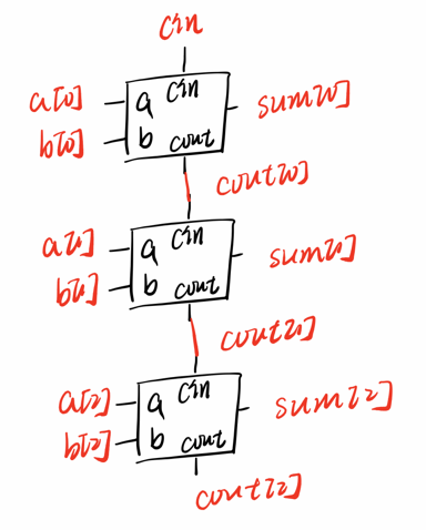
现在您已经知道如何构建一个全加器,创建 3 个实例来创建一个 3 位二进制波纹进位加法器。加法器将两个 3 位数字和一个进位相加以产生一个 3 位和并进位。为了鼓励您实际实例化全加器,还要输出纹波进位加法器中每个全加器的进位。cout[2] 是最后一个全加器的最终进位,也是您通常看到的进位。
module top_module(
    input [2:0] a, b,
    input cin,
    output [2:0] cout,
    output [2:0] sum );

    wire w1,w2;
    add1 U1(a[0],b[0],cin,cout[0],sum[0]);
    add1 U2(a[1],b[1],cout[0],cout[1],sum[1]);
    add1 U3(a[2],b[2],cout[1],cout[2],sum[2]);


endmodule

module add1(
    input a,
    input b,
    input cin,
    output cout,
    output sum);

    assign {cout,sum}=a+b+cin;

endmodule
3.4、Adder
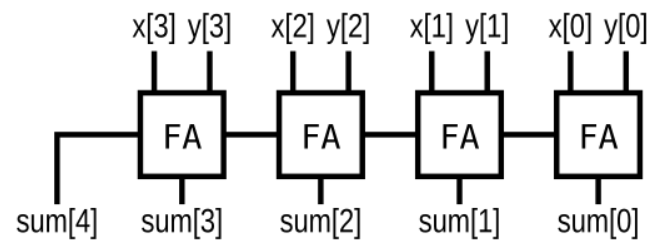
实现以下电路:
(“FA”是一个全加器)
module top_module (
    input [3:0] x,
    input [3:0] y,
    output [4:0] sum);

    wire w1,w2,w3;
    FA U1(.a(x[0]),.b(y[0]),.sum(sum[0]),.cout(w1));
    FA U2(.a(x[1]),.b(y[1]),.cin(w1),.sum(sum[1]),.cout(w2));
    FA U3(.a(x[2]),.b(y[2]),.cin(w2),.sum(sum[2]),.cout(w3));
    FA U4(.a(x[3]),.b(y[3]),.cin(w3),.sum(sum[3]),.cout(sum[4]));
endmodule

module FA(input a,input b,input cin,output sum,output cout);
    assign {cout,sum}=a+b+cin;
endmodule
3.5、Signed addition overflow
假设您有两个 8 位 2 的补码,a[7:0] 和 b[7:0]。这些数字相加产生 s[7:0]。还要计算是否发生了(有符号的)溢出。
1)当两个正数相加产生负结果或两个负数相加产生正结果时,会发生 有符号溢出。
2)有几种检测溢出的方法:它可以通过比较输入和输出数的符号来计算,或者从位 n 和 n-1 的进位推导出来。
module top_module (
    input [7:0] a,
    input [7:0] b,
    output [7:0] s,
    output overflow
); //

    // assign s = ...
    // assign overflow = ...
    assign s=a+b;
    assign overflow=a[7]&b[7]&(~s[7])|(~a[7])&(~b[7])&s[7];
    //assign overflow=a[7]^b[7]~^s[7];错误原因:a为01100_0000,b1100_0000,得s为1_0000_0000,溢出,但是带入公式结果不符合实际

endmodule
3.6、100-bit binary adder
创建一个 100 位二进制加法器。加法器将两个 100 位数字和一个进位相加,产生一个 100 位和并执行。
module top_module(
    input [99:0] a, b,
    input cin,
    output cout,
    output [99:0] sum );

    assign {cout,sum}=a+b+cin;
endmodule
3.7、4-digit BCD adder
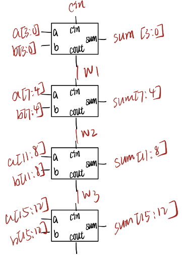
为您提供了一个名为bcd_fadd的 BCD(二进制编码的十进制)一位加法器,它将两个 BCD 数字和进位相加,并产生一个和和进位。
module bcd_fadd (
    input [3:0] a,
    input [3:0] b,
    input     cin,
    output   cout,
    output [3:0] sum );
实例化 4 个bcd_fadd副本以创建一个 4 位 BCD 波纹进位加法器。您的加法器应该将两个 4 位 BCD 数字(打包成 16 位向量)和一个进位相加,以产生一个 4 位和并执行。
module top_module (
    input [15:0] a, b,
    input cin,
    output cout,
    output [15:0] sum );

    wire w1,w2,w3;
    bcd_fadd U1(.a(a[3:0]),.b(b[3:0]),.cin(cin),.sum(sum[3:0]),.cout(w1));
    bcd_fadd U2(.a(a[7:4]),.b(b[7:4]),.cin(w1),.sum(sum[7:4]),.cout(w2));
    bcd_fadd U3(.a(a[11:8]),.b(b[11:8]),.cin(w2),.sum(sum[11:8]),.cout(w3));
    bcd_fadd U4(.a(a[15:12]),.b(b[15:12]),.cin(w3),.sum(sum[15:12]),.cout(cout));
endmodule
四、Karnaugh Map to Circuit
4.1、3-variable
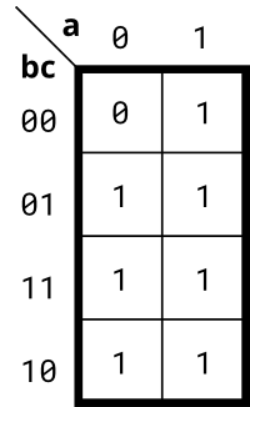
实现下面卡诺图描述的电路。
1)在编码之前尝试简化 k-map。尝试和积和积和形式。
2)我们无法检查您是否有 k-map 的最佳简化。但是我们可以检查你的归约是否等价,我们可以检查你是否可以将 k-map 转换为电路。
module top_module(
    input a,
    input b,
    input c,
    output out  );

   assign out=a|b|c;
endmodule
4.2、4-variable
实现下面卡诺图描述的电路。
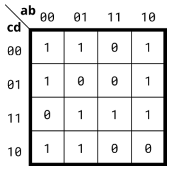
module top_module(
    input a,
    input b,
    input c,
    input d,
    output out  );

    assign out=(~b)&(~c)|(~a)&(~d)|a&c&d|(~a)&b&c;
endmodule
4.3、4-variable
实现下面卡诺图描述的电路。
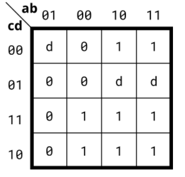
module top_module(
    input a,
    input b,
    input c,
    input d,
    output out  );

    assign out=a|(~b)&c|b&(~c)&(~d);
endmodule
4.4、4-variable
实现下面卡诺图描述的电路。
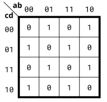
module top_module(
    input a,
    input b,
    input c,
    input d,
    output out  );

    assign out = (~a&~b&~c&d)|(~a&b&~c&~d)|(a&b&~c&d)|(a&~b&~c&~d)|(~a&b&c&d)|(a&~b&c&d)|(~a&~b&c&~d)|(a&b&c&~d);
endmodule
4.5、Minimum SOP and POS
具有四个输入(a、b、c、d)的单输出数字系统在输入上出现 2、7 或 15 时生成逻辑 1,当输入上出现 0、1、4、5、6 、9、10、13 或 14 出现时生成逻辑 0。数字 3、8、11 和 12 的输入条件在此系统中永远不会出现。例如,7 对应于 a、b、c、d 分别设置为 0、1、1、1。
确定最小SOP形式(积之和 最小项)的输出out_sop,以及最小POS形式(和之积 最大项)的输出out_pos。
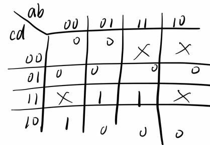
module top_module (
    input a,
    input b,
    input c,
    input d,
    output out_sop,
    output out_pos
);
    assign out_sop=c&d|(~a)&(~b)&c;
    assign out_pos=c&(~a|b)&(~b|d);

endmodule
4.6、Karnaugh map
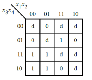
考虑下面卡诺图中所示 的函数f 。
实现这个功能。d是不关心,这意味着您可以选择输出任何方便的值。
module top_module (
    input [4:1] x,
    output f );

    assign f = (~x[1]&x[3])|(x[2]&x[4]);
endmodule
4.7、Karnaugh map
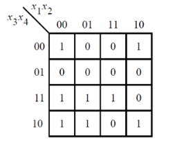
考虑下面卡诺图中所示的函数f 。实现这个功能。
(原始考试问题要求简化 SOP 和 POS 形式的函数。)
module top_module (
    input [4:1] x,
    output f
);

    assign f=(~x[2]&~x[4])|(~x[1]&x[3])|(x[2]&x[3]&x[4]);

endmodule
4.8、K-map implemented with a multiplexer
对于下面的卡诺图,给出使用一个 4 对 1 多路复用器和尽可能多的 2 对 1 多路复用器的电路实现,但使用尽可能少。不允许使用任何其他逻辑门,并且必须使用a和b作为多路复用器选择器输入,如下面的 4 对 1 多路复用器所示。
您只实现了标记为top_module的部分,以便整个电路(包括 4 对 1 多路复用器)实现 K-map。
module top_module (
    input c,
    input d,
    output [3:0] mux_in
);
    assign mux_in[0]=c|d;
    assign mux_in[1]=1'b0;
    assign mux_in[2]=~d;
    assign mux_in[3]=c&d;

endmodule


【推荐】国内首个AI IDE,深度理解中文开发场景,立即下载体验Trae
【推荐】编程新体验,更懂你的AI,立即体验豆包MarsCode编程助手
【推荐】抖音旗下AI助手豆包,你的智能百科全书,全免费不限次数
【推荐】轻量又高性能的 SSH 工具 IShell:AI 加持,快人一步
· 开源Multi-agent AI智能体框架aevatar.ai,欢迎大家贡献代码
· Manus重磅发布:全球首款通用AI代理技术深度解析与实战指南
· 被坑几百块钱后,我竟然真的恢复了删除的微信聊天记录!
· 没有Manus邀请码?试试免邀请码的MGX或者开源的OpenManus吧
· 园子的第一款AI主题卫衣上架——"HELLO! HOW CAN I ASSIST YOU TODAY